2019 MERCEDES-BENZ GLE clock
[x] Cancel search: clockPage 182 of 398
R
Utility vehicles have a significantly higher roll-
over rate than other types of vehicles.
Failure to operate this vehicle safely may
result in an accident, rollover of the vehicle,
and severe or fatal injury.
R In a rollover crash, an unbelted person is sig-
nificantly more likely to die than a person
wearing a seat belt.
You and all vehicle occupants should always
wear your seat belts.
Basic settings The extent to which the vehicle is raised or low-
ered depends on the basic setting selected.
Select:
R the Comfort orSport drive program for driv-
ing on normal roads
R the Offroad drive program for driving on eas-
ily negotiable off-road terrain
R the Offroad Plus drive program for off-road
driving
R offroad level 1 for driving on easily negotiable
off-road terrain
R offroad level 2 for driving on normal off-road
terrain
R offroad level 3 for freeing the vehicle in par-
ticularly rough terrain at low speeds only
The individual vehicle levels differ from the nor- mal level as follows:
R –0.6 in (–15 mm) in the Sportdrive program
R +/–0 in (+/–0 mm) in the Comfortdrive pro-
gram
R + 1.2 in (+ 30 mm) in the Offroaddrive pro-
gram
R + 2.4 in (+ 60 mm) in the Offroad Plusdrive
program
R + 1.2 in (+ 30 mm) in offroad level 1
R + 2.4 in (+ 60 mm) in offroad level 2
R + 3.5 in (+ 90 mm) in offroad level 3
Setting the vehicle level !
Make sure that there is enough ground
clearance when the vehicle is being lowered.
It could otherwise hit the ground, damaging
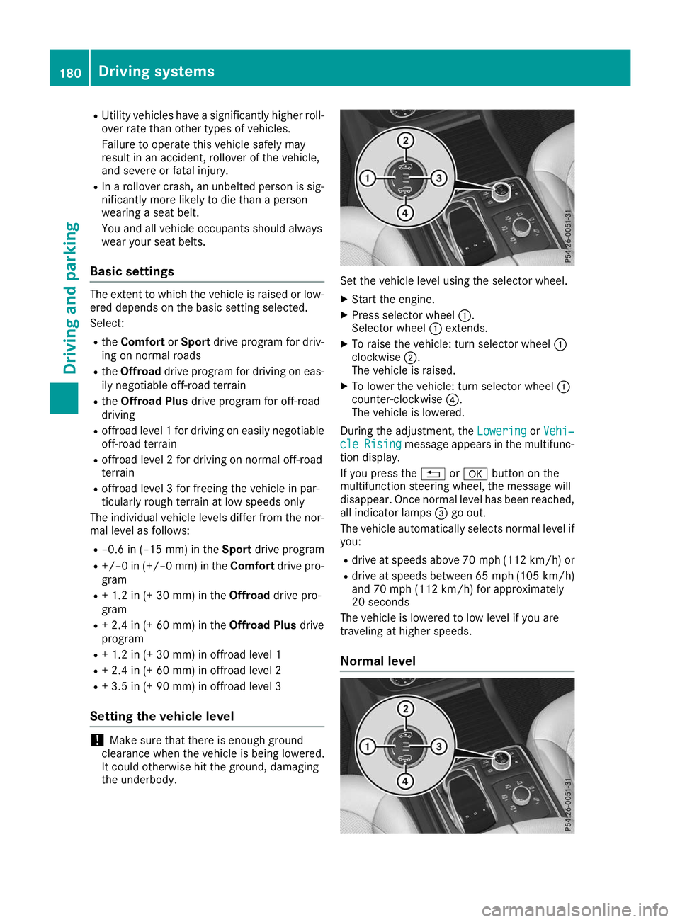
the underbody. Set the vehicle level using the selector wheel.
X Start the engine.
X Press selector wheel 0043.
Selector wheel 0043extends.
X To raise the vehicle: turn selector wheel 0043
clockwise 0044.
The vehicle is raised.
X To lower the vehicle: turn selector wheel 0043
counter-clockwise 0085.
The vehicle is lowered.
During the adjustment, the Lowering LoweringorVehi‐
Vehi‐
cle
cle Rising
Rising message appears in the multifunc-
tion display.
If you press the 0038or0076 button on the
multifunction steering wheel, the message will
disappear. Once normal level has been reached, all indicator lamps 0087go out.
The vehicle automatically selects normal level if
you:
R drive at speeds above 70 mph (112 km/h) or
R drive at speeds between 65 mph (105 km/h)
and 70 mph (112 km/h) for approximately
20 seconds
The vehicle is lowered to low level if you are
traveling at higher speeds.
Normal level 180
Driving systemsDriving and parking
Page 183 of 398
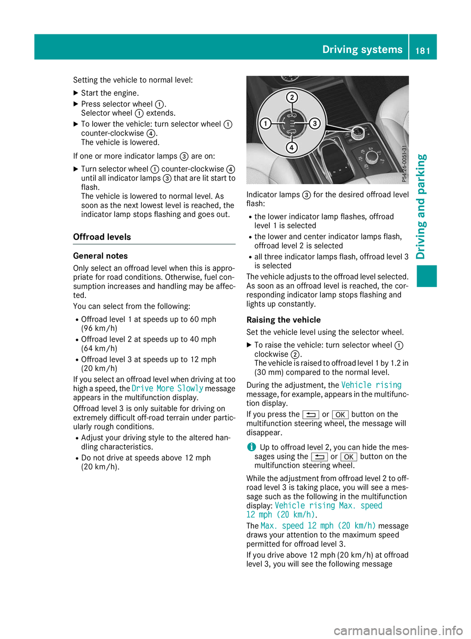
Setting the vehicle to normal level:
X Start the engine.
X Press selector wheel 0043.
Selector wheel 0043extends.
X To lower the vehicle: turn selector wheel 0043
counter-clockwise 0085.
The vehicle is lowered.
If one or more indicator lamps 0087are on:
X Turn selector wheel 0043counter-clockwise 0085
until all indicator lamps 0087that are lit start to
flash.
The vehicle is lowered to normal level. As
soon as the next lowest level is reached, the
indicator lamp stops flashing and goes out.
Offroad levels General notes
Only select an offroad level when this is appro-
priate for road conditions. Otherwise, fuel con-
sumption increases and handling may be affec- ted.
You can select from the following:
R Offroad level 1 at speeds up to 60 mph
(96 km/h)
R Offroad level 2 at speeds up to 40 mph
(64 km/h)
R Offroad level 3 at speeds up to 12 mph
(20 km/h)
If you select an offroad level when driving at too high a speed, the Drive DriveMore
MoreSlowly
Slowly message
appears in the multifunction display.
Offroad level 3 is only suitable for driving on
extremely difficult off-road terrain under partic- ularly rough conditions.
R Adjust your driving style to the altered han-
dling characteristics.
R Do not drive at speeds above 12 mph
(20 km/h). Indicator lamps
0087for the desired offroad level
flash:
R the lower indicator lamp flashes, offroad
level 1 is selected
R the lower and center indicator lamps flash,
offroad level 2 is selected
R all three indicator lamps flash, offroad level 3
is selected
The vehicle adjusts to the offroad level selected.
As soon as an offroad level is reached, the cor-
responding indicator lamp stops flashing and
lights up constantly.
Raising the vehicle
Set the vehicle level using the selector wheel.
X To raise the vehicle: turn selector wheel 0043
clockwise 0044.
The vehicle is raised to offroad level 1 by 1.2 in
(30 mm) compared to the normal level.
During the adjustment, the Vehicle rising
Vehicle rising
message, for example, appears in the multifunc-
tion display.
If you press the 0038or0076 button on the
multifunction steering wheel, the message will
disappear.
i Up to offroad level 2, you can hide the mes-
sages using the 0038or0076 button on the
multifunction steering wheel.
While the adjustment from offroad level 2 to off-
road level 3 is taking place, you will see a mes-
sage such as the following in the multifunction
display: Vehicle rising Max. speed Vehicle rising Max. speed
12 mph (20 km/h)
12 mph (20 km/h).
The Max. Max. speed
speed 12 mph
12 mph (20 km/h)
(20 km/h) message
draws your attention to the maximum speed
permitted for offroad level 3.
If you drive above 12 mph (20 km/h) at offroad
level 3, you will see the following message Driving systems
181Driving and parking Z
Page 231 of 398
Important safety notes
G
WARNING
If you operate information systems and com-
munication equipment integrated in the vehi- cle when driving, you may be distracted from
the traffic situation. You could also lose con-
trol of the vehicle. There is a risk of an acci-
dent.
Only operate this equipment when the traffic
situation permits. If you are not sure that this
is possible, park the vehicle paying attention
to traffic conditions and operate the equip-
ment when the vehicle is stationary.
You must observe the legal requirements for the country in which you are currently driving whenoperating the on-board computer. G
WARNING
If the instrument cluster has failed or mal-
functioned, you may not recognize function
restrictions in systems relevant to safety. The operating safety of your vehicle may be
impaired. There is a risk of an accident.
Pull over as soon as it is safe to do so and
consult a qualified specialist workshop.
The on-board computer only shows messages or
warnings from certain systems in the multifunc- tion display. You should therefore make sure
your vehicle is operating safely at all times.
For an overview, see the instrument panel illus-
tration (Y page 37).
Plug-in hybrid: be sure to read the separate
Operator's Manual. Otherwise, you may not rec-
ognize dangers. Displays and operation
Instrument cluster lighting
The lighting in the instrument cluster, in the dis- plays and the controls in the vehicle interior can
be adjusted using the brightness control knob.
The brightness control knob is located on the
bottom left of the instrument cluster
(Y page 37). X
Turn the brightness control knob clockwise or
counter-clockwise.
If you turn the light switch to 0058,0060or
0058, the brightness is dependent upon the
brightness of the ambient light.
i The light sensor in the instrument cluster
automatically controls the brightness of the
multifunction display.
In daylight, the displays in the instrument
cluster are not illuminated. Speedometer with segments
The segments in the speedometer indicate
which speed range is available.
R Cruise control activated (Y page 169):
The segments light up from the stored speed to the maximum speed.
R Active Distance Assist DISTRONIC activated
(Y page 171):
One or two segments in the set speed range
light up.
R Active Distance Assist DISTRONIC detects a
vehicle in front moving more slowly than the
stored speed:
The segments between the speed of the vehi- cle in front and the stored speed light up. Tachometer
! Do not drive in the overrevving range, as this
could damage the engine.
The red band in the tachometer indicates the
engine's overrevving range.
The fuel supply is interrupted to protect the
engine when the red band is reached. Outside temperature display
You should pay special attention to road condi-
tions when temperatures are around freezing
point.
Bear in mind that the outside temperature dis-
play indicates the temperature measured and
does not record the road temperature.
The outside temperature display is in the multi-
function display (Y page 231). Displays and operation
229On-board computer and displays Z
Page 325 of 398
When checking the oil level:
R
park the vehicle on a level surface.
R the engine should be switched off for approx-
imately five minutes if the engine is at normal
operating temperature.
R if the engine is not at normal operating tem-
perature, e.g. if the engine was only started
briefly, wait about 30 minutes before carrying
out the measurement.
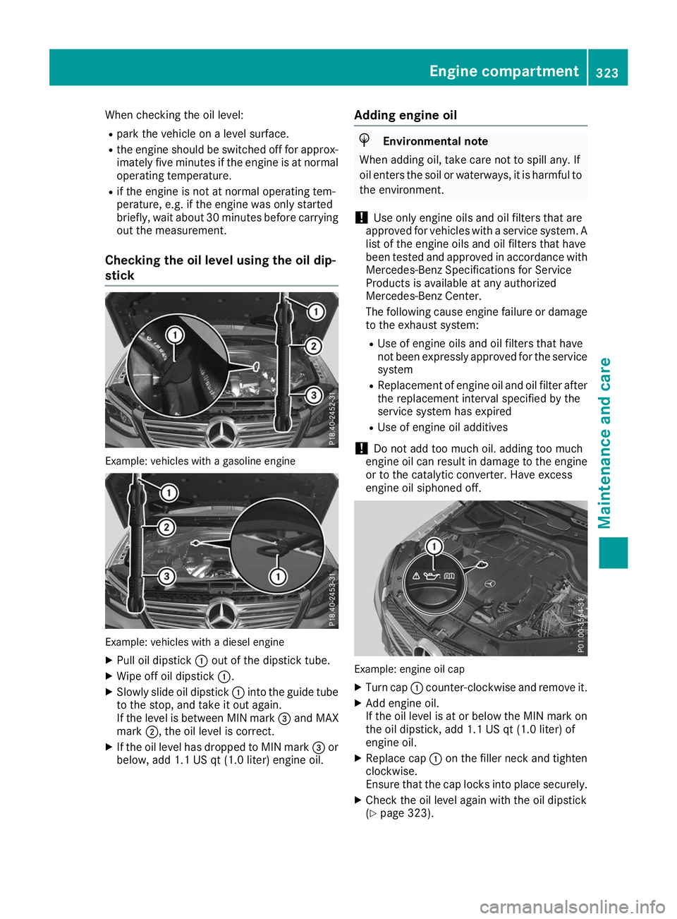
Checking the oil level using the oil dip-
stick Example: vehicles with a gasoline engine
Example: vehicles with a diesel engine
X Pull oil dipstick 0043out of the dipstick tube.
X Wipe off oil dipstick 0043.
X Slowly slide oil dipstick 0043into the guide tube
to the stop, and take it out again.
If the level is between MIN mark 0087and MAX
mark 0044, the oil level is correct.
X If the oil level has dropped to MIN mark 0087or
below, add 1.1 US qt (1.0 liter) engine oil. Adding engine oil H
Environmental note
When adding oil, take care not to spill any. If
oil enters the soil or waterways, it is harmful to the environment.
! Use only engine oils and oil filters that are
approved for vehicles with a service system. A list of the engine oils and oil filters that have
been tested and approved in accordance with
Mercedes-Benz Specifications for Service
Products is available at any authorized
Mercedes-Benz Center.
The following cause engine failure or damage
to the exhaust system:
R Use of engine oils and oil filters that have
not been expressly approved for the service
system
R Replacement of engine oil and oil filter after
the replacement interval specified by the
service system has expired
R Use of engine oil additives
! Do not add too much oil. adding too much
engine oil can result in damage to the engine or to the catalytic converter. Have excess
engine oil siphoned off. Example: engine oil cap
X Turn cap 0043counter-clockwise and remove it.
X Add engine oil.
If the oil level is at or below the MIN mark on
the oil dipstick, add 1.1 US qt (1.0 liter) of
engine oil.
X Replace cap 0043on the filler neck and tighten
clockwise.
Ensure that the cap locks into place securely.
X Check the oil level again with the oil dipstick
(Y page 323). Engine compartment
323Maintenance and care Z
Page 326 of 398
Further information on engine oil (Y
page 387).Additional service products
Important safety notes G
WARNING
Certain components in the engine compart-
ment, such as the engine, radiator and parts
of the exhaust system, can become very hot.
Working in the engine compartment poses a
risk of injury.
Where possible, let the engine cool down and touch only the components described in the
following. G
WARNING
The cooling system is pressurized, particularly when the motor is warm. If you open the cap, you could be scalded if hot coolant sprays out.
There is a risk of injury.
Let the engine cool down before you open the
cap. Wear protective gloves and protective
eyewear when opening. Open the cap slowly
to release pressure.
The coolant level may only be checked and cool- ant refilled when the engine and engine coolingsystem have cooled down. G
WARNING
Windshield washer concentrate could ignite if it comes into contact with hot engine compo-
nents or the exhaust system. There is a risk of
fire and injury.
Make sure that no windshield washer con-
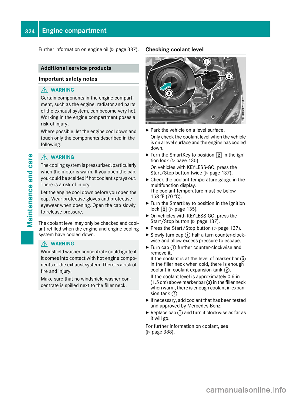
centrate is spilled next to the filler neck. Checking coolant level X
Park the vehicle on a level surface.
Only check the coolant level when the vehicle
is on a level surface and the engine has cooled
down.
X Turn the SmartKey to position 0048in the igni-
tion lock (Y page 135).
On vehicles with KEYLESS-GO, press the
Start/Stop button twice (Y page 137).
X Check the coolant temperature gauge in the
multifunction display.
The coolant temperature must be below
158 ‡ (70 †).
X Turn the SmartKey to position in the ignition
lock 0092(Ypage 135).
X On vehicles with KEYLESS-GO, press the
Start/Stop button (Y page 137).
X Press the Start/Stop button (Y page 137).
X Slowly turn cap 0043half a turn counter-clock-
wise and allow excess pressure to escape.
X Turn cap 0043further counter-clockwise and
remove it.
If the coolant is at the level of marker bar 0087
in the filler neck when cold, there is enough
coolant in coolant expansion tank 0044.
If the coolant level is approximately 0.6 in
(1.5 cm) above marker bar 0087in the filler neck
when warm, there is enough coolant in expan- sion tank 0044.
X If necessary, add coolant that has been tested
and approved by Mercedes-Benz.
X Replace cap 0043and turn it clockwise as far as
it will go.
For further information on coolant, see
(Y page 388). 324
Engine compartmentMaintenance and care
Page 344 of 398
occupants from suffering acid burns should the
battery be damaged in the event of an accident.
In order for the battery to achieve the maximum possible service life, it must always be suffi-
ciently charged.
Like other batteries, the vehicle battery may
discharge over time if you do not use the vehicle. In this case, have the battery disconnected at a
qualified specialist workshop. However, you can also charge the battery with a charger recom-
mended by Mercedes-Benz. Contact a qualified
specialist workshop for further information.
Have the battery charge state checked more
frequently if you use the vehicle mainly for short trips or if you leave it standing idle for a lengthyperiod. Consult a qualified specialist workshop
if you wish to leave your vehicle parked for a long
period of time.
Remove the SmartKey if you park the vehicle
and do not require any electrical consumers.
The vehicle will then use very little energy, thus
conserving battery power.
If the power supply has been interrupted, e.g. if
you reconnect the battery, you will have to:
R set the clock (see the Digital Operator's Man-
ual)
On vehicles with a multimedia system and
navigation system, the clock is set automati-
cally.
R reset the function for automatically folding
the exterior mirrors in/out by folding the mir-
rors out once(Y page 106) Charging the 12 V battery
G
WARNING
During charging and jump-starting, explosive
gases can escape from the battery. There is a risk of an explosion.
Particularly avoid fire, open flames, creating
sparks and smoking. Ensure there is sufficient
ventilation while charging and jump-starting.
Do not lean over a battery. G
WARNING
Battery acid is caustic. There is a risk of injury. Avoid contact with skin, eyes or clothing. Do
not inhale any battery gases. Do not lean over
the battery. Keep children away from batter- ies. Wash away battery acid immediately with
plenty of clean water and seek medical atten-tion. G
WARNING
A discharged battery can freeze at tempera-
tures below freezing point. When jump-start-
ing the vehicle or charging the battery, gases can escape from the battery. There is a risk of
an explosion.
Allow the frozen battery to thaw out before
charging it or jump-starting.
! Only use battery chargers with a maximum
charging voltage of 14.8 V.
! Only charge the battery using the jump-
starting connection point.
The jump-starting connection point is in the
engine compartment (Y page 343).
X Open the hood.
X Connect the battery charger to the positive
terminal and ground point in the same order
as when connecting the donor battery in the
jump-starting procedure (Y page 343).
Keep away from fire and open flames. Do not
lean over a battery. Never charge the battery if it is still installed in the vehicle, unless you use a
battery charger which has been tested and
approved by Mercedes-Benz. A battery charger
unit specially adapted for Mercedes-Benz vehi-
cles and tested and approved by Mercedes-
Benz is available as an accessory. It permits the
charging of the battery in its installed position.
Contact an authorized Mercedes-Benz Center
for further information and availability. Read the battery charger's operating instructions before
charging the battery.
If, at low temperatures, the indicator lamps/
warning lamps in the instrument cluster do not
light up, it is highly likely that the discharged
battery has frozen. In this case you may neither
jump-start the vehicle nor charge the battery.
The service life of a thawed-out battery may be
shorter. The starting characteristics can be
impaired, particularly at low temperatures. Have
the thawed-out battery checked at a qualified
specialist workshop. 342
Battery (vehicle)Breakdown assistance
Page 349 of 398
The battery must be connected and charged.
Otherwise, you:
R cannot turn the SmartKey to position 0048in
the ignition lock
R cannot release the electric parking brake.
R cannot shift the automatic transmission to
position 005C
Disarm the automatic locking feature before the vehicle is towed (Y page 240). You could other-
wise be locked out when pushing or towing the
vehicle.
If the vehicle is in a dangerous area, it can be
towed out of that area with both axles on the
ground. In this case, the towing distance must
not be greater than 165 ft (50 m)and must not
exceed a towing speed of 6 mph (10 km/h). For
longer distances, have the vehicle loaded and
transported. Permitted towing methods
Mercedes-Benz recommends transporting your
vehicle in the case of a breakdown, rather than
towing it away.
When towing away, use a towing rope or a tow-
ing bar with both axles on the ground. Do not use any tow bar systems. Installing/removing the towing eye
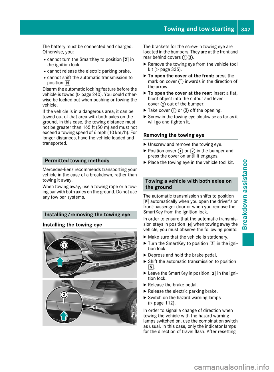
Installing the towing eye The brackets for the screw-in towing eye are
located in the bumpers. They are at the front and
rear behind covers 00430044.
X Remove the towing eye from the vehicle tool
kit (Y page 335).
X To open the cover at the front: press the
mark on cover 0043inwards in the direction of
the arrow.
X To open the cover at the rear: insert a flat,
blunt object into the cutout and lever
cover 0044out of the bumper.
X Take cover 0043or0044 off the opening.
X Screw in the towing eye clockwise as far as it
will go and tighten it.
Removing the towing eye X
Unscrew and remove the towing eye.
X Position cover 0043or0044 in the bumper and
press the cover on until it engages.
X Place the towing eye in the vehicle tool kit. Towing a vehicle with both axles on
the ground
The automatic transmission shifts to position
005D automatically when you open the driver's or
front-passenger door or when you remove the
SmartKey from the ignition lock.
In order to ensure that the automatic transmis-
sion stays in position 005Cwhen towing away the
vehicle, you must observe the following points:
X Make sure that the vehicle is stationary.
X Turn the SmartKey to position 0048in the igni-
tion lock.
X Depress and hold the brake pedal.
X Shift the automatic transmission to position
005C.
X Leave the SmartKey in position 0048in the igni-
tion lock.
X Release the brake pedal.
X Release the electric parking brake.
X Switch on the hazard warning lamps
(Y page 112).
In order to signal a change of direction when
towing the vehicle with the hazard warning
lamps switched on, use the combination switch
as usual. In this case, only the indicator lamps
for the direction of travel flash. After resetting Towing and tow-starting
347Breakdown assistance Z
Page 379 of 398
R
only use a spare wheel or emergency spare
wheel of a different size briefly.
R do not switch ESP ®
off.
R have a spare wheel or emergency spare
wheel of a different size replaced at the
nearest qualified specialist workshop.
Observe that the wheel and tire dimensions
as well as the tire type must be correct.
! Mercedes-AMG vehicles with
"Minispare" emergency spare wheel: only
use the "Minispare" emergency spare wheel
on the rear axle. If you mount the
"Minispare" emergency spare wheel on the
front axle, this could result in damage to the
brake system.
If a tire on the front axle is defective, an intact
wheel from the rear axle must first be
replaced with the "Minispare" emergency
spare wheel. The damaged wheel on the front
axle can then be replaced by the undamaged wheel from the rear axle.
Make sure to note the placard on the
"Minispare" emergency spare wheel.
When using an emergency spare wheel or spare wheel of a different size, you must not exceed
the maximum speed of 50 mph (80 km/h).
You should regularly check the pressure of the
emergency spare wheel, particularly prior to
long trips, and correct the pressure as neces-
sary (Y page 354). The value on the wheel is
valid.
Snow chains must not be mounted on emer-
gency spare wheels. General notes
Information regarding permitted emergency
spare wheels can be found at an authorized
Mercedes-Benz Center.
Mounting the emergency spare wheel is descri- bed under "Mounting a wheel" (Y page 372).
An emergency spare wheel may also be moun-
ted against the direction of rotation. Observe
the time restriction on use as well as the speed
limitation specified on the emergency spare
wheel.
Replace the tires after six years at the latest,
regardless of wear. This also applies to the
emergency spare wheel. When you are driving with the collapsible spare
wheel mounted, the tire pressure loss warning
system or the tire pressure monitor cannot func-
tion reliably. Only restart the tire pressure loss
warning system or tire pressure monitor when
the defective wheel has been replaced with a
new wheel.
Vehicles with tire pressure monitor: after
mounting an emergency spare wheel, the sys-
tem may still display the tire pressure of the
removed wheel for a few minutes. The value dis- played for the mounted emergency spare wheelis not the same as the current tire pressure of
the emergency spare wheel. Removing/stowing the emergency
spare wheel
Vehicles with a "Minispare" emergency
spare wheel under the cargo compart-
ment floor Always observe the instructions and safety
notes in the "Mounting a wheel" section
(Y
page 372).
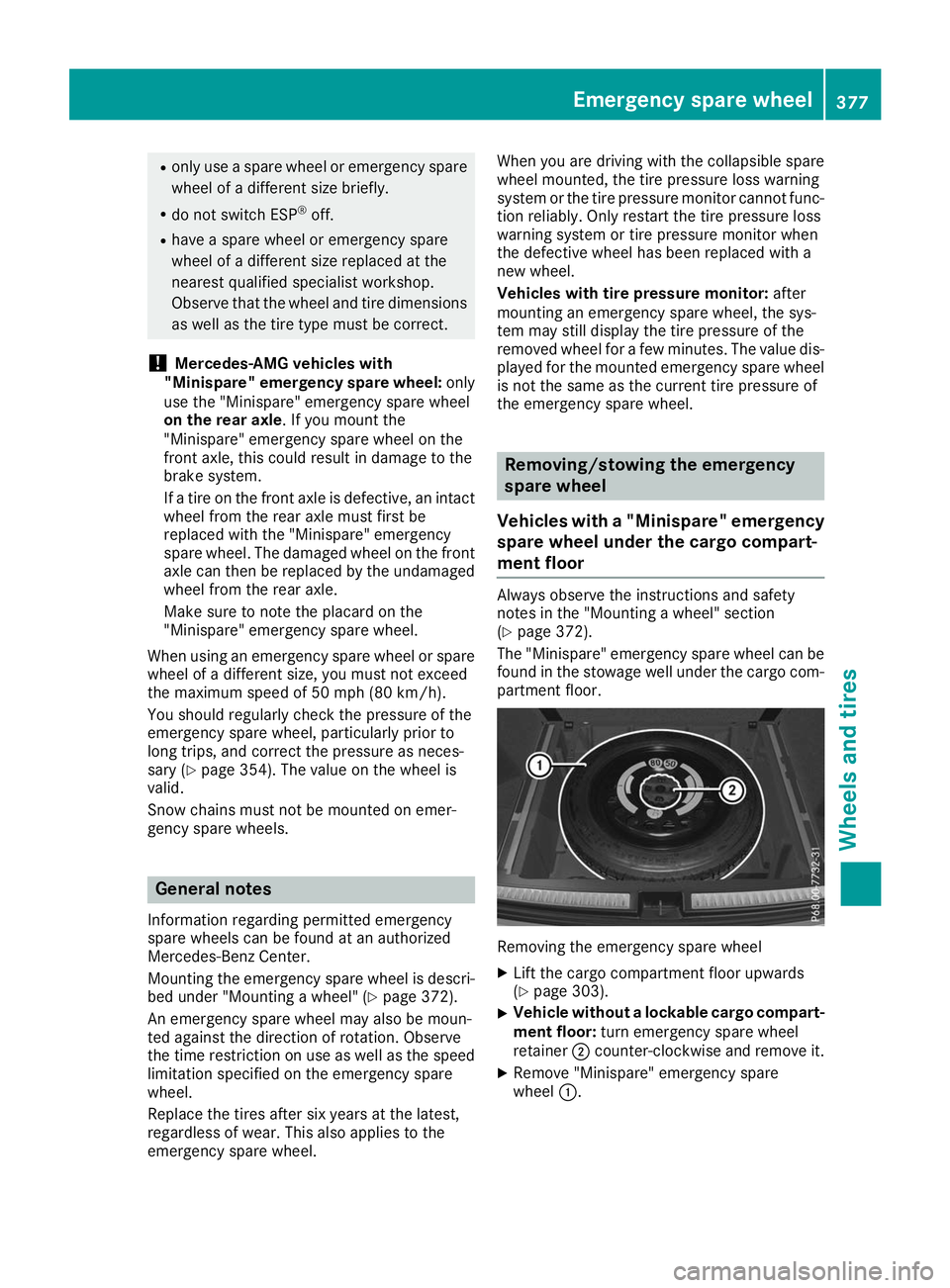
The "Minispare" emergency spare wheel can be found in the stowage well under the cargo com-
partment floor. Removing the emergency spare wheel
X Lift the cargo compartment floor upwards
(Y page 303).
X Vehicle without a lockable cargo compart-
ment floor: turn emergency spare wheel
retainer 0044counter-clockwise and remove it.
X Remove "Minispare" emergency spare
wheel 0043. Emergency spare wheel
377Wheels and tires Z