2019 MERCEDES-BENZ GLE COUPE parking brake
[x] Cancel search: parking brakePage 216 of 697
Count
ryRadio equipment appr oval
number
Mexico RCPGEMU15-0448
Monaco CE
New Zea‐
land R-
NZ
Nor wayCE
Ru ssian
Fe dera‐
tion Not
requ ired
Saudi Ara‐
bia TA
10525
Switzer‐
land CE
South
Africa TA
-20 15/1386 Countr
yRadio equipment appr oval
number
Tu rkey Notrequ ired
Uni ted
Arab Emi‐
ra tes ER4
1849/15
Dealer No: DA35176/14
United
St ates FCC ID: NZLM
UAHL5 Fu
rther information on the declaration of con‐
fo rm ity for wireless vehicle components
(/ page 26). Electric parking brake
Electric parking brake function (applying
automatically) &
WARNING Risk of accident and inju ry
due tochildren left unat tended in the
ve hicle
If ch ildren are left unat tended in theve hicle,
th ey could:
R Open doo rs,th ereby endangering other
persons or road users.
R Get out and be stru ck byoncoming traf‐
fi c.
R Ope rate ve hicle equipment and become
trapped, forex ample.
In addition, thech ildren could also set the
ve hicle in motion, forex ample by:
R Releasing the parking brake.
R Changing the transmission position.
R Starting theve hicle. Driving and parking
213
Page 217 of 697
#
Never lea vechildren unat tended in the
ve hicle. #
When leaving theve hicle, alw aysta ke
th eke y with you and lock theve hicle. #
Keep theve hicle key out of reach of
ch ildren. This also applies
tothe Digital Vehicle Key if the
"Digital Vehicle Key" function is activated via
Mercedes me connect.
The electric parking brake is applied if the trans‐
mission is in position jand one of thefo llow‐
ing conditions is fulfilled:
R The engine is switched off.
R The seat belt tongue is not inser ted in the
seat belt buckle of the driver's seat and the
driver's door is opened.
% Toprev ent application: pull the handle of the
electric parking brake.
In thefo llowing situations, the electric parking
brake is also applied:
R Active Dis tance Assi stDISTRONIC is bringing
th eve hicle toast andstill. R
The HOLD function is keeping theve hicle sta‐
tionar y.
R Active Parking Assist is keeping theve hicle
st ationar y.
This is the case if one of thefo llowing conditions
is also fulfilled:
R The engine is switched off.
R The seat belt tongue is not inser ted in the
seat belt buckle of the driver's seat and the
driver's door is opened.
R There is a sy stem malfunction.
R The po wer supply is insuf ficient.
R The vehicle is stationary for a lengt hyperiod.
When the electric parking brake is applied, the
re d! indicator lamp appears in the instru‐
ment clus ter.
The electric parking brake is not automatically
applied if the engine is switched off bythe ECO
st art/ stop function. Electric parking brake function (releasing
automatically)
The electric parking brake is released when the
fo llowing conditions are fulfilled:
R The driver's door is closed.
R The engine is running.
R The transmission is in position hork and
yo u depress the accelera tor pedal or you
shift from transmission position jtoh or
k when on le velground withthe driver's
door closed.
R Ifth e transmission is in position k,theta il‐
gate must be closed.
R The seat belt tongue is inser ted into the seat
belt buckle of the driver's seat.
If th e seat belt tongue is not inser ted into the
seat belt buckle of the driver's seat, thefo llow‐
ing conditions must be fulfilled:
R You shift from transmission position j.
R You ha veprev iously driven at speeds greater
th an 3 km/h 214
Driving and pa rking
Page 218 of 697
When
the electric parking brake is released, the
re d! indicator lamp in the instrument clus‐
te r goes out.
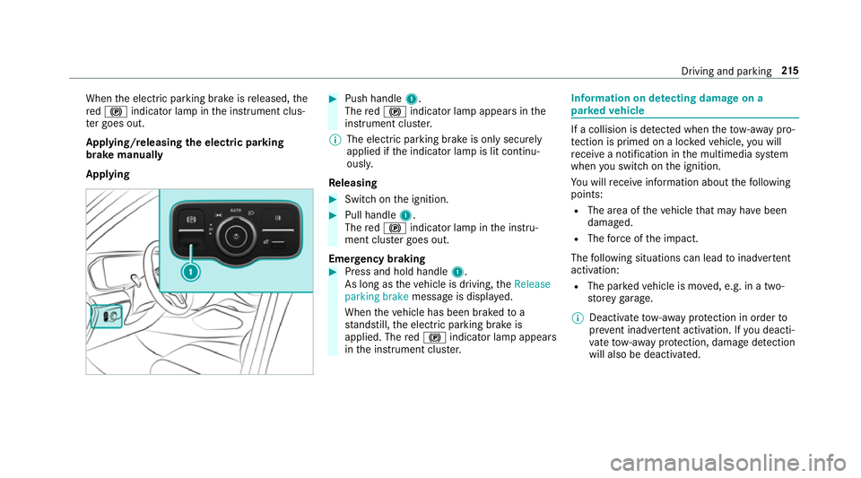
Applying/releasing the electric pa rking
brake manually
Applying #
Push handle 1.
The red! indicator lamp appears in the
instrument clus ter.
% The electric parking brake is only securely
applied if the indicator lamp is lit continu‐
ously.
Re leasing #
Swit chon the ignition. #
Pull handle 1.
The red! indicator lamp in the instru‐
ment clus ter goes out.
Emer gency braking #
Press and hold handle 1.
As long as theve hicle is driving, theRelease
parking brake message is displa yed.
When theve hicle has been braked to a
st andstill, the electric parking brake is
applied. The red! indicator lamp appears
in the instrument clus ter. Information on de
tecting dama geon a
pa rked vehicle If a collision is de
tected when theto w- aw ay pro‐
te ction is primed on a loc kedve hicle, you will
re cei vea notification in the multimedia sy stem
when you swit chon the ignition.
Yo u will recei veinformation about thefo llowing
points:
R The area of theve hicle that may ha vebeen
damaged.
R The forc e of the impact.
The following situations can lead toinadver tent
acti vation:
R The pa rked vehicle is mo ved, e.g. in a two-
st or ey garage.
% Deactivate tow- aw ay protection in order to
pr eve nt inadver tent acti vation. If you deacti‐
va te tow- aw ay protection, damage de tection
will also be deactivated. Driving and pa
rking 215
Page 219 of 697
Sy
stem limits
De tection may be restricted in thefo llowing sit‐
uations:
R The vehicle is damaged without impact, e.g.
if an outside mir ror is torn off or the paint is
damaged byakey.
R Impact occurs at low speed.
R The electric parking brake is not applied. Note
s on parking up theve hicle If
yo u lea vetheve hicle par ked up for longer than
six weeks, it may suf fer disuse dama ge.
The 12V battery may also be impaired or dam‐
aged byheavy discharging.
% Further information can be obtained at a
qu alified specialist workshop. St
andby mode (extension of the star ter bat‐
te ry 's period out of use) St
andby mode function
% This function is not available for all models. If
standby mode is activated, ene rgy loss will be
minimised during extended pe riods of non-oper‐
ation.
St andby mode is characterised bythefo llowing:
R thest ar ter battery is preser ved.
R the maximum non-operational time appears
in the media displa y.
R the connection toonline services is inter rup‐
te d.
R theAT A (anti-theft alarm sy stem) is not avail‐
able.
R the interior pr otection and tow- aw ay protec‐
tion functions are not available.
R the function for de tecting damage on a
pa rked vehicle is not available.
If th efo llowing conditions are fulfilled, standby
mode can be activated or deactivated using the
multimedia sy stem:
R the engine is switched off.
R the ignition is switched on.
Exceeding theve hicle's displa yed non-opera‐
tional time may cause incon venience, i.e. it can‐ not be guaranteed
that thest ar ter battery will
re liably start the engine.
The star ter battery must be charge dfirs t in the
fo llowing situations:
R The vehicle's non-operational time must be
ex tended.
R The Battery charge insufficient for standby
mode messa geappears in the media displa y.
% Standby mode is automatically deactivated
when the ignition is switched on.
Ac tivating/deactivating standby mode (park‐
ing up theve hicle)
Re quirements:
R The engine is switched off.
Multimedia sy stem:
4 © 5
Settings 5
Vehicle #
Switch Standby mode on or off.
When you activate the function, a prom pt
appears. #
Select Yes.
St andby mode is activated. 216
Driving and pa rking
Page 220 of 697
Driving and driving saf
ety sy stems Driving sy
stems and your responsibility Yo
ur vehicle is equipped with driving sy stems
which assist you in driving, parking and manoeu‐
vring theve hicle. The driving sy stems are aids
and do not relie ve you of your responsibility per‐
ta ining toroad traf fic la w.Pay attention tothe
traf fic conditions at all times and inter vene
when necessa ry. Be aware of the limitations
re ga rding the safe use of these sy stems. Information on
radar and ultrasonic senso rsSome driving and driving sa
fety sy stems use
ra dar or ultrasonic sensors tomonitor the area
in front of, behind or next totheve hicle (depend‐
ing on theve hicle's equipment).
Depending on theve hicle's equipment, thera dar
sensors are integrated behind the bumpers
and/or behind the Mercedes star. The ultrasonic
sensors are located in the front and rear bump‐
ers. Keep these parts free of dirt, ice and slush
(/ page 509). The sensors must not be cov‐
ered, forex ample bybicycle rack s, ove rhanging loads,
sticke rs,fo il or foils toprotect against
st one chipping. Additional license plate brac kets
can li kewise impair the function of the ultrasonic
sensors. In theev ent of damage tothe bumpers
or radiator grille, or following a collision impact‐
ing the bumpers or radiator grille, ha vethe func‐
tion of the sensors checked at a qualified spe‐
cialist workshop. If the sensors are damaged,
some driving sy stems and driving saf ety sy stems
may no longer function proper ly. Overview of driving sy
stems and driving
saf ety sy stems In
this section, you will find information about
th efo llowing driving sy stems and driving saf ety
sy stems:
R 360° Camera (/ page275)
R ABS (A nti-lock Braking System)
(/ page 218)
R Active Dis tance Assi stDISTRONIC
(/ page 236)
R Adaptive Brake Lights (/ page 230)
R AIRMATIC (/ page 251) R
Active Brake Assi st (/ page 224)
R Active Lane Keeping Assist (/ page 294)
R Start-off assist (/ page 251)
R ATTENTION ASSIST (/ page 285)
R BAS (Bra keAssist System) (/ page218)
R Hill Start Assist (/ page249)
R DSR (Dow nhillSpeed Regulation)
(/ page 234)
R E-AC TIVE BODY CONTROL (/ page 255)
R EBD ( Electronic Brakeforc eDistribution)
(/ page 224)
R ESP ®
(Elect ronic Stability Program)
(/ page 219)
R Off- road ESP ®
(/ page 222)
R ESP ®
Crosswind Assist (/ page 223)
R ESP ®
trailer stabilisation (/ page 223)
R Speed Limit Assist (/ page 286)
R Active Speed Limit Assi st (/ page 240)
R HOLD function (/ page249)
R STEER CONTROL (/ page 224) Driving and parking
217
Page 221 of 697
R
Active Steering Assist with rescue lane func‐
tion (/ page243)
R Limi ter (/ page 231)
R Active Emergency Stop Assist (/ page246)
R Active Parking Assist (/ page279)
R Parking Assist PARKTRONIC (/ page 264)
R Reversing camera (/ page271)
R Active Lane Change Assi st (/ page 245)
R Active Traf fic Jam Assi st (/ page 247)
R Cruise control (/ page 230)
R Blind Spot Assist and Active Blind Spot Assi st
with exitwa rning (/ page 290)
R Traf fic Sign Assi st (/ page 288) Fu
nction of ABS The Anti-lock Brake Sy
stem (ABS) regulates the
brake pressure in critical driving situations:
R During braking, e.g. at full brake application
or insuf ficient tyre traction, the wheels are
pr eve nted from lo cking.
R Vehicle steerability while braking is ensured. If ABS inter
venes when braking, you will feel a
pulsing in the brake pedal. The pulsating brake
pedal can be an indication of hazardous road
conditions and can ser veas a reminder totake
ex tra care while driving.
Sy stem limits
R ABS is active from speeds of appr ox.
8 km/h.
R ABS may be impai red or may not function if a
malfunction has occur red and theye l‐
low ! ABSwarning lamp lights up contin‐
uously in the instrument clus ter af terthe
engine is star ted. Fu
nctions of Off-road ABS %
Off-road ABS is activated automatically when
you select theF drive program.
Off-road ABS is specially adap tedfo r driving off-
ro ad:
R The front wheels lock cyclically during brak‐
ing.
R The braking dis tance is sho rtened due tothe
digging-in ef fect. Sy
stem limits
R Off- road ABS functions at speeds below
40 km/h.
R If Off- road ABS inter venes, the ability tosteer
may be restricted. Fu
nction of BAS (Brake Assist Sy stem) &
WARNING Risk of an accident caused by
a malfunction in BAS (Brake Assi stSys‐
te m)
If BA S is malfunctioning, the braking dis tance
in an eme rgency braking situation is
increased. #
Depress the brake pedal with full force
in emer gency braking situations. ABS
pr eve nts the wheels from locking. BA
S suppo rts yo ur eme rgency braking situation
with additional brake forc e. 218
Driving and pa rking
Page 223 of 697
If
th e÷ ESP®
wa rning lamp flashes in the
instrument clus ter,one or se veralve hicle wheels
has reached its grip limit:
R Adapt your driving style to suit the cur rent
ro ad and weather conditions.
R Do not deactivate ESP ®
.
R Onlydepress the accelera tor pedal as far as
is necessary when pulling away.
It can be advantageous todeactivate ESP ®
in the
fo llowing situations toimpr ovetraction:
R When using snow chains.
R In deep sn ow.
R On sand or gr avel. %
Spinning the wheels results in a cutting
action, which enhances traction.
If th e÷ ESP®
wa rning lamp lights up continu‐
ousl y,ESP ®
is not available due toa malfunction.
Obse rveth efo llowing information:
R Warning and indicator lamps (/ page 633)
R Display messages (/ page577)
ETS/4ETS (Elect ronic Traction Sy stem)
ETS/4E TStraction control is pa rtof ESP ®
and
makes it possible topull away and accelerate on
a slippe rycar riag ew ay.
If yo u select theF drive prog ram, a special
ETS sy stem specifically suited tooff-road terrain
is automatically activated. ETS/4E
TScan impr ovetheve hicle's traction by
inter vening in thefo llowing ways:
R The drive wheels are braked individually if
they spin.
R More drive torque is transferred tothe wheel
or wheels with traction.
Influence of drive prog rams on ESP ®
The drive prog rams enable ESP ®
to adapt todif‐
fe re nt we ather and road conditions as well as
th e driver's prefer red driving style. You can
select the drive prog rams using theDY NA MIC
SELECT switch (/ page195). 220
Driving and parking
Page 226 of 697
ESP
®
is deacti vated if theå ESP®
OFF warn‐
ing lamp lights up continuously in the instrument
clus ter.
Obser vethe information on warning lamps and
display messages which may be shown in the
instrument clus ter. Ac
tivating/deactivating ESP ®
(vehicles with
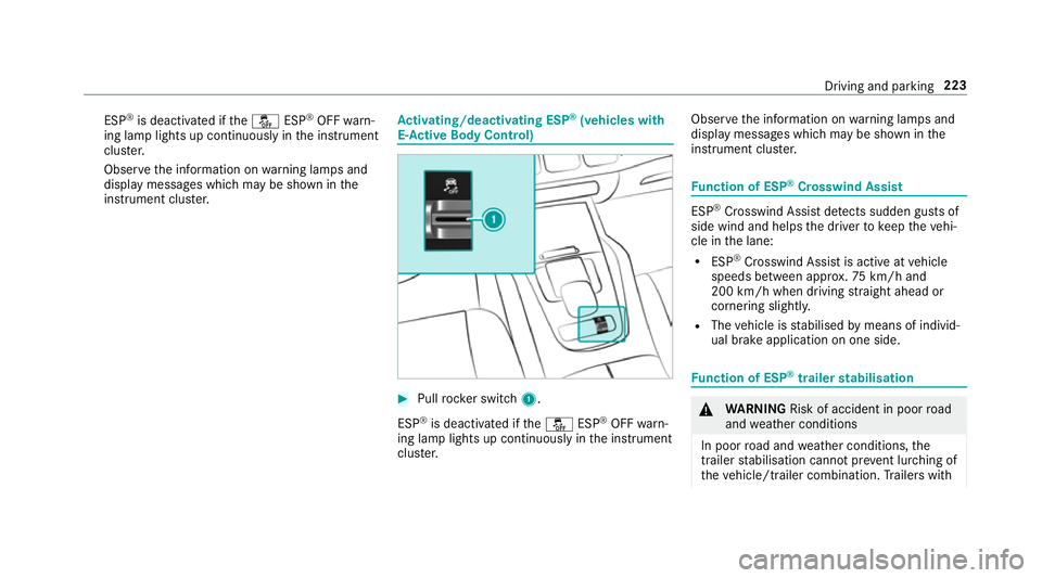
E- Ac tive Body Control) #
Pull rock er switch 1.
ESP ®
is deactivated if theå ESP®
OFF warn‐
ing lamp lights up continuously in the instrument
clus ter. Obser
vethe information on warning lamps and
display messages which may be shown in the
instrument clus ter. Fu
nction of ESP ®
Crosswind Assist ESP
®
Crosswind Assist de tects sudden gu sts of
side wind and helps the driver tokeep theve hi‐
cle in the lane:
R ESP ®
Crosswind Assist is active at vehicle
speeds between appr ox.75 km/h and
200 km/h when driving stra ight ahead or
cornering slightly.
R The vehicle is stabilised bymeans of individ‐
ual brake application on one side. Fu
nction of ESP ®
trailer stabilisation &
WARNING Risk of accident in poor road
and weather conditions
In poor road and weather conditions, the
trailer stabilisation cannot pr event lu rching of
th eve hicle/trailer combination. Trailers with Driving and parking
223