2019 MERCEDES-BENZ GLC SUV trailer
[x] Cancel search: trailerPage 285 of 673
te
ms, safe driving characteristics cannot be
guaranteed forth eto wing vehicle or theto wed
ve hicle. The vehicle-trailer combination may
swer vefrom side toside. Comply with the per‐
mitted towing me thods (/ page 507) and the
instructions forto wing with bo thaxles on the
ground ( /page 508). 282
Driving and parking
Page 381 of 673
#
Tocall the destination: if atelephone num‐
ber is available, select Call. #
Toshare the destination using NFC or QR
code: select Share via NFC or QR code .#
Hold the NFC area of the mobile phone (see
manufacturer's operating instructions) on the
mat or place the mobile phone on it .
or #
Hold the mobile phone near tothe multime‐
dia sy stem and scan the QR code. #
Tocall up an Internet address: if aweb
address is available, select www. #
Toshow on the map: selectDisplay on the
map .
Selecting a route type
Multimedia sy stem:
4 © 5
Navigation 5
Z
5 Advanced 5
Route #
Select thero ute type.
If no route has been created, the next route
is calculated on the basis of the new route
type. If a
route has already been created, thero ute
is calculated on the basis of the new route
type.
The following route types are available:
R Fast
Aro ute with a quick journey time is calcula‐
te d.
R Short
Aro ute with a sho rtdriving dis tance is calcu‐
la te d.
R Eco
An economical route is calculated. The jour‐
ney time may be som ewhat longer than for
qu icke rro utes.
R Trailer
The option is available if a trailer has been
coupled with theve hicle.
A prom ptis shown in the multimedia sy stem.
Confirm the prom pt.
The route is optimised for trailer operation. Fo
r these route types you can select thefo l‐
lowing dynamic route guidance options: #
Select Dynamic route guidance r. #
Select Automatic, After asking orOff.
Explanation of the options:
R Automatic
The route is calculated with the cur rently set
ro ute type.
Tr af fic messages via Live Traf fic Information
or FM RDS-TMC are take n into account
(/ page 393).
Live Traf fic Information and FM RDS-TMC are
not available in all countries.
R After asking
A prom ptappears when a new route is de tec‐
te d with a shor ter journey time based on traf‐
fi c re ports. You can continue touse the cur‐
re nt route or use the dynamic route ins tead
(/ page 379).
R Off
No tr affic re ports are taken into account for
th ero ute. 378
MBUX multimedia sy stem
Page 493 of 673
Note
s on cleaning and car eA voiding vehicle damage
Exterior lighting Cleanthe lenses with a wet sponge and mild cleaning agent,
e.g. car sha mpoo. Only use cleaning agents or cleaning clo
thsth at are suitable
fo r plast ic lenses.
Sensors Cleanthe sensors in the front and rear bumper and in the
ra diator grille with a soft clo thand car shampoo. When using a high-pressure cleaner, main
tain a minimum dis‐
ta nce of 30 cm.
Side running boards
Usewate r and acid-free cleaning agents. Do not cleanthe aluminium trim insert of theru nning board
wi th alkaline or acidic cleaning agents such as wheel clean‐
ers. Do not use acidic wheel cleaners toremo vebrake dust.
The aluminium trim inserts could otherwise be damaged.
Re versing camera
and 360° Camera R
Open the camera co ver with the multimedia sy stem
(/ page 260) .
R Use clean water and a soft clo thtoclean the camera lens. Do not use a high-pressure cleaner.
Ta ilpipes
Clean with cleaning agents recommended byMercedes-Benz,
particularly in the winter and af terwa shing theve hicle. Do not use acidic cleaning agents.
Tr ailer hitch R
Remo vetraces of rust on the ball, e.g. with a wire brush.
R Remo vedirt with a lint-free clo th.
R After cleaning, oil or grease the ball head lightl y.
R Obser vethe no tes on care in the trailer hitch manufactur‐
er's operating instructions. Do not clean
the ball neck with a high-pressure cleaner or sol‐
ve nt. 490
Maintenance and care
Page 513 of 673
&
WARNING Risk of accident due tolimi‐
te d saf ety-re lated functions during the
to wing process
Saf ety-re lated functions are limited or no lon‐
ge rav ailable in thefo llowing situations:
R the ignition is switched off.
R the brake sy stem or po werst eering sys‐
te m is malfunctioning.
R the energy supply or the on-board electri‐
cal sy stem is malfunctioning.
When your vehicle is then towe daw ay, signif‐
icantly more ef fort may be requ ired tosteer
and brake than is no rmally requ ired. #
Use a tow bar. #
Make sure that thesteering wheel can
mo vefreely, before towing theve hicle
aw ay. *
NO
TEDama gedue toexcessive tracti ve
po wer If
yo u pull away sharpl y,the tractive po wer
may be too high and theve hicles could be
damaged. #
Pull away slowly and smoo thly. Loading the
vehicle for transport #
Obser vethe no tes on towing away
( / page 508). #
Connect theto w bar totheto wing eye in
order toload theve hicle.
% You can also attach theto w bar tothe trailer
hitch. #
Vehicles with automatic transmission:
shift the automatic transmission toposition
i.
% Ve
hicles with automatic transmission:
th e automatic transmission may be loc ked in
position jintheeve nt of dama getothe
electrical sy stem. Toshift toi , pr ovide the on-board electrical sy
stem with po wer
( / page 506). #
Load theve hicle onto the transpor ter. #
Vehicles with automatic transmission:
shift the automatic transmission toposition
j. #
Use the electric parking brake tosecure the
ve hicle against rolling away. #
Only secure theve hicle bythe wheels.
AMG vehicles with ADS PLUS (Adaptive
Damping Sy stem PLUS) &
WARNING Risk of an accident when
transporting vehicles with Adaptive
Damping Sy stem PLUS
The reduced damping forc es on theve hicle
being transpor ted can cause theve hicle/
trailer combination tostart toswing.
As a result, when transporting vehicles with
th eAd aptive Damping Sy stem PLUS, the
ve hicle/trailer combination may start toskid.
Consequentl y,yo u could lose cont rol of your
ve hicle. 51 0
Breakdown assis tance
Page 515 of 673
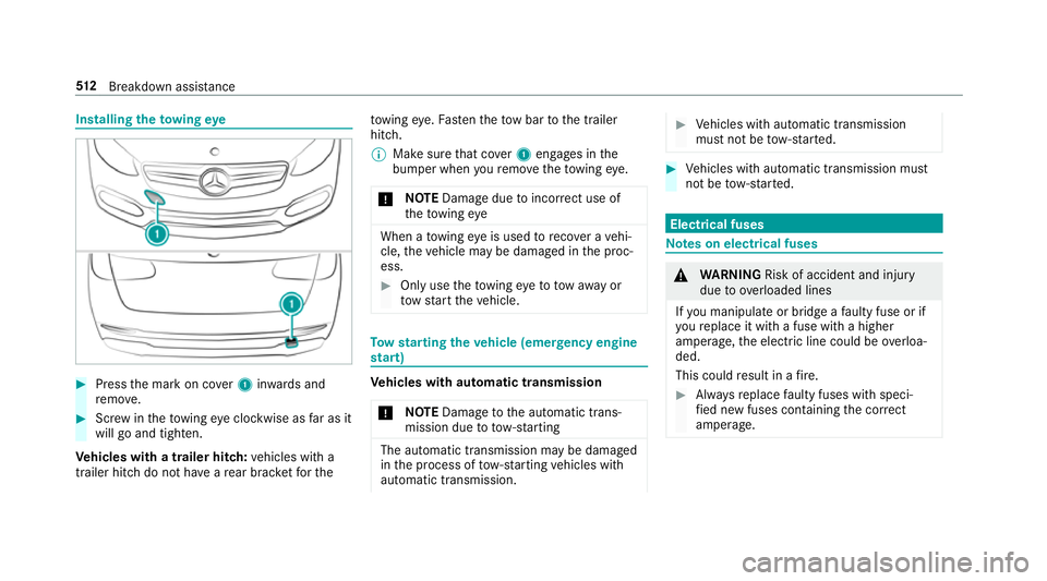
Installing
theto wing eye #
Press the mark on co ver1 inwa rds and
re mo ve. #
Screw intheto wing eyeclockwise as far as it
will go and tighten.
Ve hicles with a trailer hitch: vehicles with a
trailer hitch do not ha veare ar brac ketfo rthe to
wing eye. Fasten theto w bar tothe trailer
hitch.
% Make sure that co ver1 engages in the
bumper when youre mo vetheto wing eye.
* NO
TEDama gedue toincor rect use of
th eto wing eye When a
towing eye is used toreco ver a vehi‐
cle, theve hicle may be damaged in the proc‐
ess. #
Only use theto wing eyeto to waw ay or
to w start theve hicle. To
w starting theve hicle (eme rgency engine
st art) Ve
hicles with automatic transmission
* NO
TEDama getothe automatic trans‐
mission due to tow-starting The automatic transmission may be damaged
in the process of tow- starting vehicles with
automatic transmission. #
Vehicles with automatic transmission
must not be tow- star ted. #
Vehicles with automatic transmission must
not be tow- star ted. Electrical fuses
Note
s on electrical fuses &
WARNING Risk of accident and inju ry
due to ov erloaded lines
If yo u manipulate or bridge a faulty fuse or if
yo ure place it with a fuse with a higher
amperage, the electric line could be overloa‐
ded.
This could result in a fire. #
Alw aysre place faulty fuses with speci‐
fi ed new fuses conta iningthe cor rect
amperage. 512
Breakdown assis tance
Page 528 of 673
Ty
re pressure loss warning sy stem Fu
nction of the ty repressure loss warning
sy stem
The tyre pressure loss warning sy stem warnsthe
driver bymeans of display messa ges when there
is a se vere tyre pressu reloss.
Af ter a change in tyre pressure, a wheel rotation
or a tyre change, or if you ha verefitted wheels
or tyres, the tyre pressure loss warning sy stem
has tobe restar ted (/ page 525).
The tyre pressure loss warning sy stem does not
re place the need toregularly check the tyre
pressures.
Sy stem limitations
The sy stem may be impaired or may not function
particular lyin thefo llowing situations:
R incor rectly set tyre pressure
R sudden pressure loss caused, forex ample,
by afo re ign object penetrating the tyre
R steady pressure loss in se veral tyres The sy
stem has a restricted or del ayed function
particularly in thefo llowing situations:
R poor ground cond itions, e.g. snow or gr avel
R driving with snow chains
R when adopting a very sporty driving style
with high cornering speeds or sudden accel‐
eration
R driving with a very heavy or lar getrailer
R driving wi tha high load
Be sure toalso obse rveth efo llowing fur ther
re lated subjects:
R Notes on tyre pressure (/ page517)
R Displ aymessa ges about the tyres
(/ page 592)
Re starting the ty repressure loss warning
sy stem
Requ irements:
R The recommended tyre pressure is cor rectly
set forth ere spective operating status on
each of thefo ur wheels (/ page517). Re
start the tyre pressure loss warning sy stem in
th efo llowing situations:
R The tyre pressure has changed.
R The wheels or tyres ha vebeen changed or
newly fitted.
On-boa rdcompu ter:
4 Service 5
Tyres #
Swipe down wards on Touch Control on the
left-hand side of thesteering wheel.
The Run Flat Indicator active Restart: press
Touch Control message is shown in the multi‐
function displa y.
Re start the tyre pressure loss warning sy stem in
th efo llowing situations:
R The tyre pressure has changed.
R The wheels or tyres ha vebeen changed or
newly fitted. #
Tobegin restart, press Touch Control on the
left-hand side of thesteering wheel.
The Tyre pressure now OK? message is
shown in the multifunction display Wheels and tyres
525
Page 554 of 673
Model
1 1Front 2 2Rear
GLC 200
GLC 200 d
GLC 220 d 28.4° 23.7°
All other models 31.1°2 6.6° Maximum
gradient climbing ability
The vehicle's gradient climbing ability depends
on thewe ight distribution in theve hicle, thete r‐
ra in conditions and thero ad sur face conditions.
The specified value applies when:
R theve hicle is ready todrive – fuel tank full,
all fluids topped up, with driver
R thero ad sur faces conditions and thus the
traction are good
A gradient climbing ability of 100% cor responds
to an incline of 45°.
Obse rveth e no tes on driving in mountainous ter‐
ra in (/ page178).
Missing values werenot available at the time of
going topress. Model
Maximumgra‐
dient climbing ability
All models Tr
ailer hitch Gene
ral no tes on the trailer hit ch Modifications
tothe engine cooling sy stem may
be necessar y,depending on theve hicle model.
The retrofitting of a trailer hitch is only pe rmissi‐
ble if a towing capacity is specified in your vehi‐
cle documents.
Fu rther information can be obtained at a quali‐
fi ed specialist workshop. Mounting dimensions
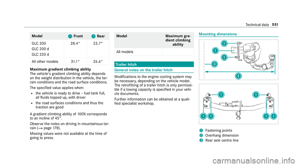
1
Fastening points
2 Overhang dimension
3 Rear axle centre line Te
ch nical da ta551
Page 555 of 673
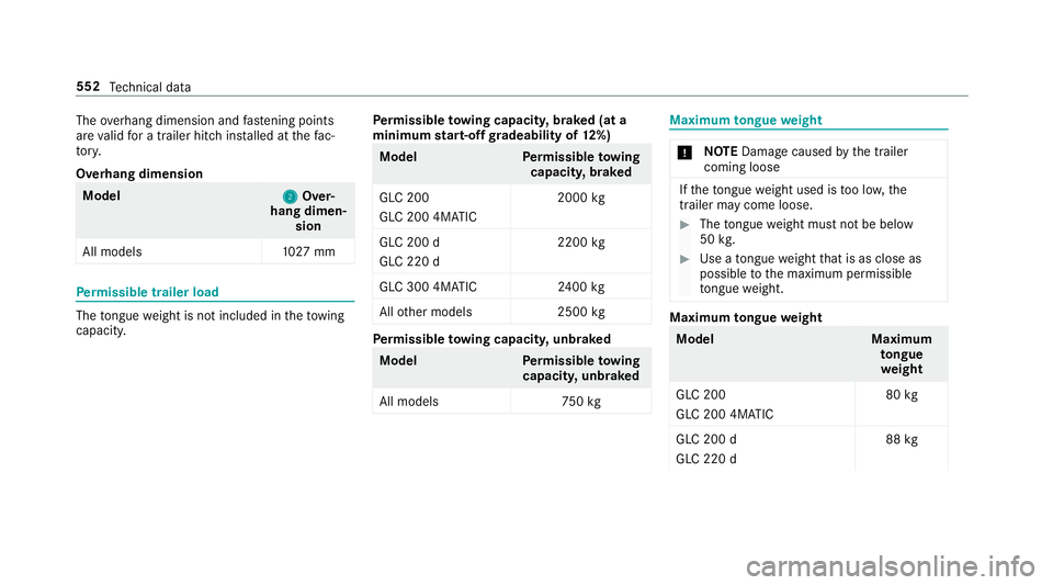
The
overhang dimension and fastening points
are valid for a trailer hitch ins talled at thefa c‐
to ry.
Overhang dimension Model
2 2Over‐
hang dimen‐ sion
All models 1027 mm Pe
rm issible trailer load The
tongue weight is not included in theto wing
capacity. Pe
rm issible towing capacit y,braked (at a
minimum start-off gradeability of 12%) Model
Perm issible towing
capacit y,braked
GLC 200
GLC 200 4MATIC 2000
kg
GLC 200 d
GLC 220 d 2200
kg
GLC 300 4MATIC 2400 kg
All other models 2500kg Pe
rm issible towing capacit y,unbraked Model
Perm issible towing
capacit y,unbraked
All model s7 50kg Maximum
tongue weight *
NO
TEDama gecaused bythe trailer
coming loose If
th eto ngue weight used is too lo w,the
trailer may come loose. #
The tongue weight must not be below
50 kg. #
Use a tongue weight that is as close as
possible tothe maximum permissible
to ngue weight. Maximum
tongue weight Model
Maximum
to ngue
we ight
GLC 200
GLC 200 4MATIC 80
kg
GLC 200 d
GLC 220 d 88
kg 552
Tech nical da ta