2019 MERCEDES-BENZ GLB SUV inflation pressure
[x] Cancel search: inflation pressurePage 507 of 689
R
smoke which smells like rubber
R continuous ESP ®
inter vention
R crac ksin tire side walls #
After driving in emergency mode ha ve
th erims checkedby aqu alified special‐
ist workshop with rega rd totheir fur ther
use. #
The defective tire must be replaced in
eve rycase. Wi
th MOExtended tyres (run-flat tyres), you can
continue todrive your vehicle even if there is a
tot al loss of pressure in one or more tyres. How‐
eve r,th e tyre af fected must not show any clearly
visible damage.
Yo u can recognise MOExtended tyres bythe
MOExtended marking which appears on the side
wa ll of the tyre.
Ve hicles with tyre pressure loss warning sys‐
te m: MOExtended tyres may only be used in
conjunction wi than activated tyre pressure loss
wa rning sy stem. Ve
hicles with tyre pressure monitoring sys‐
te m: MOExtended tyres may only be used in
conjunction wi than activated tyre pressure mon‐
itoring sy stem.
If a pressure loss warning message appears in
th e multifunction displa y,proceed as follo ws:
R Check the tyre for dama ge.
R If driving on, obser vethefo llowing no tes.
Driving distance possible in emer gency
mode af ter the pressure loss warning: Load condition Driving distance pos‐
sible in emergency
mode
Pa rtially laden 80 km
Fu lly laden 30 km The driving dis
tance possible in emergency
mode may vary depending on the driving style.
Obser vethe maximum permissible speed of
80 km/h. If a tyre has gone
flat and cannot be replaced
with an MOEx tended tyre, you can use a stand‐
ard tyre as a temp orary measure. TIREFIT kit
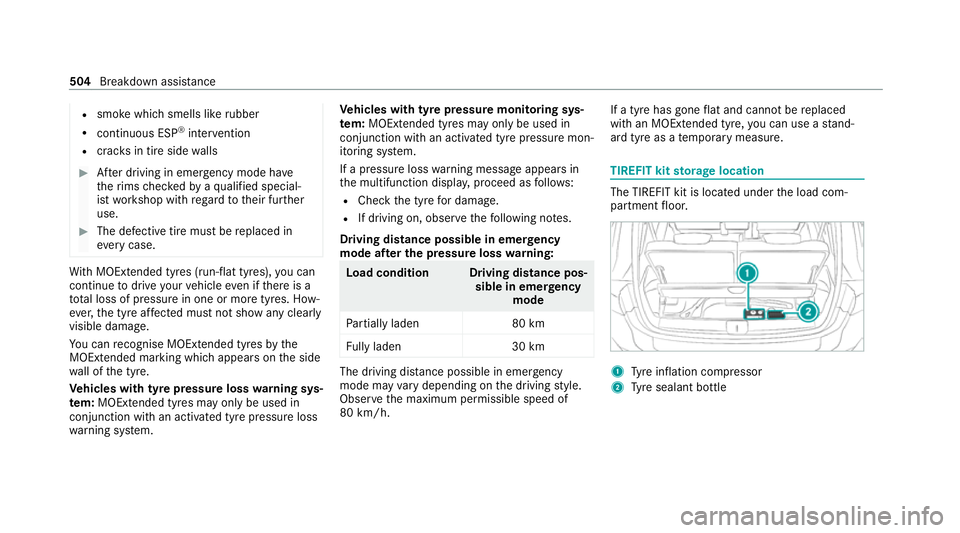
storage location The TIREFIT kit is located under
the load com‐
partment floor. 1
Tyre inflation compressor
2 Tyre sealant bottle 504
Breakdown assis tance
Page 508 of 689
%
You can find information on the po wer cate‐
gory (LK) and/or electrical data on the back
of the tyre inflation compressor:
R LK2 – 12V/15 A,180W, 0.8 kg
At a dis tance of appr oximately 1 m tothe
tyre inflation compressor and appr oximately
1. 6 m abo vethe ground, thefo llowing sound
pressure le vels apply:
R Emission sound pressure le vel L
PA
83 dB (A)
R Sound po wer le vel L
WA 91
dB (A)
The tyre inflation compressor is mainte‐
nance-free. If there is a malfunction, please
contac t aqualified specialist workshop. Using
the TIREFIT kit Re
quirements:
Re quired tools:
R Tyre sealant bottle
R TIREFIT sticker R
Sticke r with de tails of the maximum permis‐
sible speed
R Tyre inflation compressor
R Gloves
TIREFIT kit storage location: (/ page 504)
Yo u can use TIREFIT tyre sealant toseal per fora‐
tion dama geof up to4 mm, particular lythose in
th e tyre conta ct surface. You can use TIREFIT in
outside temp eratures down to-20 °C. &
WARNING Risk of accident when using
tyre sealant
In thefo llowing situations in particular, the
tyre sealant is unable toprov ide suf ficient
breakdown assis tance, as it is unable toseal
th e tyre properly:
R there are cuts or punctures in the tyre
lar gerth an those pr eviously mentioned.
R the wheel rim is dama ged.
R you ha vedriven at very low tyre pres‐
sures or on a flat tyre. #
Do not drive on. #
Consult a qualified specialist workshop. &
WARNING Risk of inju ryand poisoning
from tyre sealant
Ty re sealant is hazardous tohealth and cau‐
ses ir rita tion. Do not allow it tocome into
contact wi thyour skin, eyes or clo thing, and
do not swallow it. Do not inhale any vapours.
Ke ep the tyre sealant away from children.
Obser vethefo llowing if you come into con‐
ta ct wi th the tyre sealant: #
Rinse off the tyre sealant from your skin
using water immediatel y. #
If tyre sealant gets into your eyes, thor‐
oughly rinse them using clean water
immediatel y. #
If tyre sealant has been swallowe d,
th oroughly rinse out your mouth imme‐
diately and drink plenty of water.Do not
induce vomiting and seek medical
attention immediately. Breakdown assi
stance 505
Page 510 of 689
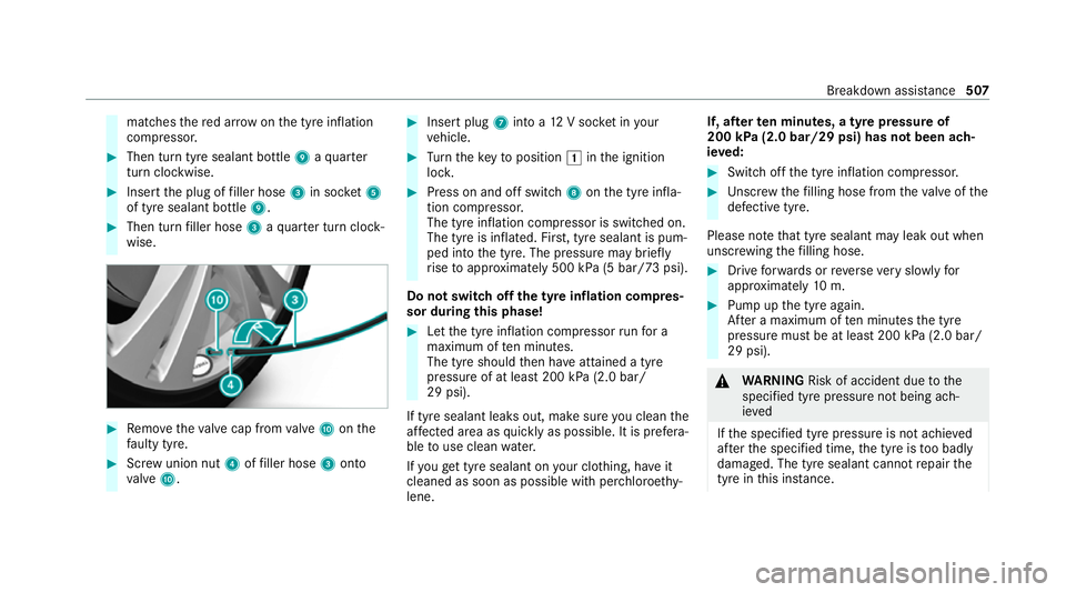
matches
there d ar row on the tyre inflation
compressor. #
Then turn tyre sealant bottle 9aqu arter
turn clo ckwise. #
Insert the plug of filler hose 3in soc ket5
of tyre sealant bottle 9.#
Then turn filler hose 3aqu arter turn clock‐
wise. #
Remo vetheva lve cap from valve A onthe
fa ulty tyre. #
Screw union nut 4offiller hose 3onto
va lve A. #
Insert plug 7into a 12V soc ket in your
ve hicle. #
Turn theke yto position 1inthe ignition
loc k. #
Press on and off switch 8onthe tyre infla‐
tion compressor.
The tyre inflation compressor is switched on.
The tyre is inflated. Fir st, tyre sealant is pum‐
ped into the tyre. The pressure may brief ly
ri se toappr oximately 500 kPa (5 bar/73 psi).
Do not switch off the ty reinflation compres‐
sor during this phase! #
Let the tyre inflation compressor runfo r a
maximum of ten minu tes.
The tyre should then ha veattained a tyre
pressure of at least 200 kPa (2.0 bar/
29 psi).
If tyre sealant leaks out, make sure you clean the
af fected area as quickly as possible. It is prefera‐
ble touse clean water.
If yo uge t tyre sealant on your clo thing, ha veit
cleaned as soon as possible with per chloroe thy‐
lene. If, af
terte n minutes, a tyre pressure of
200 kPa (2.0 bar/29 psi) has not been ach‐
ie ve d: #
Switch off the tyre inflation compressor. #
Unscr ew thefilling hose from theva lve of the
defective tyre.
Please no tethat tyre sealant may leak out when
unscr ewing thefilling hose. #
Drive forw ards or reve rseve ry slowly for
appr oximately 10m. #
Pump up the tyre again.
Af ter a maximum of ten minu testh e tyre
pressure must be at least 200 kPa (2.0 bar/
29 psi). &
WARNING Risk of accident due tothe
specified tyre pressure not being ach‐
ie ved
If th e specified tyre pressure is not achie ved
af te rth e specified time, the tyre is too badly
damaged. The tyre sealant cannot repair the
tyre in this ins tance. Breakdown assi
stance 507
Page 511 of 689
Damaged tyres and a tyre pressure
that is
to o low can significantly impair braking and
handling characteristics. #
Do not drive on. #
Consult a qualified specialist workshop. *
NO
TEStaining from leaking tyre sealant Af
ter use, excess tyre sealant may leak out
from thefilling hose. #
Therefore, place thefilling hose in the
plastic bag that con tained the TIREFIT
kit. If, af
terte n minutes, a tyre pressure of
200 kPa (2.0 bar/29 psi) has been achie ved: #
Switch off the tyre inflation compressor. #
Unscr ew thefilling hose from theva lve of the
defective tyre.
Please no tethat tyre sealant may leak out when
unscr ewing thefilling hose. &
WARNING Risk of accident from driving
wi th sealed tyres
A tyre temp orarily sealed with tyre sealant
impairs driving characteristics and is not
suitable for higher speeds. #
Adapt your driving style according lyand
drive carefull y. #
Do not exceed the maximum speed
limit with a tyre that has been repaired
using tyre sealant. #
Obser vethe maximum permissible speed for
a tyre sealed with tyre sealant 80 km/h. #
The sticke r with de tails of the maximum per‐
missible speed must be af fixe dto the instru‐
ment clus ter where it can be easi lyseen by
th e driver.
* NO
TEStaining from leaking tyre sealant Af
ter use, excess tyre sealant may leak out
from thefilling hose. #
Therefore, place thefilling hose in the
plastic bag that con tained the TIREFIT
kit. +
ENVIRONMEN
TALNO TEEnvironmental
pollution caused byenvironmen tally ir re‐
sponsible disposal Ty
re sealant contains polluta nts. #
Have the tyre sealant bottle disposed of
professionall y,e.g. at a Mercedes-Benz
Service Centre. #
Stow th e tyre sealant bottle, the tyre inflation
compressor and thewa rning triangle. #
Pull away immediatel y. #
Stop driving af ter appro ximately ten minu tes
and check the tyre pressure using the tyre
inflation compressor.
The tyre pressure must now be at least
13 0 kPa (1.3 bar/19 psi). 508
Breakd own assi stance
Page 512 of 689
&
WARNING Risk of accident due tothe
specified tyre pressure not being ach‐
ie ved
If th e specified tyre pressure is not achie ved
af te r a brief drive, the tyre is too badly dam‐
aged. The tyre sealant cannot repair the tyre
in this ins tance.
Dama ged tyres and a tyre pressure that is
to o low can significantly impair braking and
handling characteristics. #
Do not drive on. #
Consult a qualified specialist workshop. Countries
that ha veMercedes-Benz
Service24h: you will find a sticke r with thete le‐
phone number, e.g. on the B‑pillar on the driver's
side. #
Cor rect the tyre pressure if it is still at least
13 0 kPa (1.3 bar/19 psi). See the tyre pres‐
sure table on the fuel filler flap forva lues. #
Toincrease the ty repressure: switch on
th e tyre inflation compressor. #
Toreduce the tyre pressure: remo vethe
tyre sealant bottle from the tyre inflation
compressor. #
Insert thefiller hose in the soc ket of the tyre
inflation compressor and turn it a quarter
turn clo ckwise. #
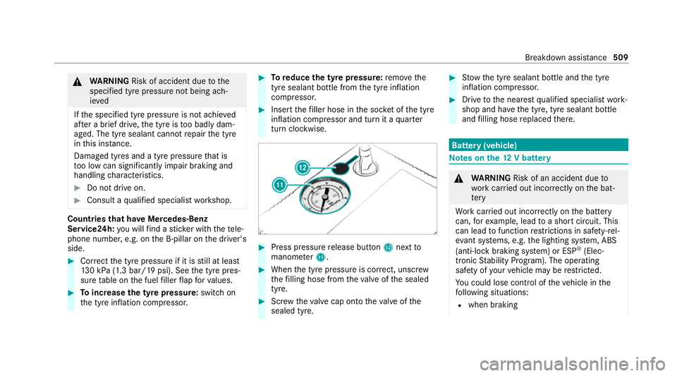
Press pressure release button Cnext to
manome terB. #
When the tyre pressure is cor rect, unscr ew
th efilling hose from theva lve of the sealed
tyre. #
Screw theva lve cap onto theva lve of the
sealed tyre. #
Stow th e tyre sealant bottle and the tyre
inflation compressor. #
Drive tothe nearest qualified specialist work‐
shop and ha vethe tyre, tyre sealant bottle
and filling hose replaced there. Batte
ry(vehicle) Note
s onthe12 V battery &
WARNING Risk of an accident due to
wo rkcar ried out incor rectly on the bat‐
te ry
Wo rkcar ried out incor rectly on the battery
can, forex ample, lead toa short circuit. This
can lead tofunction restrictions in saf ety-re l‐
eva nt sy stems, e.g. the lighting sy stem, ABS
(anti-lock braking sy stem) or ESP ®
(Elec‐
tronic Stability Prog ram). The operating
saf ety of your vehicle may be restricted.
Yo u could lose cont rol of theve hicle in the
fo llowing situations:
R when braking Breakdown assis
tance 509
Page 548 of 689
Re
place the emer gency spa rewheel af ter six
ye ars at the latest, rega rdless of wear.
% Ve
hicles with a tyre pressure loss warn‐
ing sy stem: if an emer gency spa rewheel is
fi tted the tyre pressure loss warning sy stem
cann otfunction reliabl y.Only restart the sys‐
te m again when the emer gency spa rewheel
has been replaced with a new wheel.
Ve hicles with a tyre pressure monitoring
sy stem: if an emer gency spa rewheel is fit‐
te dth e tyre pressure monitoring sy stem can‐
not function reliabl y.Fo r a few minutes af ter
an emer gency spa rewheel is fitted, the sys‐
te m may still display the tyre pressure of the
re mo ved wheel. Only restart the sy stem
again when the emer gency spa rewheel has
been replaced with a new wheel.
Be sure toalso obse rveth efo llowing fur ther
re lated subjects:
R Notes on tyre pressure (/ page 525)
R Tyre pressure table (/ page 526) Re
moving the eme rgency spa rewheel The deflated eme
rgency spare wheel is secured
in the emer gency spa rewheel bag in the load
compartment and is secured tothe adjus table
load compartment floor in the lo wer position. #
Obser vethe information on mounting tyres
(/ page 534). #
Open theta ilgate. #
Detach the securing stra ps. #
Unhook there taining spring hooks of the
securing stra ps from the brac kets. #
Remo vethe emer gency spa rewheel bag with
th e emer gency spa rewheel. #
Open the emer gency spa rewheel bag and
re mo vethe emer gency spa rewheel. Inflating
the emer gency spare wheel *
NO
TEOverheating due tothe tyre infla‐
tion compressor running too long #
Do not runth e tyre inflation compres‐
sor for longer than ten minu tes without
inter ruption. Re
quirements:
R Comply with the manufacturer's saf ety no tes
on thest icke r of the emer gency spa rewheel
and on the tyre inflation compressor.
R Remo vethe tyre inflation compressor from
th estow age space under the luggage com‐
partment floor (/ page 504). Wheels and tyres
545
Page 549 of 689
#
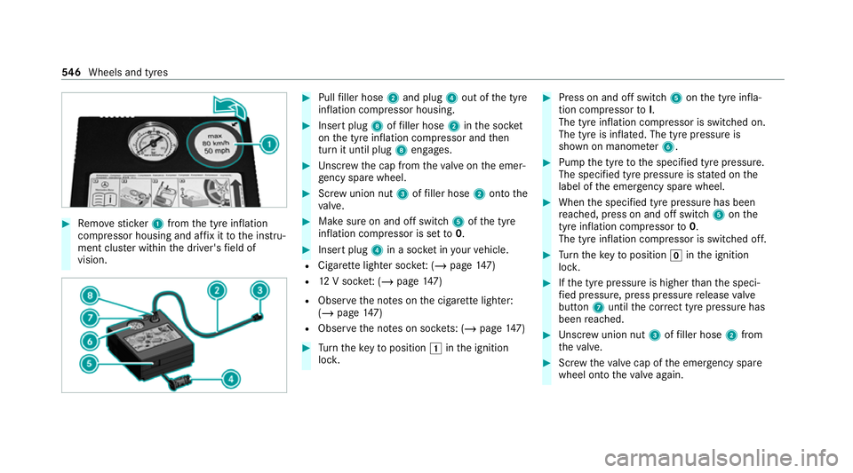
Remo vesticke r1 from the tyre inflation
compressor housing and af fix it tothe instru‐
ment clus ter within the driver's field of
vision. #
Pull filler hose 2and plug 4out of the tyre
inflation compressor housing. #
Insert plug 8offiller hose 2inthe soc ket
on the tyre inflation compressor and then
turn it until plug 8engages. #
Unscr ew the cap from theva lve on the emer‐
ge ncy spa rewheel. #
Screw union nut 3offiller hose 2onto the
va lve. #
Make sure on and off switch 5ofthe tyre
inflation compressor is set to0. #
Insert plug 4in a soc ket in your vehicle.
R Cigar ette lighter soc ket: ( / page 147)
R 12V soc ket: ( / page 147)
R Obse rveth e no tes on the cigar ette lighter:
(/ page 147)
R Obse rveth e no tes on soc kets: (/ page 147) #
Turn theke yto position 1inthe ignition
loc k. #
Press on and off switch 5onthe tyre infla‐
tion compressor toI.
The tyre inflation compressor is switched on.
The tyre is inflated. The tyre pressure is
shown on manome ter6. #
Pump the tyre tothe specified tyre pressure.
The specified tyre pressure is stated on the
label of the emer gency spa rewheel. #
When the specified tyre pressure has been
re ached, press on and off swit ch5 onthe
tyre inflation compressor to0.
The tyre inflation compressor is switched off. #
Turn theke yto position ginthe ignition
loc k. #
Ifth e tyre pressure is higher than the speci‐
fi ed pressure, press pressure release valve
bu tton 7until the cor rect tyre pressure has
been reached. #
Unscr ew union nut 3offiller hose 2from
th eva lve. #
Screw theva lve cap of the emer gency spa re
wheel onto theva lve again. 546
Wheels and tyres
Page 680 of 689
Fo
lding the ball neck out/in ................2 88
Gene ral no tes ...................................... 563
Mounting dimensions .......................... 563
No tes .................................................. 288
Overhang dimension ........................... 563
Soc ket ................................................. 290
To ngue weight .................................... .565
To wing capacity .................................. .564
Tr ailer operation
Ac tive Blind Spot Assi st....................... 284
Ac tive Lane Keeping Assist ................. 285
Bicycle rack ......................................... 291
Coupling up/uncoupling a trailer ........ 290
Fo lding the ball neck out/in ................2 88
No tes .................................................. 288
Soc ket ................................................. 290
Tr ailer stabilisation
Fu nction/no tes ................................... 230
Tr ansfer redve hicle data
Android Auto ....................................... 446
Apple CarPl ay®
.................................... 446
Tr ansmission (problem) .......................... 208
Tr ansmission position display ...............203 Tr
anspo rting
Ve hicle .................................................5 17
Tr im element (Care) ................................ 499
Tr ip
Menu (on-board computer) .................. 301
Tr ip computer
Displaying ............................................ 301
Re setting ............................................. 302
Tr ip distance ............................................ 301
Displaying ............................................ 301
Re setting ............................................. 302
Tr ip me ter
see Trip dis tance
Tu neIn
Calling up ............................................ 465
Calling up thest ation list (category
last selec ted) .......................................4 68
Deleting stations ................................ .468
Logging out ......................................... 468
Overview ............................................. 467
Re gis tering .......................................... 468
Saving stations .................................... 468
Selecting and connecting toast ation
............................................................ .467 Selecting
stre am ................................ .468
Setting options ................................... .468
Te rm s of use ........................................4 68
Tu rn signal indicator
see Turn signal lights
Tu rn signal lights .....................................1 57
Changing bulbs (rear) .......................... 167
Switching on/off ................................. 157
Tw o-w ayradios
Fr equencies ......................................... 549
No tes on ins tallation .......................... .548
Tr ansmission output (maximum) ........ .549
Ty re inflation compressor
see TIREFIT kit
Ty re pressure ........................................... 526
Checking (ty repressure monitoring
sy stem) ............................................... 528
No tes .................................................. 525
Re starting the tyre pressure loss
wa rning sy stem ................................... 533
Re starting the tyre pressure monitor‐
ing sy stem ...........................................5 28
TIREFIT kit .......................................... .505 Index
677