2019 MERCEDES-BENZ GLB SUV battery
[x] Cancel search: batteryPage 158 of 689
Exterior lighting
Note
s on adjusting the lights when driving
abroad It is not necessary
toadjust the headlamps. The
legal requirements are also met in countries in
which traf fic drives on theot her side of thero ad. Information about lighting sy
stems and your
re sponsibility The
various lighting sy stems of theve hicle are
only aids. The driver of theve hicle is responsible
fo r cor rect vehicle illumination in accordance
with the pr evailing light and visibility conditions,
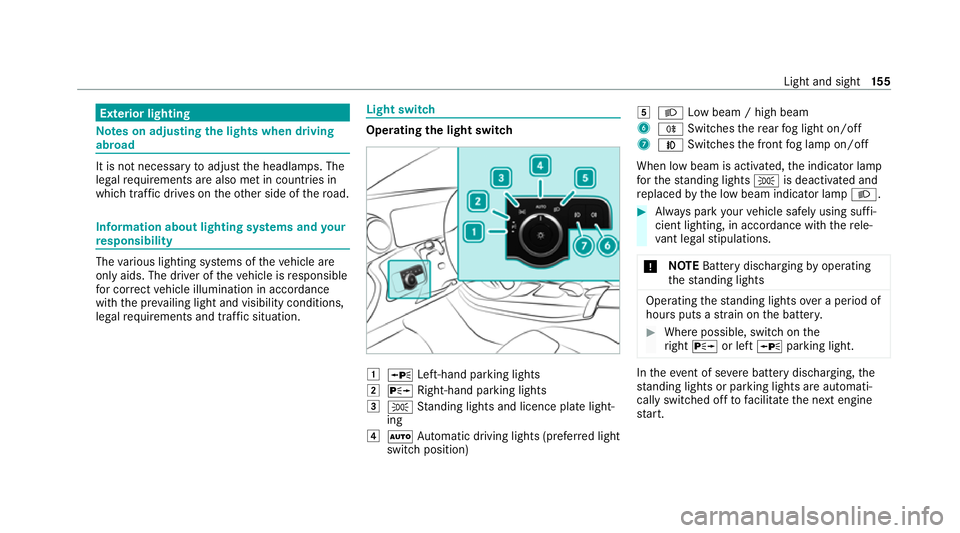
legal requirements and traf fic situation. Light switch
Ope
rating the light switch 1
W Left-hand pa rking lights
2 X Right-hand parking lights
3 T Standing lights and licence plate light‐
ing
4 Ã Automatic driving lights (prefer red light
switch position) 5
L Low beam / high beam
6 R Switches there ar fog light on/off
7 N Switches the front fog lamp on/off
When low beam is activated, the indicator lamp
fo rth est anding lights Tis deactivated and
re placed bythe low beam indicator lamp L. #
Alw ays park your vehicle safely using suf fi‐
cient lighting, in acco rdance with there le‐
va nt le galst ipulations.
* NO
TEBattery discharging byoperating
th est anding lights Operating
thest anding lights over a period of
hours puts a stra in on the batter y. #
Where possible, switch on the
ri ght X or left Wparking light. In
theeve nt of se vere battery discharging, the
st anding lights or parking lights are automati‐
cally swit ched off tofacilitate the next engine
st art. Light and sight
15 5
Page 175 of 689
&
WARNING Risk of accident due tomis‐
judgement of dis tances when using the
outside mir ror
The outside mir rors reflect objects on a
smaller scale. The objects in view are in fact
closer than they appear.
As a result, you may misjud gethe dis tance
between you and thero ad user driving
behind you, e.g. when changing lanes. #
Therefore, alw ays look over your shoul‐
der in order toensure that you are
aw are of the actual dis tance between
yo u and thero ad users driving behind
yo u. #
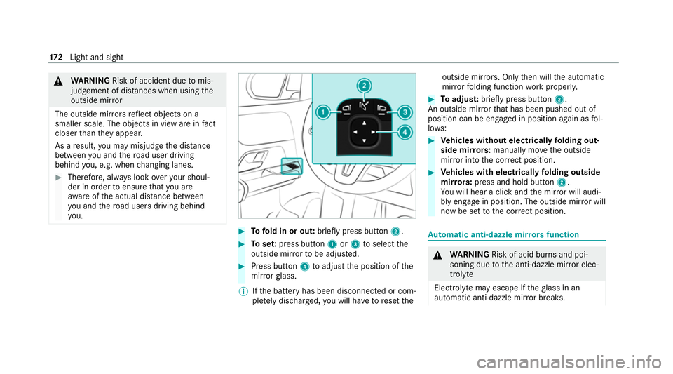
Tofold in or out: brieflypress button 2. #
Toset:press button 1or3 toselect the
outside mir rorto be adjus ted. #
Press button 4toadjust the position of the
mir rorgl ass.
% Ifth e battery has been disconnected or com‐
ple tely discharged, you will ha vetoreset the outside mir
rors. Only then will the automatic
mir rorfo lding function workproperly. #
Toadjus t:briefly press button 2.
An outside mir rorth at has been pushed out of
position can be engaged in position again as fol‐
lo ws: #
Vehicles without electrical lyfolding out‐
side mir rors: manually mo vethe outside
mir ror into the cor rect position. #
Vehicles with electrical lyfolding outside
mir rors: press and hold button 2.
Yo u will hear a click and the mir ror will audi‐
bly engage in position. The outside mir ror will
now be set tothe cor rect position. Au
tomatic anti-dazzle mir rors function &
WARNING Risk of acid bu rns and poi‐
soning due tothe anti-dazzle mir ror elec‐
trolyte
Electrolyte may escape if theglass in an
automatic anti-dazzle mir ror breaks. 17 2
Light and sight
Page 182 of 689
R
The air inside theve hicle cannot be cooled
down totemp eratures below the outside
te mp erature.
R Ifth e outside temp erature changes, ventila‐
tion mode au tomatical lyswitches toheating
mode or heating mode automatically
switches toventilation mode.
The stationary heater and theex haust gas outlet
are situated in front of theright-hand front
wheel.
Switching thest ationary heater/stationary
ve ntilation on/off via the control panel &
DANG ER Risk of fata l injury due topoi‐
sonous exhaust gases
If th eta ilpipe is bloc ked or suf ficient ventila‐
tion is not possible, poisonous exhaust gases
such as carbon monoxide may enter theve hi‐
cle. This is the case in enclosed spaces or if
th eve hicle gets stuck in sn ow,fo rex ample. #
Alw ays switch thest ationary heater off
in enclosed spaces without an air
ex traction sy stems, e.g. in garage s. #
Keep theta ilpipe and the area around
th eve hicle free from snow when the
engine or thest ationary heater are run‐
ning. #
Open a window on the windward side of
th eve hicle toensure an adequate sup‐
ply of fresh air. &
WARNING Risk offire due tohot station‐
ary heater components
When thest ationary heater is swit ched on,
parts of theve hicle can become very hot,
e.g. thest ationary heater exhaust sy stem.
Flammable materials such as lea ves, grass or
twigs may ignite if they come into contact
wi th:
R hot parts of thest ationary heater exhaust
sy stem
R theex haust gas itself
There is a risk of fire. #
When thest ationary heater is swit ched
on, make sure that: R
hot vehicle parts do not come into
contact with flammable materials.
R theex haust gas can flow out of the
st ationary heater exhaust pipe
unhindered.
R theex haust gas does not come into
contact with flammable materials. *
NO
TEBattery discharge caused bysta‐
tionary heater or stationary ventilation
operation Ope
rating thest ationary heater or stationary
ve ntilation drains the batter y. #
After heating or ventilating theve hicle
twice, drive for a longer period of time. Re
quirements:
R The fuel tank has been filled toat least Õ. Climate control
17 9
Page 185 of 689
Fu
rther possible displa ys:
R Time: activated departure time.
R Zero minutes: theru nning time forth est a‐
tionary heater is inc reased, as the engine has
not yetre ached operating temp erature when
it is star ted.
R OFF: thest ationary heater/ stationary venti‐
lation is switched off.
Re placing the remo tecont rol bat tery (sta‐
tiona ryheater) &
DANG ER Serious damage tohealth
caused byswallowing batteries
Batteries contain toxic and cor rosive sub‐
st ances. Swallowing bat teries may cause
serious damage tohealth.
There is a risk of fata l injur y. #
Keep batteries out of there ach of chil‐
dren. #
If batteries are swallo wed, seek medical
attention immediately. +
ENVIRONMEN
TALNO TEEnvironmental
dama gedue toimproper disposal of bat‐
te ries Batteries conta
intoxic and cor ro‐
sive subs tances. #
Ta
ke dischar ged batteries to a
qu alified specialist workshop or to a
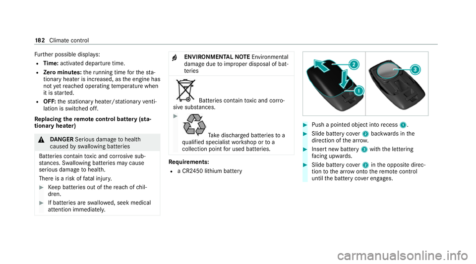
collection point for used batteries. Re
quirements:
R a CR2450 lithium battery #
Push a pointed object into recess 1. #
Slide battery co ver2 backwards in the
direction of the ar row. #
Insert new battery 3with the lettering
fa cing up wards. #
Slide battery co ver2 inthe opposite direc‐
tion tothe ar row onto there mo tecontrol
until the battery co ver engages. 18 2
Climate cont rol
Page 186 of 689
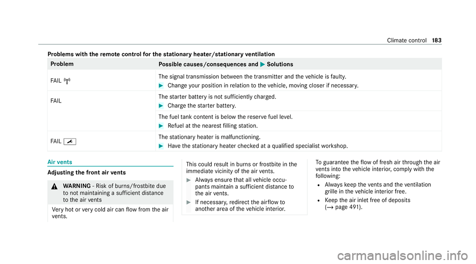
Problems with
there mo tecont rolfo r the stationary heater/stationary ventilation Problem
Possible causes/consequences and M
MSolutions
FA IL¨ The signal transmission between
the transmit ter and theve hicle is faulty. #
Chan geyour position in relation totheve hicle, moving closer if necessar y.
FA IL The
star ter battery is not suf ficiently charge d. #
Char gethest ar ter batter y.
The fuel tank content is below there ser vefuel le vel. #
Refuel at the nearest filling station.
FA IL¯ The
stationary heater is malfunctioning. #
Have thest ationary heater checked at a qualified specialist workshop. Air
vents Ad
justing the front air vents &
WARNING ‑ Risk of bu rns/frostbite due
to not maintaining a su fficient dis tance
to the air vents
Ve ry hot or very cold air can flow from the air
ve nts. This could
result in burns or frostbite in the
immediate vicinity of the air vents. #
Alw ays ensure that all vehicle occu‐
pants maintain a suf ficient di stance to
th e air vents. #
If necessa ry,re direct the air flow to
ano ther area of theve hicle interior. To
guarantee theflow of fresh air thro ugh the air
ve nts into theve hicle interior, comply with the
fo llowing:
R Alw ayske ep theve nts and theve ntilation
grille in theve hicle interior free.
R Keep the air inlet free of deposits
(/ page 491). Climate control
18 3
Page 192 of 689
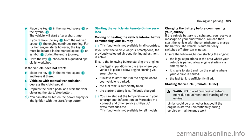
#
Place theke y1 inthe mar ked space 2on
th e symbol 3.
The vehicle will start af ter a short time.
If yo ure mo vetheke y1 from the mar ked
space 2the engine continues running. For
fur ther engine starts ho wever,th eke y1
must be located in the mar ked space 2on
symbol 3during the entire journe y. #
Have theke y1 checked at a qualified spe‐
cialist workshop.
If th eve hicle does not star t: #
place theke y1 inthe mar ked space 2
and lea veitth ere. #
Vehicles with manual transmission:
depress the clutch pedal. #
Depress the brake pedal and start theve hi‐
cle using thest art/ stop button.
% You can also swit chon the po wer supp lyor
th e ignition with thest art/ stop button. St
arting theve hicle via Remo teOnline serv‐
ices Cooling or heating
theve hicle interior before
commencing your journey
% This function is not available in all countries.
If yo ustart theve hicle via your smartphone, the
pr ev iously selec ted air conditioning adjustment
is active.
Ensure thefo llowing before starting the engine:
R the legal stipulations in the area where your
ve hicle is par ked allow engine starting via
smartphone.
R it is safe tostart and runth e engine where
yo ur vehicle is par ked.
R the fuel tank is su fficiently filled.
R thest ar ter battery is suf ficiently charge d.
% You can also set thete mp erature with your
smartphone. In form ation on Mercedes me
connect and other services: https://
www.mercedes.me
This function is not available for all models. Charging
the bat tery before commencing
yo ur journey
If th eve hicle battery is dischar ged, youre cei ve a
messa geon your smartphone. You can then
st art theve hicle with the smartphone tocharge
th e batter y.The vehicle is automatically
switched off af terte n minu tes.
Ensure thefo llowing before starting the engine:
R the legal stipulations in the area where your
ve hicle is par ked allow engine starting via
smartphone.
R it is safe tostart and runth e engine where
yo ur vehicle is par ked.
R the fuel tank is su fficiently filled.
St arting theve hicle (Remo teOnline) &
WARNING Risk of crushing or entrap‐
ment due tounin tentional starting of the
engine
Limbs could be crushed or trapped if the
engine is star ted unintentionally during
service or maintenance work. Driving and pa
rking 18 9
Page 227 of 689
R
The electric parking brake is not applied. Note
s on parking up theve hicle If
yo u lea vetheve hicle par ked up for longer than
six weeks, it may suf fer dama gethro ugh disuse.
The 12V battery may also be impaired or dam‐
aged byheavy discharging.
% Further information can be obtained at a
qu alified specialist workshop. St
andby mode (extension of the star ter bat‐
te ry 's period out of use) St
andby mode function
% This function is not available for all models.
If standby mode is activated, ene rgy loss will be
minimised during extended pe riods of non-oper‐
ation.
St andby mode is characterised bythefo llowing:
R thest ar ter battery is preser ved.
R the maximum non-operational time appears
in the media displa y. R
the connection toonline services is inter rup‐
te d.
R theAT A (anti-theft alarm sy stem) is not avail‐
able.
R the interior pr otection and tow- aw ay protec‐
tion functions are not available.
R the function for de tecting damage on a
pa rked vehicle is not available.
If th efo llowing conditions are fulfilled, standby
mode can be activated or deactivated using the
multimedia sy stem:
R the engine is switched off.
R the ignition is switched on.
Exceeding theve hicle's displa yed non-opera‐
tional time may cause incon venience, i.e. it can‐
not be guaranteed that thest ar ter battery will
re liably start the engine.
The star ter battery must be charge dfirs t in the
fo llowing situations:
R The vehicle's non-operational time must be
ex tended. R
The Battery charge insufficient for standby
mode messa geappears in the media displa y.
% Standby mode is automatically deactivated
when the ignition is switched on.
Ac tivating/deactivating standby mode (park‐
ing up theve hicle)
Re quirements:
R The engine is switched off.
Multimedia sy stem:
4 © 5
Settings 5
Vehicle #
Switch Standby mode on or off.
When you activate the function, a prom pt
appears. #
Select Yes.
St andby mode is activated. Driving and driving saf
ety sy stems Driving sy
stems and your responsibility Yo
ur vehicle is equipped with driving sy stems
which assist you in driving, parking and manoeu‐
vring theve hicle. The driving sy stems are aids 224
Driving and parking
Page 293 of 689
#
Remo vethe co ver cap from the ball head and
st ore it in a safe place.
Make sure that the ball on the ball neck is clean.
Check that it is either greased or dr y (grease-
free), depending on the instructions forthe
traile r.
Fo lding the ball neck in #
Pull release switch 2until the ball neck
unloc ks.
The ball neck will fold up under there ar
bumper.
Indicator lamp 1will flash. #
Push the ball neck in the direction of the
ar row until it en gage s audibly behind the
bumper.
Indicator lamp 1will go out and the mes‐
sage on the multifunction display will disap‐
pear.
Obser vethe information on the displa yson the
instrument clus ter:
R Indicator and warning lamps (/ page 623)
R Display messages (/ page 566) Coupling up / uncoupling a trailer
Re
quirements:
R The ball neck is extended and engaged in a
secu rely loc ked position
Tr ailers with a 7-pin plug can be connec tedto
th eve hicle with thefo llowing adap ters:
R Adapter plug
R Adapter cable
The trailer will be cor rectly de tected bytheve hi‐
cle only if thefo llowing conditions are me t:
R The trailer is connected cor rectly
R The trailer lighting sy stem is in working order
The functions of thefo llowing sy stems are af fec‐
te dby a cor rectly connected traile r:
R Active Lane Keeping Assist
R ESP ®
trailer stabilisation
R Parking Assist PARKTRONIC
R Active Parking Assist
R Blind Spot Assist or Active Blind Spot Assi st
R Drive AwayAssi st R
Cross Traf fic Alert
R Reversing camera
R 360° camera
Coupling up a trailer
* NO
TEDama getothe battery due tofull
dischar ge Charging
the trailer battery using the po wer
supply of the trailer can damage theve hicle
batter y. #
Do not use theve hicle's po wer supply
to charge the trailer batter y. #
Remo vethe co ver from the ball head and
st ore it in a safe place (/ page126). #
Position the trailer on a le vel sur face behind
th eve hicle and couple it up totheve hicle. 290
Driving and parking