2019 MERCEDES-BENZ CLA COUPE seats
[x] Cancel search: seatsPage 127 of 645
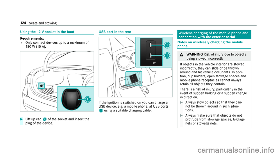
Using
the12 V so cket inthe boot Re
quirements:
R Only connect devices up toa maximum of
18 0 W (15 A). #
Lift up cap 1ofthe soc ket and insert the
plug of the device. USB port in
there ar If
th e ignition is switched on you can charge a
USB device, e.g. a mobile phone, at USB ports
1 using a suitable charging cable. Wire
lesscharging of the mobile phone and
connection with theex terior aerial Note
s on wirelessly charging the mobile
phone &
WARNING Risk of inju rydue toobjects
being stowed inco rrectly
If objects in theve hicle interior are stowed
incor rectly, they can slide or be thrown
around and hit vehicle occupants. In addi‐
tion, cup holders, open stowage spaces and
mobile phone recep tacles cannot al ways
re tain all objects they contain.
The reis a risk of injur y,particularly in the
ev ent of sudden braking or a sudden change
in direction. #
Alw aysstow objects so that they can‐
not be throw n around in su chsitua‐
tions. #
Alw ays make sure that objects do not
pr otru de from stowage spaces, luggage
nets or stowage nets. 124
Seats and stowing
Page 128 of 645
#
Close the loc kable stow age spaces
before starting a journe y. #
Alw aysstow and secure heavy, hard,
poin ted, sharp-edged, fragile or bulky
objects in the boot/load compartment. Obser
vethe no tes on loading theve hicle. &
WARNING Risk offire from placing
objects in the mobile phone stowage
compartment
If yo u place objects in the mobile phone
stow age compartment, they may heat up
exc essively and even catch fire. #
Do not place additional objects, espe‐
cially those mode of me tal, in the
mobile phone stowage compartment. *
NO
TEDama getoobjects caused by
placing them in the mobile phone stow‐
age compartment If objects are placed in
the mobile phone
stow age compartment, they may be dam‐
aged byelectromagnetic fields. #
Do not place credit cards, storage
media or other objects sensitive to
electromagnetic fields in the mobile
phone stowage compartment. *
NO
TEDama getothe mobile phone
stow age compartment caused byliquids If liquids enter
the mobile phone stowage
compartment, the compartment may be
damaged. #
Ensure that no liquids enter the mobile
phone stowage compartment. R
Depending on theve hicle equipment, the
mobile phone is connected totheve hicle's
ex terior aerial via thech arging module. R
The charging function and wireless connec‐
tion of the mobile phone totheve hicle's
ex terior aerial are only available if the ignition
is switched on.
R Small mobile phones may not be able tobe
ch arge d in everyposition of the mobile
phone stowage compartment.
R Largemobile phones which do not rest flat in
th e mobile phone stowage compartment may
not be able tobe charge d or connec ted with
th eve hicle's exterior aerial.
R The mobile phone may heat up during the
ch arging process. This depends on the appli‐
cations (apps) cur rently open in the back‐
ground.
R Toensure more ef ficient charging and con‐
nection with theve hicle's exterior aerial,
re mo vethe pr otective co ver from the mobile
phone. Pr otective co vers which are neces‐
sary for wireless charging are excluded. Seats and
stowing 12 5
Page 129 of 645
Wire
lesscharging of the mobile phone Re
quirements:
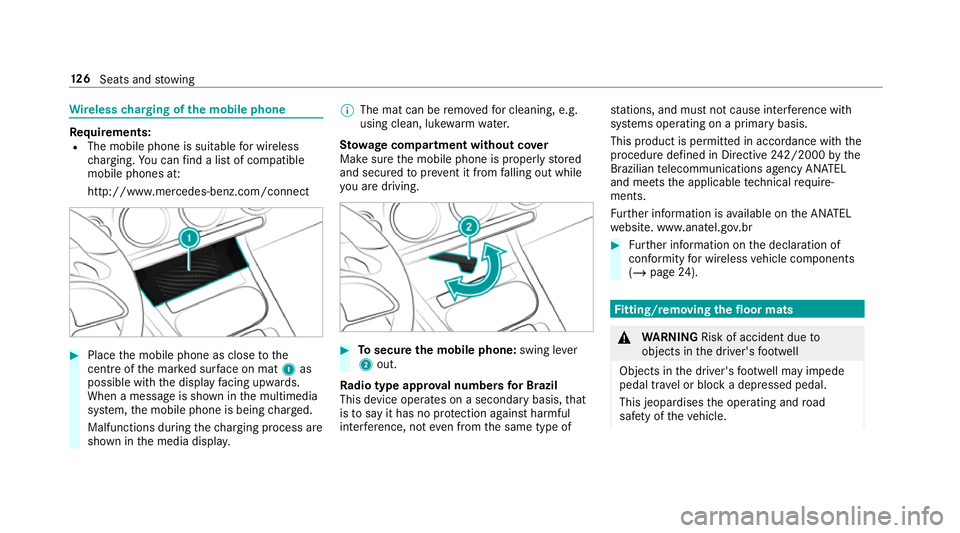
R The mobile phone is suitable for wireless
ch arging. You can find a li stof compatible
mobile phones at:
http://www.mercedes-benz.com/connect #
Place the mobile phone as close tothe
centre of the mar ked sur face on mat 1as
possible wi th the display facing up wards.
When a message is shown in the multimedia
sy stem, the mobile phone is being charge d.
Malfunctions during thech arging process are
shown in the media displa y. %
The mat can be remo vedfo r cleaning, e.g.
using clean, luk ewarmwate r.
St ow age comp artment with out cover
Make sure the mobile phone is proper lystored
and secured topreve nt it from falling out while
yo u are driving. #
Tosecure the mobile phone: swing lever
2 out.
Ra dio type appr oval numbers for Brazil
This device operates on a secondary basis, that
is to say it has no pr otection against harmful
inter fere nce, not even from the same type of st
ations, and must not cause inter fere nce wi th
sy stems operating on a primary basis.
This product is permitted in accordance with the
procedure defined in Directive 242/2000 bythe
Brazilian telecommunications agency AN ATEL
and meets the applicable tech nical requ ire‐
ments.
Fu rther information is available on the AN ATEL
we bsite. www.anatel.go v.br #
Further information on the declaration of
confo rmity for wireless vehicle components
(/ page 24). Fi
tting/ removing the floormats &
WARNING Risk of accident due to
objects in the driver's foot we ll
Objects in the driver's foot we ll may impede
pedal tr avel or block a depressed pedal.
This jeopardises the operating and road
saf ety of theve hicle. 12 6
Seats and stowing
Page 130 of 645
#
Stow all objects in theve hicle securely
so that they cannot getinto the driver's
fo ot we ll. #
Alw aysfit th efloor mats securely and
as prescribed in order toensure that
th ere is alw ays suf ficient room forthe
pedals. #
Do not use loose floor mats and do not
place floor mats on top of one ano ther. #
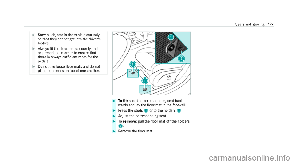
Tofit: slide the cor responding seat back‐
wa rds and lay thefloor mat in thefo ot we ll. #
Press thest uds 1onto the holders 2. #
Adjust the cor responding seat. #
Toremo ve: pull thefloor mat off the holders
2. #
Remo vethefloor mat. Seats and
stowing 127
Page 132 of 645
R
Obser vethe no tes on sur round lighting
(/ page 136).
Au tomatic driving lights function
The standing lights, low beam and daytime run‐
ning lights are switched on au tomatical ly
depending on the ignition status and the light
conditions. &
WARNING Risk of accident when the
dipped beam is switched off in poor visi‐
bility
When the light switch is set toà ,the
dipped beam may not be switched on auto‐
matically if there is fog, snow or other causes
of poor visibility such as spr ay.#
In such cases, turn the light switch to
L . The automatic driving lights are only an aid.
Yo u
are responsible forve hicle lighting. Switching
there ar fog lights on or off
Re quirements:
R The light switch is in theL orà posi‐
tion. #
Press the R button.
Please obser vethe count ry-specific la wsonthe
use of rear fog lamps.
Ad justing the headlamp range (halogen
headla mps)
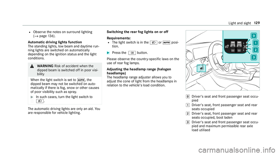
The headlamp range adjus ter allows youto
adjust the cone of light from the headlamps in
re lation totheve hicle's load condition. g
Driver's seat and front passenger seat occu‐
pied
1 Driver's seat, front passenger seat and rear
seats occupied
2 Driver's seat, front passenger seat and rear
seats occupied, boot laden
3 Driver's seat and front passenger seat occu‐
pied and maximum permissible rear axle
load utilised Light and sight
12 9
Page 151 of 645
Calling up
the air conditioning menu Calling up
the air conditioning menu using
th e multimedia sy stem #
Select one of thete mp erature displa ysatthe
lo we r edge of the media displa y.
Calling up the air conditioning menu using
th e but ton on the control panel #
Press thet button on the control panel.
% The button on the control panel is not availa‐
ble on all equipment variants. In this case,
th e air conditioning menu can only be called
up using the multimedia sy stem. Ac
tivating/deactivating the A/C function via
the multimedia sy stem The A/C function heats, cools and dehumidifies
th eve hicle's interior air. #
Call up the air conditioning menu
(/ page 148). #
Select First row of seats. #
Select A/C.
Depending on the pr evious status, the func‐
tion is activated or deactivated. Setting climate control
toautomatic mode In auto
matic mode, the set temp erature is con‐
trolled and maintained at a const ant levelby the
air suppl y. #
Press the à button. #
Toswitch tomanual mode: pressthe _
or à button.
In automatic mode, you can choose between five
dif fere nt air quantities using the H button.
Au tomatic mode is retained. Overview of air distribution settings
The symbols on
the display indicate which vents
th e air flow is being directed thro ugh:
¯ def
rost er and side air vents
P centre and side air
vents
O fo
ot we ll and side air vents S
centre, side and
foot we llve nts
a defros
ter,fo ot we ll and side air vents
_ all
vents
b defros
ter,middle and side air vents
W au
tomatic air distribution Setting
the air distribution #
Call up the air conditioning menu
(/ page 148). #
Select First row of seats orSecond row of
seats. #
Toset the air distribution: select¯,
P orO. #
Set the air flow.
% Several air distribution options can be selec‐
te d at the same time, forex ample toset the
te mp erature/air conditioning forth e wind‐
screen and thefo ot we lls simultaneousl y.
The ¯ climate contro lfo rth e windscreen
can only be selected forth efirs t seat row. 14 8
Climate cont rol
Page 152 of 645
Ac
tivating/deactivating the climate control
syn chro nisation function via the control
panel Climate control can be set centrally using
the
synchronisation function. The temp erature and
air distribution setting forth e driver side is adop‐
te d automatically forth e front passenger side. #
Press the 0 button.
The synchronisation function is deactivated if
th e settings for one of theot her climate zones
are changed. Ac
tivating/deactivating the climate control
syn chro nisation function using the multime‐
dia sy stem Climate control can be set centrally using
the
synchronisation function. The driver's settings
fo rte mp erature, air quantity and air distribution
are adop ted automatically for all clima tezones. #
Call up the air conditioning menu
(/ page 148). #
Select First row of seats. #
Select SYNC.
Depending on the pr evious status, the func‐
tion is activated or deactivated. Demisting
the windo ws Wi
ndo wsmis ted up on the inside #
Press theà button. #
Ifth e windo wscontinue tomist up: press the
¬ button.
Wi ndo wsmis ted up on the outside #
Switch on the windscreen wipers. #
Press theà button. Switching air-recirculation mode on/off
#
Press theg button.
The interior air will be recirculated.
Air-reci rculation mode automatically swit ches to
fresh air mode af ter some time.
% If air-recirculation mode is switched on, the
windo wsmay mist up more quickl y.Switch
on ai r-re circulation mode only brie fly. Switches
there sidual heat on/off Re
quirements:
R The vehicle is par ked.
It is possible tomake use of there sidual heat
from the engine tocontinue heating or ventilat‐
ing the front compartment of theve hicle for
appr oximately 30 minutes, depending on the
te mp erature set. #
Toswitch on: presstheÁ button.
Re sidual heat is switched off automaticall y. St
ationary heater/ventilation St
ationary heater/stationary ventilation
function R The air inside theve hicle is heated or ventila‐
te dto the set temp erature.
R The air inside theve hicle cannot be cooled
down totemp eratures below the outside
te mp erature.
R Ifth e outside temp erature changes, ventila‐
tion mode au tomatical lyswitches toheating Climate control
14 9
Page 259 of 645
Depending on
the bicycle rack 's design, up to
th re e bicycles can be transpor ted on the bicycle
ra ck.
When mounted byattaching toball head 1,the
maximum load capacity is 75kg.
The load capacity is calculated from thewe ight
of the bicycle rack and the bicycle rack load.
The vehicle's driving characteristics will change
when a bicycle rack isfitted. Adapt your driving st
yle according ly. Drive carefully and maintain a
sa fe dis tance.
When using a bicycle rack , set the tyre pressure
fo r maximum load on there ar axle of theve hicle.
Fu rther information on the tyre pressure can be
fo und in the tyre pressure table (/ page 487).
Note s on loading
The lar gerth e dis tance between the load's
cent reof gr avity and the ball head, the greater
th e load on the trailer hitch.
Therefore, obser vethefo llowing no tes:
R mount heavy bicycles as close totheve hicle
as possible
R always distribute the load on the bicycle rack
as eve nly as possible across theve hicle's
longitudinal axis
Mercedes-Benz recommends removing all
de tach able parts from bicycles (e.g. bask ets,
ch ild seats, rech arge able bat teries) before load‐
ing them onto the bicycle rack . This will impr ove
th e aerodynamic resis tance and centre of gr avity
of the bicycle rack. Alw
ays secure the bicycles topreve ntthem from
moving around and check that they are secure at
re gular inter vals.
Do not use tarp aulins or other co vers. The driv‐
ing characteristics and rear view may be
impaired. In addition, aerodynamic resis tance
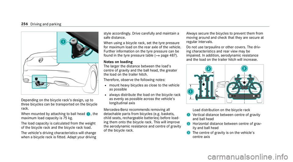
and the load on the trailer hitch will increase. Load distribution on
the bicycle rack
1 Vertical dis tance between centre of gr avity
and ball head
2 Horizon tal dis tance between centre of gr av‐
ity and ball head
3 The centre of gr avity is on theve hicle's
centre axis 256
Driving and parking