2019 MAZDA MODEL CX-5 SKYACTIV-D side mirror
[x] Cancel search: side mirrorPage 285 of 721

When there is a difference in the height between your driving lane and the adjacent
lane.
Directly after the BSM system becomes operable by changing the setting.
If the road width is extremely narrow, vehicles two lanes over may be detected. The
detection area of the radar sensors (rear) is set according to the road width of
expressways.
The BSM warning indicator light may turn on and the vehicle detection screen may be
displayed in the display in reaction to stationary objects (guardrails, tunnels, sidewalls,
and parked vehicles) on the road or the roadside.
Objects such as guardrails and concrete walls
running alongside the vehicle. Places where the width between guardrails or
walls on each side of the vehicle narrows.
The walls at the entrance and exits of tunnels
and turnouts.
A BSM warning indicator light may flash or the warning beep may be activated several
times when making a turn at a city intersection.
Turn off the BSM while pulling a trailer or wh
ile an accessory such as a bicycle carrier is
installed to the rear of the vehicle. Otherwise, the radar’s radio waves will be blocked
causing the system to not operate normally.
In the following cases, it may be difficult to view the illumination/flashing of the BSM
warning indicator lights equipped on the door mirrors.
Snow or ice is adhering to the door mirrors.
The front door glass is fogged or covered in snow, frost or dirt.
The radar sensors (rear) of the BSM may be regulated under the radio wave related laws
of the country where the vehicle is driven. The sensors in this system are approved for use
in the U.S.A. (including territories), Canada, and Mexico. If a vehicle with a BSM is
driven in a country other than the U.S.A., Canada, or Mexico, the system has to be turned
off by changing the setting on the center display.
The system switches to the Rear Cross Traffi c Alert (RCTA) function when the shift lever
(manual transaxle) or the selector lever (automatic transaxle) is shifted to the reverse (R)
position.
Refer to Rear Cross Traffic Alert (RCTA) on page 4-140.
When Driving
i-ACTIVSENSE
4-127
CX-5_8HH4-EA-19A_Edition1 2018-11-21 10:03:20
Page 298 of 721

Rear Cross Traffic Alert (RCTA)*
The RCTA system is designed to assist the driver in checking the area to the rear of the
vehicle on both sides while the vehicle is reversing by alerting the driver to the presence of
vehicles approaching th e rear of the vehicle.
The RCTA system detects vehicles approaching from the rear left and right sides of the
vehicle, and the rear of the vehicle while th e vehicle is being reversed out of a parking
space, and notifies the driver of possible danger using the Blind Spot Monitoring (BSM)
warning indicator lights and the warning buzzer.
Detection areas
Your vehicle
RCTA operation
1. The RCTA system operates when the shift le ver (manual transaxle) or the selector lever
(automatic transaxle) is shifted to the reverse (R) position.
2. If there is the possibility of a collision with an approaching vehicle, the Blind Spot
Monitoring (BSM) warning indi cator lights flashes and the warning beep is activated
simultaneously.
(With rear view monitor)
The RCTA warning indication in the rearview monitor also synchronizes with the Blind
Spot Monitoring (BSM) warning indicator light on the door mirrors.
When Driving
i-ACTIVSENSE
4-140*Some models.
CX-5_8HH4-EA-19A_Edition1 2018-11-21 10:03:20
Page 352 of 721

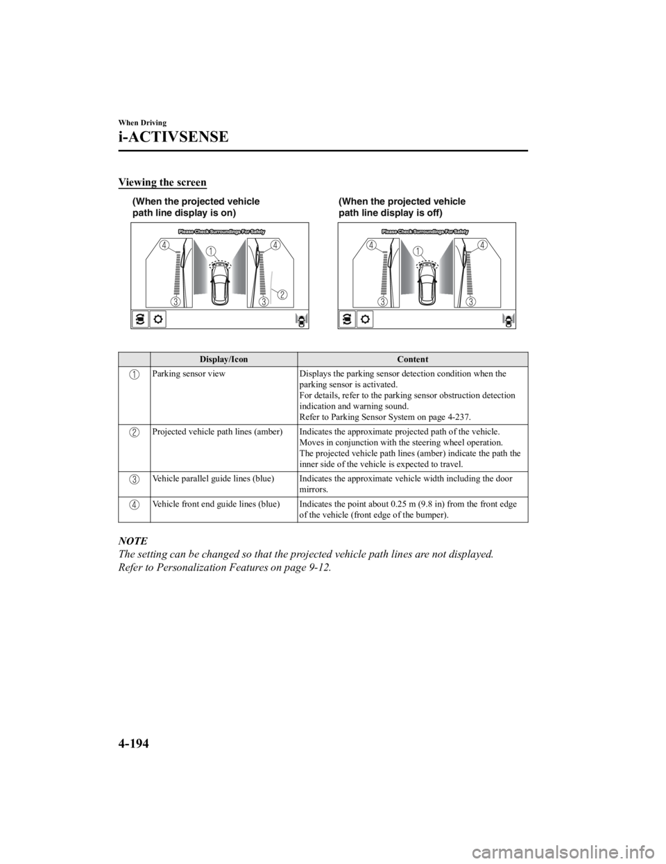
Viewing the screen
(When the projected vehicle
path line display is on)(When the projected vehicle
path line display is off)
Display/Icon
Content
Parking sensor viewDisplays the parking sensor detection condition when the
parking sensor is activated.
For details, refer to the parking sensor obstruction detection
indication and warning sound.
Refer to Parking Sensor System on page 4-237.
Projected vehicle path lines (amber) Indicates the approximate projected path of the vehicle. Moves in conjunction with the steering wheel operation.
The projected vehicle path lines (amber) indicate the path the
inner side of the vehicle is expected to travel.
Vehicle parallel guide lines (blue) Indicates th e approximate vehicle width including the door
mirrors.
Vehicle front end guide lines (blue) Indicates the point about 0.25 m (9.8 in) from the front edge of the vehicle (front edge of the bumper).
NOTE
The setting can be changed so that the projected vehicle path lines are not displayed.
Refer to Personalization Features on page 9-12.
When Driving
i-ACTIVSENSE
4-194
CX-5_8HH4-EA-19A_Edition1 2018-11-21 10:03:20
Page 353 of 721

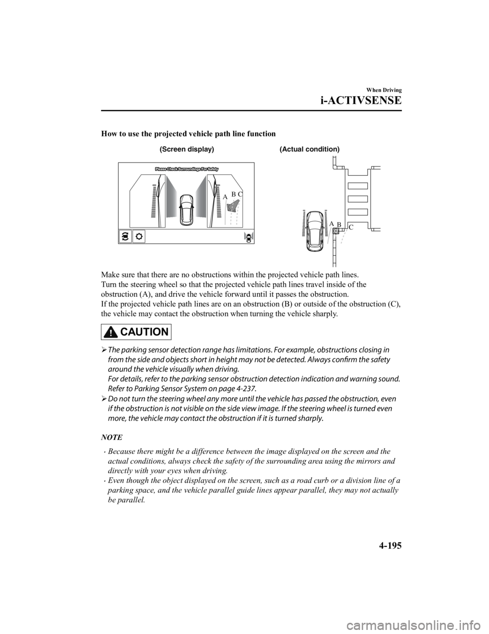
How to use the projected vehicle path line function
(Actual condition)
(Screen display)
AB
AB
C
C
Make sure that there are no obstructions within the projected vehicle path lines.
Turn the steering wheel so that the projected vehicle path lines travel inside of the
obstruction (A), and drive the vehicle forward until it passes the obstruction.
If the projected vehicle path lines are on an obs
truction (B) or outside of the obstruction (C),
the vehicle may contact the obstruction when turning the vehicle sharply.
CAUTION
The parking sensor detection range has limita tions. For example, obstructions closing in
from the side and objects short in height may not be detected. Always confirm the safety
around the vehicle vi sually when driving.
For details, refer to the parking sensor obstruction detection indication and warning sound.
Refer to Parking Sensor System on page 4-237.
Do not turn the steering wheel any more until the vehicle has passed the obstruction, even
if the obstruction is not visible on the side vi ew image. If the steering wheel is turned even
more, the vehicle may contact the obstruction if it is turned sharply.
NOTE
Because there might be a difference between the image displayed on the screen and the
actual conditions, always check the safety of the surrounding area using the mirrors and
directly with your eyes when driving.
Even though the object displayed on the screen, such as a road curb or a division line of a
parking space, and the vehicle parallel guide lines appear parallel, they may not actually
be parallel.
When Driving
i-ACTIVSENSE
4-195
CX-5_8HH4-EA-19A_Edition1 2018-11-21 10:03:20
Page 364 of 721

Do not disassemble or modify the Forward Sensing Camera (FSC).
Disassembly or modification of the Forward Sensing Camera (FSC) will cause a malfunction
or mistaken operation. Consequently, each sy stem may not operate normally which could
lead to an unexpected accident.
Heed the following cautions to assure the correct operation of the Forward Sensing Camera
(FSC).
Be careful not to scratch the Forward Sensing Camera (FSC) lens or allow it to get dirty.
Do not remove the Forward Sensing Camera (FSC) cover.
Do not place objects on the dashboard which reflect light.
Always keep the windshield glass around the camera clean by removing dirt or fogging.
Use the windshield defroster to remove fogging on the windshield.
Consult an Authorized Mazda Dealer regardi ng cleaning the interior side of the
windshield around the Forw ard Sensing Camera (FSC).
Consult an Authorized Mazda Dealer before performing repairs around the Forward
Sensing Camera (FSC).
The Forward Sensing Camera (FSC) is installe d to the windshield. Consult an Authorized
Mazda Dealer for windshield repair and replacement.
When cleaning the wind shield, do not allow glass cleaners or similar cleaning fluids to
get on the Forward Sensing Camera (FSC) le ns. In addition, do not touch the Forward
Sensing Camera (FSC) lens.
When performing repairs around the rearv iew mirror, consult an Authorized Mazda
Dealer.
Consult an Authorized Mazda Dealer regarding cleaning of the camera lens.
Do not hit or apply strong force to the Forward Sensing Camera (FSC) or the area around
it. If the Forward Sensing Camera (FSC) is severely hit or if there are cracks or damage
caused by flying gravel or debris in the area around it, stop using the following systems
and consult an Authorized Mazda Dealer.
High Beam Control System (HBC)
Lane-keep Assist System (LAS) & Lane Departure Warning System (LDWS)
Traffic Sign Recognition System (TSR)
Advanced Smart City Brak e Support (Advanced SCBS)
Smart City Brake Support (SCBS)
Mazda Radar Cruise Control with Stop & Go function (MRCC with Stop & Go function)
Smart Brake Support (SBS)
The direction in which the Forward Sensing Camera (FSC) is pointed has been
finely
adjusted. Do not change the installation posi tion of the Forward Sensing Camera (FSC) or
remove it. Otherwise, it could result in damage or malfunction.
Always use tires for all wheels that are of the specified size, and the same manufacturer,
brand, and tread pattern. In addition, do no t use tires with significantly different wear
patterns on the same vehicle as the system may not operate normally.
When Driving
i-ACTIVSENSE
4-206
CX-5_8HH4-EA-19A_Edition1 2018-11-21 10:03:20
Page 498 of 721

Sunvisors
When you need a sunvisor, lower it for use
in front or swing it to the side.
Sunvisor
▼ Side Extension Sunvisors*
The visor extender extends the sunvisor's
range of sun shading.
To use, pull it out.
CAUTION
When moving the sunvisor, retract the visor
extender to its original position. Otherwise,
the visor extender could hit the rearview
mirror.
▼ Va n i t y M i r r o r s
To use the vanity
mirror, lower the
sunvisor.
If your vehicle is equipped with a vanity
mirror light, it will illuminate when you
open the cover.
To prevent the battery from being
discharged, the vanity mirror will only
illuminate in the tilt range shown in the
figure.
offoff
on
Interior Features
Interior Equipment
5-94*Some models.
CX-5_8HH4-EA-19A_Edition1 2018-11-21 10:03:20
Page 563 of 721

Light Bulbs
Side turn signal
lights
Vanity mirror
lights
Type A
Type B
Overhead lights/Front map
lights
Side turn
signal lights
Vanity mirror lights
Overhead lights/Front map
lights Front turn signal lights/Parking
lights Rear turn signal lights
License plate lights Luggage compartment
light
Reverse lights
Brake lights/Taillights
Brake lights
High-mount
brake light Rear map lights
Rear turn signal lights
License plate lights
Luggage compartment
lightReverse lights
Brake lights/Taillights/Rear
side-marker lights High-mount brake light
Rear map lights
Fog lights
Headlights (High/Low beam)
/Daytime running lights
Front side-marker lights
Rear side-marker lights
Daytime running lights/Parking
lights
Front turn signal
lights/Parking lights Fog lights Front side-marker lights
Some models.
Headlights (High/Low beam)
/Daytime running lights
Ambient lights
Ambient lights
Maintenance and Care
Owner Maintenance
6-51
CX-5_8HH4-EA-19A_Edition1
2018-11-21 10:03:20
Page 566 of 721

3. Turn the screws counterclockwise andremove them.
4. Pull the unit rearward to remove it.
5. Turn the socket and bulb assemblycounterclockwise and remove it.
6. Disconnect the bulb from the socket.
Rear turn signal lights
Brake lights/Taillights/Rear
side-marker lights
7. Install the new bulb in the reverseorder of the removal procedure.
▼Replacing Interior Light Bulbs
The interior lights have either LEDs or
normal bulbs.
LED type
Overhead lights/
Front map lights
Rear map lights
Vanity mirror lights*
Luggage compartment light
Ambient lights*
The LED bulb cannot be replaced as a
single unit because it is an integrated unit.
The LED bulb has to be replaced with the
unit. We recommend an Authorized
Mazda Dealer when the replacement is
necessary.
Bulb type
Overhead light/Front map lights, Rear
map lights, Vanity mirror lights
*
1. Wrap a flathead screwdriver with a
soft cloth to prevent damage to the
lens, and then remove the lens by
carefully prying on the edge of the lens
with a flathead screwdriver.
Maintenance and Care
Owner Maintenance
6-54*Some models.
CX-5_8HH4-EA-19A_Edition1 2018-11-21 10:03:20