2019 MASERATI QUATTROPORTE automatic transmission
[x] Cancel search: automatic transmissionPage 257 of 396
CAUTION!
• Under normal conditions, all red
warning lights on the instrument
cluster display should be off. When
they come on, this indicates a
malfunction. Refer to “Instrument
Cluster” in section “Dashboard
Instruments and Controls”.
• Continuing to drive when a red
warning light is on could cause
serious damage to the vehicle and
affect its performance.
Onboard Diagnostic System Your vehicle is equipped with a
sophisticated onboard diagnostic
system. This system monitors the
performance of the emissions, engine,
and automatic transmission control
systems. When these systems are
operating properly, your vehicle will
provide excellent performance and
fuel economy, as well as engine
emissions well within current local
regulations of various countries.
If any of these systems require service,
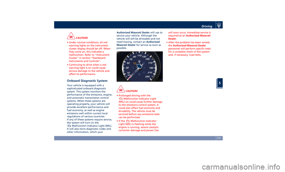
the system will turn on the
Malfunction Indicator Light (MIL).
It will also store diagnostic codes and
other information, which your Authorized Maserati Dealer will use to
service your vehicle. Although the
vehicle will still be driveable and not
need towing, contact an Authorized
Maserati Dealer for service as soon as
possible.
CAUTION!
• Prolonged driving with the
Malfunction Indicator Light
(MIL) on could cause further damage
to the emissions control system. It
could also affect fuel economy and
drivability. The vehicle must be
serviced before any emissions tests
can be performed.
•Ifthe
Malfunction Indicator
Light (MIL) is flashing while the
engine is running, severe catalytic
converter damage and power loss will soon occur. Immediate service is
required at an Authorized Maserati
Dealer .
• After the problem has been solved,
the Authorized Maserati Dealer
personnel will perform specific tests
for a complete check of the system
and, if necessary, road tests.Driving
5
253
Page 264 of 396

NOTE:
Any change made to tire dimensions
affects performance of Adaptive Cruise
Control and Front Collision Warning
(FCW), if equipped.
The ACC is not activated in the
following conditions:
• When braking.
• When parking brake is activated.
• When automatic transmission is in P
(Park), R (Reverse) or N (Neutral).
• When vehicle speed is out of preset
speed range
• When brakes are overheated.
• When driver door is open.
• When the driver’s seat belt is
unbuckled.
• When the road is particularly steep
(both uphill and downhill) at low
speed.
• When drive mode
(ESC OFF) is
selected.
• When the door is opened at low
speed.
• When there has been an ESC event in
the last 5 seconds, or is still active.
• When there is an object too close in
front of the vehicle.
It is possible that more than one
system is active at the same time such as ACC and ABSA just to mention
some.
While activation of ACC and CC at the
same time is impossible.
Speed Range of Use Speed mph (km/h)
Minimum 0 (0)
Engaged/activated 18 (30)
Maximum 130 (210)
Activation/Deactivation NOTE:
Pictures show status of ACC and LKA
systems.
Press and release
ON/OFF button to
activate the ACC. The display will show
the
white symbol with below 3
dashes will illuminate indicating that
system is ready to be set.
If a vehicle is detected as being too
close, the display will show a message
for 5 seconds and trigger a signal to
warn the driver that current conditions
do not allow enabling of the ACC. At
any rate, system will remain in the
ready status. Driver Assist Page
Non-Driver Assist PageDriving
5
260
Page 328 of 396
Jump-Start Procedure WARNING!
• Stay clear of the radiator cooling fan
whenever the engine hood is raised.
It can start anytime the ignition
switch is on. You could be injured by
the moving fan blades.
• Remove any metal jewelry such as
watch bands or bracelets that might
make an inadvertent electrical
contact. You could be seriously
injured.
• Do not allow the vehicles involved in
the jumpstarting operation to touch
each other as this could establish a
ground connection and cause
personal injury.
• Turn off the heater, radio, and all
unnecessary
electrical accessories.
•
Set the parking brake, shift the
automatic transmission into P (Park)
and turn the ignition to OFF .
• If using another vehicle to jumpstart
the battery, park the vehicle within
the jumper cables reach and set the
parking brake and make sure the
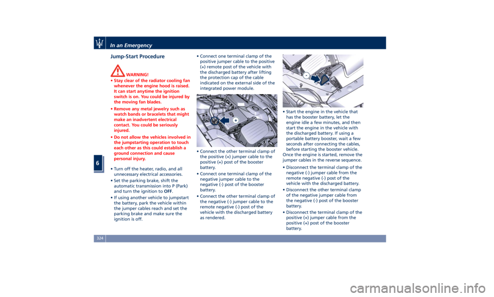
ignition is off. • Connect one terminal clamp of the
positive jumper cable to the positive
(+) remote post of the vehicle with
the discharged battery after lifting
the protection cap of the cable
indicated on the external side of the
integrated power module.
• Connect the other terminal clamp of
the positive (+) jumper cable to the
positive (+) post of the booster
battery.
• Connect one terminal clamp of the
negative jumper cable to the
negative (-) post of the booster
battery.
• Connect the other terminal clamp of
the negative (-) jumper cable to the
remote negative (-) post of the
vehicle with the discharged battery
as rendered. • Start the engine in the vehicle that
has the booster battery, let the
engine idle a few minutes, and then
start the engine in the vehicle with
the discharged battery. If using a
portable battery booster, wait a few
seconds after connecting the cables,
before starting the booster vehicle.
Once the engine is started, remove the
jumper cables in the reverse sequence.
• Disconnect the terminal clamp of the
negative (-) jumper cable from the
remote negative (-) post of the
vehicle with the discharged battery.
• Disconnect the other terminal clamp
of the negative jumper cable from
the negative (-) post of the booster
battery.
• Disconnect the terminal clamp of the
positive (+) jumper cable from the
positive (+) post of the booster
battery.In an Emergency
6
324
Page 336 of 396

• short, repeated journeys (less than
4–5 mi/7-8 km) at sub-zero outside
temperatures;
• engine often idling or driving long
distances at low speeds or long
periods of idleness;
you should perform the following
inspections more frequently than
recommended on the “Scheduled
Service Plan”:
• check front disc brake pad conditions
and wear;
• check cleanliness of hood and trunk
locks, cleanliness and lubrication of
linkage;
• visually inspect conditions of: engine,
transmission, pipes and hoses
(exhaust - fuel system - brakes) and
rubber elements (boots - sleeves -
bushes - etc.);
• check battery charge;
• visually inspect condition of the
accessory drive belts;
• check and, if necessary, change
engine oil and replace oil filter;
• check and, if necessary, replace
pollen filter of the A/C system;
• check and, if necessary, replace air
cleaner filter. CAUTION!
All maintenance operations for the
vehicle must be carried out by an
Authorized Maserati Dealer . For
routine and minor maintenance
operations which you can carry out
yourself, make sure that you have the
necessary experience and always use
suitable equipment, original Maserati
spare parts and the prescribed fluids.
Shall this not be the case, do not carry
any operation on your own and
contact an Authorized Maserati
Dealer .
On Board Diagnostic System Your vehicle is equipped with a
sophisticated on board diagnostic
system called OBD II. This system
monitors the performance of the
emissions, engine, and automatic
transmission control systems. When
these systems are operating properly,
your vehicle will provide excellent
performance and fuel economy, as
well as engine emissions suited to
current government regulations.
If any of these systems require service,
the OBD II system will turn on the
Malfunction Indicator Light
on the
instrument cluster display (refer to “Instrument Cluster” in section
“Dashboard Instruments and
Controls”). The system stores as well
diagnostic codes and other
information to assist your service
technician by performing repairs.
Although the vehicle will be driveable
and will not need towing, contact an
Authorized Maserati Dealer for service
as soon as possible.
CAUTION!
• Prolonged driving with the MIL
on could cause further damage to
the emissions control system. It could
also affect fuel economy and
driveability. The vehicle must be
serviced before any emissions tests
can be performed.
• If the MIL
is flashing while the
engine is running, severe catalytic
converter damage and power loss
will soon occur. Immediate service at
an Authorized Maserati Dealer is
required.
Emissions Inspection and
Maintenance Programs In some localities, it may be a legal
requirement to pass an inspection of
your vehicle's emissions control system.Maintenance and Care
7
332
Page 345 of 396
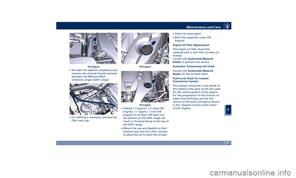
• Re-insert the dipstick completely and
remove: the oil level should maintain
between the MIN and MAX
reference ranges (SAFE range).
• If a refilling is necessary, unscrew the
filler neck cap. • Adding 1.5 Quarts / 1.4 Litres (V8
Engine), 1.1 Quarts / 1 Litre (V6
Engine) of oil when the level is at
the bottom of the SAFE range will
result in the level being at the top of
the SAFE range.
• Return the cap and dipstick to their
position and wait for a few minutes
to allow the oil to reach the oil pan. • Check the level again.
• Refit the inspection cover (V8
Engine).
Engine Oil Filter Replacement
The engine oil filter should be
replaced with a new filter at every oil
change.
Contact the Authorized Maserati
Dealer to perform this service.
Automatic Transmission Oil Check
Contact the Authorized Maserati
Dealer for the oil level check.
Fluid Level Check for Coolant
Transmission System
The coolant contained in the bottle of
this system is the same as the one used
for the cooling system of the engine.
For the preparation of the mixture of
water and antifreeze and for the
control of the level, proceed as shown
in the “Engine Coolant Level Check”
of this chapter.V6 Engine V8 Engine
V6 Engine Maintenance and Care
7
341
Page 375 of 396
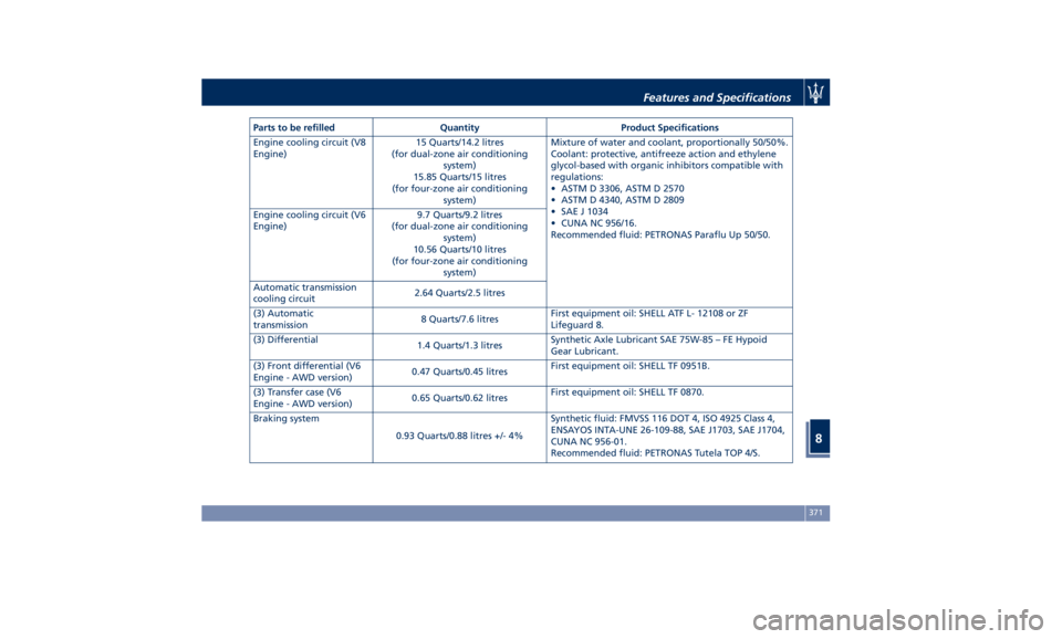
Parts to be refilled Quantity Product Specifications
Engine cooling circuit (V8
Engine) 15 Quarts/14.2 litres
(for dual-zone air conditioning
system)
15.85 Quarts/15 litres
(for four-zone air conditioning
system) Mixture of water and coolant, proportionally 50/50%.
Coolant: protective, antifreeze action and ethylene
glycol-based with organic inhibitors compatible with
regulations:
• ASTM D 3306, ASTM D 2570
• ASTM D 4340, ASTM D 2809
• SAE J 1034
• CUNA NC 956/16.
Recommended fluid: PETRONAS Paraflu Up 50/50.Engine cooling circuit (V6
Engine) 9.7 Quarts/9.2 litres
(for dual-zone air conditioning
system)
10.56 Quarts/10 litres
(for four-zone air conditioning
system)
Automatic transmission
cooling circuit 2.64 Quarts/2.5 litres
(3) Automatic
transmission 8 Quarts/7.6 litres First equipment oil: SHELL ATF L- 12108 or ZF
Lifeguard 8.
(3) Differential
1.4 Quarts/1.3 litres Synthetic Axle Lubricant SAE 75W-85 – FE Hypoid
Gear Lubricant.
(3) Front differential (V6
Engine - AWD version) 0.47 Quarts/0.45 litres First equipment oil: SHELL TF 0951B.
(3) Transfer case (V6
Engine - AWD version) 0.65 Quarts/0.62 litres First equipment oil: SHELL TF 0870.
Braking system
0.93 Quarts/0.88 litres +/- 4% Synthetic fluid: FMVSS 116 DOT 4, ISO 4925 Class 4,
ENSAYOS INTA-UNE 26-109-88, SAE J1703, SAE J1704,
CUNA NC 956-01.
Recommended fluid: PETRONAS Tutela TOP 4/S.Features and Specifications
8
371
Page 380 of 396
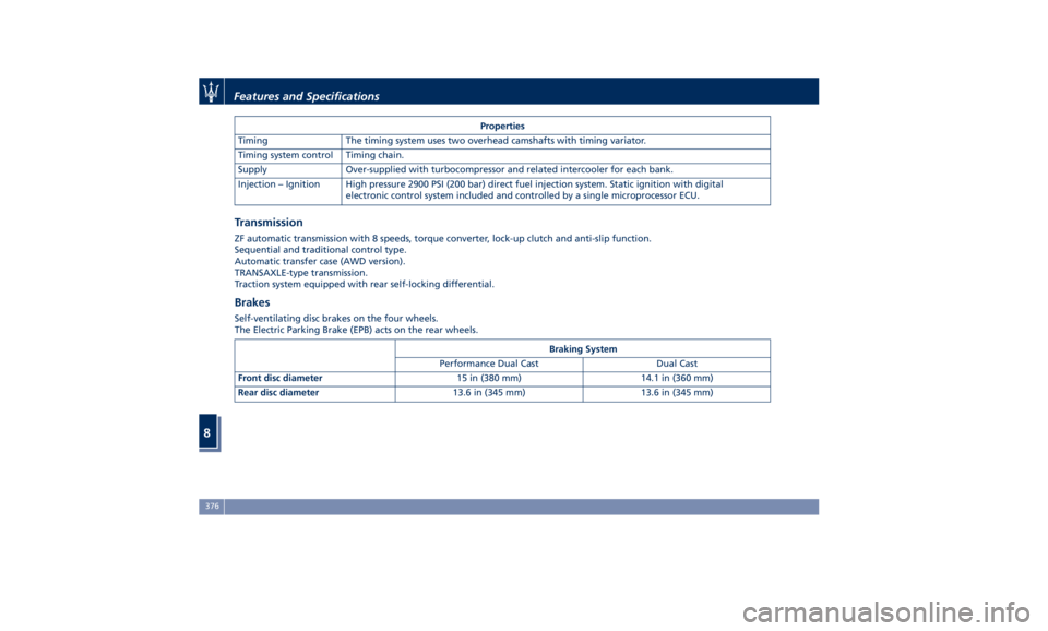
Properties
Timing The timing system uses two overhead camshafts with timing variator.
Timing system control Timing chain.
Supply Over-supplied with turbocompressor and related intercooler for each bank.
Injection – Ignition High pressure 2900 PSI (200 bar) direct fuel injection system. Static ignition with digital
electronic control system included and controlled by a single microprocessor ECU.
Transmission ZF automatic transmission with 8 speeds, torque converter, lock-up clutch and anti-slip function.
Sequential and traditional control type.
Automatic transfer case (AWD version).
TRANSAXLE-type transmission.
Traction system equipped with rear self-locking differential.
Brakes Self-ventilating disc brakes on the four wheels.
The Electric Parking Brake (EPB) acts on the rear wheels.
Braking System
Performance Dual Cast Dual Cast
Front disc diameter 15 in (380 mm) 14.1 in (360 mm)
Rear disc diameter 13.6 in (345 mm) 13.6 in (345 mm)Features and Specifications
8
376
Page 388 of 396

Abbreviations .................9
Accessories
Aftermarket Parts and Accessories
Statement .................13
Active Blind Spot Assist - ABSA . . . .281
Adaptive Cruise Control (ACC) . . . .257
Activation/Deactivation ...... .260
Display Warnings and
Maintenance ............. .265
Precautions while Driving with
ACC ................... .266
Setting the Following Distance . .262
Setting the Speed .......... .261
Airbag.....................66
Advanced Front Air Bag
Properties .................67
Air Bag Deployment Result .....72
Air Bag Deployment Sensors and
Controls ..................15
Air Bag System Components .....67
Front Air Bag Inflator Units .....71
Passenger Air bag Labels .......20
Supplemental Restraint System
(SRS) .....................66
Supplemental Seat-mounted Side
Air Bags (SAB) ..............69
Supplemental Side Air Bag Inflatable
Curtain (SABIC) ..............69
Transport of persons with
disability ..................73
Air Conditioning (A/C) System . . . .203
A/C Distribution ........... .147 Air Conditioning System (A/C System)
Four-zone Controls ......... .209
Alarm, Vehicle Security ..........28
ALR (Automatic Locking Retractor) . .64
Anti-Lock Braking System (ABS) and
Electronic Brake-force Distribution
(EBD) ................... .249
Assistance ...................11
Assistance, if you need ..........11
ATC (Automatic Temperature
Control) ................. .209
Audio Controls .............. .183
Audio Controls on Central
Console ................. .183
Steering Wheel Audio Controls . .183
Audio, setting .............. .197
Audio System ............... .184
Automatic Transmission
Manual Release of Transmission .325
AUX, USB and SD Memory Card
Ports .................... .134
AWD
All-Wheel Drive, drive mode . . . .233
BAS (Brake Assist System) ...... .250
Battery ................... .344
Battery Recharge .......... .347
Battery Remote Posts Position. . .323
Maintaining Battery Charge . . . .366
To Disconnect the Battery .... .344
To Reconnect the Battery
..... .345
Blind
Spot Alert .............
.276
BSA System .............. .276 RCP - Rear Cross Path ........ .279
Bluetooth, Customer settings .... .198
Bodywork Maintenance and Care . .360
Pre-Short Drop Function ..... .362
Protection from Atmospheric
Agents ................. .360
Useful Advice to Keep the Bodywork
in Good Condition ......... .360
Brakes
Brake and Stability Control System
(ESC) ................... .248
Brake Overheating ......... .252
Brake System ............. .248
Manual Release of Parking
Brake .................. .321
Parking Brake ............. .243
Using the Brakes ........... .251
Capacity/Refillings ........... .370
Cargo Area ................ .139
Loading with Rear Seatbacks Folded
Down .................. .140
Vehicle Load Carrying Capacity . .139
Child Restraint Systems ..........74
Children too large for Booster
Seats .....................75
Infants and Child Restraints .....74
Installing Child Restraint Systems
using the Vehicle Seat Belt equipped
with ALR ..................76
Lower Anchors and Tether for
Children (LATCH) ............77Index
9 384