Page 293 of 396

• Press the HAS enable button on
the steering wheel.
• Begin steering manually.
• Press brake pedal.
• Turn off ACC.
• Unbuckle the driver’s seat belt.
• Press ACC Gap button for two
seconds to enable CC system.
• Shift out of the (D) Drive gear.
• Enter an Autonomous Emergency
Braking (AEB) event (See chapter
"Forward Collision Warning - FCW"
in this section).
• Turn signal activated.
System Cancellation The HAS system will cancel (without
driver intervention) if either of the
following actions occur:
• Curve that is too tight.
• When leaving the grip of the hands
on the steering wheel.
• Vehicle exits the highway or limited
access freeway.
• Lane line markers aren’t detected by
the forward facing camera.
• Any ADAS system faults.
• ACC cancellation.
• Vehicle speed exceeds the maximum
limit. • Lateral accelerations exceeds the
limits.
NOTE:
• When HAS cancels, the
symbol
will turn red then grey.
• The presence of the hands on the
steering wheel is detected by a logic
combination of a capacitive sensor
installed in the steering wheel and
the measured applied torque at the
steering column. This leads to a
more robust hands detection.
System Limitations HAS is unable to guide the vehicle
when the following conditions occur.
• Lane markings are not clear or
visibility is poor (i.e. heavy rain,
snow, fog, etc.).
• Obstructed, covered or damaged
forward-facing camera or sensor.
• When driving on hills or sharp
curves.
• When approaching toll booths.
• When the highway entrance or exit
is wider than 20 ft (6 meters).
• Bright light (ex. direct sunlight or
glare) facing the forward camera. WARNING!
Many unforeseen conditions can occur
that can affect the performance of
Highway Assist (HAS). Always keep
this in mind and drive attentively. It is
the drivers responsibility to keep
control of the vehicle at all times.
Radar Device - Regulatory
Information The “Regulatory Information” for all
the radio frequency and radar devices
can be consulted by accessing the
“Services” section on the website
www.maserati.com.Driving
5
289
Page 323 of 396
specific fitting wrench provided with
the “Wheel Security Stud Bolt Kit”,
available in the “Genuine
Accessories” range.
• Fit the compact spare wheel with the
valve stem facing outward, securing
it with the five bolts previously
removed. • Turn the lever of the jack to lower
the vehicle and remove the jack.
• Fully tighten the bolts, alternately
tightening diametrically opposite.
WARNING!
• FOR ALUMINIUM SPARE WHEEL
Observe the tightening torque for
the bolts securing the spare wheel
(72 ± 7 lbf·ft/ 98 ± 10 Nm).
• FOR STEEL SPARE WHEEL
Observe the tightening torque for
the bolts securing the spare wheel
(63 ± 7 lbf·ft/ 86 ± 10 Nm).
• To avoid the risk of forcing the
vehicle off the jack, do not tighten
the wheel bolts fully until the
vehicle has been lowered. Failure to
follow this warning may result in
personal injury.In an Emergency
6
319
Page 324 of 396

WARNING!
• The spare wheel is narrower than
standard wheels and must only be
used to travel the distance required
to reach a service station, where the
punctured tire can be repaired or
replaced.
• Do not exceed a maximum speed of
50 mph (80 km/h) when using the
compact spare wheel; when this
limit is exceeded, the stability, road
holding and braking of the vehicle
will be compromised. Avoid
accelerating to full speed, heavy
braking and fast cornering.
• The compact spare wheel must be
inflated to the recommended tire
pressure (see “Tire Inflation
Pressure” in section “Features and
Specifications”). • For safety reasons, it is absolutely
forbidden to drive with more than
one compact spare wheel fitted on
the vehicle.
• Snow chains cannot be fitted on the
compact spare wheel.
• The spare wheel can travel a
maximum of 1,800 mi (3.000 km).
To Refit the Standard Wheel with
Repair
ed or
Replaced Tire
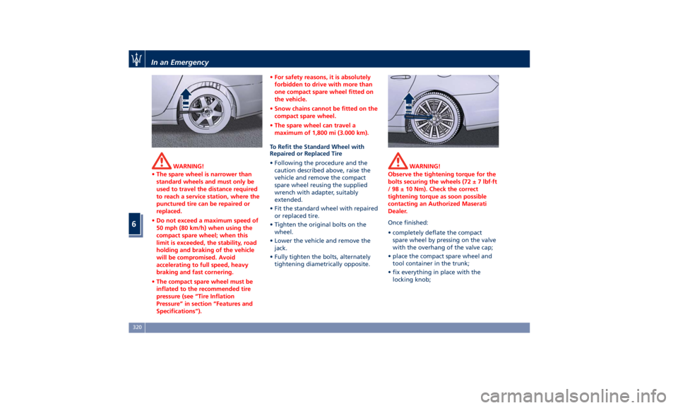
• Following the procedure and the
caution described above, raise the
vehicle and remove the compact
spare wheel reusing the supplied
wrench with adapter, suitably
extended.
• Fit the standard wheel with repaired
or replaced tire.
• Tighten the original bolts on the
wheel.
• Lower the vehicle and remove the
jack.
• Fully tighten the bolts, alternately
tightening diametrically opposite. WARNING!
Observe the tightening torque for the
bolts securing the wheels (72 ± 7 lbf·ft
/ 98 ± 10 Nm). Check the correct
tightening torque as soon possible
contacting an Authorized Maserati
Dealer.
Once finished:
•
completely deflate
the compact
spare wheel by pressing on the valve
with the overhang of the valve cap;
• place the compact spare wheel and
tool container in the trunk;
• fix everything in place with the
locking knob;In an Emergency
6
320
Page 330 of 396

(Continued)
ignition switch is in the OFF position. If
this is not observed, when the ESC is
active, the ECU will store a
malfunction and the relative warning
light
will illuminate on the
instrument cluster display. This
requires the intervention of an
Authorized Maserati Dealer to reset
the system.
Towing an AWD Vehicle
WARNING!
Single axle towing or use of a tow
dolly is not allowed since it will
severely damage components of an
AWD vehicle.
WARNING!
Use of a tow dolly on front wheels is
strictly forbidden since front wheels
may still receive a residual amount of
torque and disengage the vehicle from
the tow dolly and affect safety of
both rescuers and other road users. Use the Tow Hook of the Tool
Kit CAUTION!
The tow hook should only be used for
towing the car on flat roads. Do not
use the tow hook to remove the car
that is stuck on off road stretches.
The tow hook is also used to tow the
vehicle
on the
platform of a tow truck.
The tow hook is contained in the tool
kit (see “Tool Kit” in this section) and
must be screwed in its seat accessible
behind the front grille, right-hand
side, after removing the protective
cap.
• Carefully clean the threaded seat
before screwing the hook.
• Screw the tow hook into its seat for
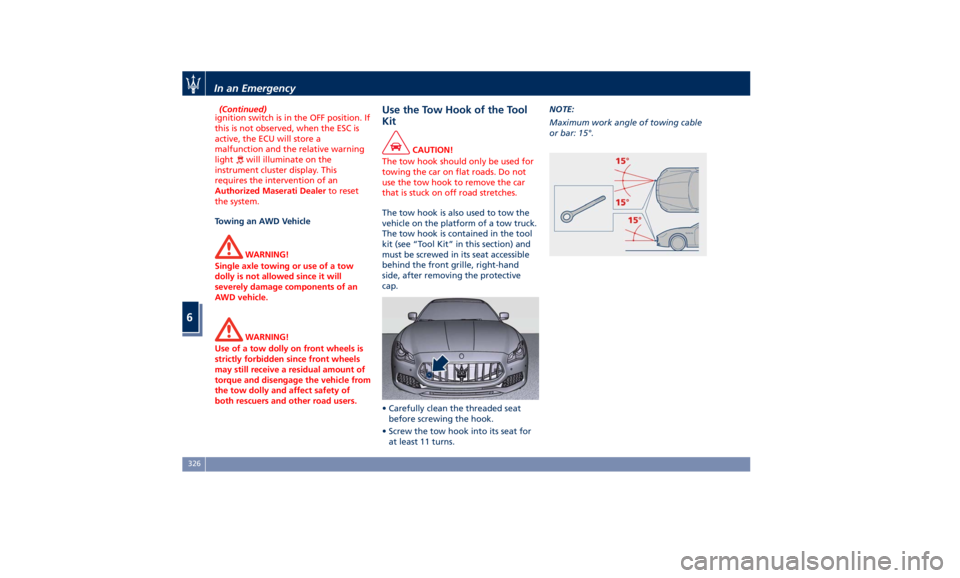
at least 11 turns. NOTE:
Maximum work angle of towing cable
or bar: 15°.
In an Emergency
6
326
Page 379 of 396
Technical Data NOTE:
The technical data, values and specifications in this Owner’s Manual are provided as guidance only. The vehicle specific
data can vary from the information provided, for example, as a result of optional or special equipment ordered with the
vehicle, vehicle loads, and country specific measurement methods.
Engine Data Quattroporte GTS Quattroporte S - Quattroporte
SQ4 (AWD version)
Cylinder number and position 8 - 90° V 6 - 60° V
Number of valves per cylinder 4 4
Bore x stroke 86.5 x 80.8 mm 86.5 x 84.5 mm
Total displacement 3,799 cm 3
2,979 cm 3
Compression ratio 9.5 : 1 9.7 : 1
Maximum power output (EC) 390 kW – 523 HP 316 kW – 424 HP
- corresponding RPM 6,700 RPM 5,750 RPM
Peak torque (EC) 480 ft-lb (650 N-m) 428 ft-lb (580 N-m)
- corresponding RPM 2,000 – 4,000 RPM 1,750 – 4,500 RPM
Overboost torque (EC) 524 ft-lb (710 N-m) 428 ft-lb (580 N-m)
- corresponding RPM 2,000 – 4,000 RPM 1,750 – 4,500 RPMFeatures and Specifications
8
375
Page 380 of 396
Properties
Timing The timing system uses two overhead camshafts with timing variator.
Timing system control Timing chain.
Supply Over-supplied with turbocompressor and related intercooler for each bank.
Injection – Ignition High pressure 2900 PSI (200 bar) direct fuel injection system. Static ignition with digital
electronic control system included and controlled by a single microprocessor ECU.
Transmission ZF automatic transmission with 8 speeds, torque converter, lock-up clutch and anti-slip function.
Sequential and traditional control type.
Automatic transfer case (AWD version).
TRANSAXLE-type transmission.
Traction system equipped with rear self-locking differential.
Brakes Self-ventilating disc brakes on the four wheels.
The Electric Parking Brake (EPB) acts on the rear wheels.
Braking System
Performance Dual Cast Dual Cast
Front disc diameter 15 in (380 mm) 14.1 in (360 mm)
Rear disc diameter 13.6 in (345 mm) 13.6 in (345 mm)Features and Specifications
8
376
Page:
< prev 1-8 9-16 17-24