2019 MASERATI LEVANTE stop start
[x] Cancel search: stop startPage 280 of 436

exits from this strategy when the
accelerator pedal is completely
unstuck.
Hill Start Assist (HSA) The HSA system is designed to assist
the driver when starting a vehicle
uphill. HSA will maintain the level of
brake pressure applied for a short
period of time also after releasing the
brake pedal.
If the driver does not apply the
throttle during this short period of
time, the system will release brake
pressure and the vehicle will start
sloping down. The system will release
brake pressure proportionally to the
amount of throttle/torque applied as
the vehicle starts to move in the
chosen direction.
HSA Activation Criteria
The following criteria must be met in
order for HSA to activate:
• vehicle is stationary;
• gear selection matches vehicle uphill
direction (i.e., vehicle facing uphill is
in forward gear; vehicle backing
uphill is in reverse gear).
HSA will work in R (Reverse) and all
forward gears when the activation
criteria have been met. The system will not activate if the
transmission is placed in N (Neutral) or
P (Park).
Roll-Over Mitigation (ROM) This system anticipates the potential
for wheel lift by monitoring the
driver's steering wheel input and the
speed of the vehicle. When ROM
determines that the rate of change of
the steering wheel angle and vehicle's
speed are sufficient to potentially
cause wheel lift, it then applies the
appropriate brake and may also
reduce engine power to lessen the
chance that wheel lift will occur.
ROM will only intervene during very
severe or evasive driving maneuvers.
ROM can only reduce the chance of
wheel lift occurring during severe or
evasive driving maneuvers. It cannot
prevent wheel lift due to other factors,
such as road and off-road conditions,
leaving the roadway, or striking
objects or other vehicles.
WARNING!
Many factors, such as vehicle loading,
road and off-road conditions, and
driving conditions, influence the
chance that wheel lift or rollover may occur. ROM cannot prevent all wheel
lift or roll-overs, especially those that
involve leaving the roadway or
striking objects or other vehicles. The
capabilities of a ROM-equipped
vehicle must never be exploited in a
reckless or dangerous manner, which
could jeopardize the user’s safety or
the safety of others.
Trailer Sway Mitigation (TSM) TSM uses sensors in the vehicle to
recognize an excessively swaying
trailer and will take the appropriate
actions to attempt to stop the sway.
The system may reduce engine power
and apply the brake of the
appropriate wheel(s) to counteract the
sway of the trailer. TSM will become
active automatically once an
excessively swaying trailer is
recognized.
TSM cannot stop all trailers from
swaying. Always use caution when
towing a trailer and follow the trailer
tongue weight recommendations.
Refer to “Trailer Towing” in this
section for further information. When
TSM is functioning, the “ESC
Activation/Malfunction Indicator
Light” will flash (see “Instrument
Cluster” in section “DashboardDriving
5
276
Page 297 of 436

NOTE:
The displayed warning is a warning
for the driver to take action and does
not necessarily mean that the Forward
Collision Warning (FCW) system is
applying the brakes autonomously.
Overtake Aid When driving with ACC engaged and
following a target vehicle, the system
will provide an additional acceleration
to assist in passing vehicles in front.
This additional acceleration is
triggered when the driver utilizes the
left turn signal to start overtaking. In
locations with left hand drive traffic,
overtake aid is active only when
passing on the left hand side of the
target vehicle.
When a vehicle goes from a location
with left hand drive traffic to a
location with right hand drive traffic,
the ACC system will automatically
detect traffic direction. In this
condition, overtake aid is active only
when passing on the right side of the
target vehicle. This additional
acceleration is triggered when the
driver utilizes the right turn signal to
start overtaking. In this condition the
ACC system will no longer provide
overtake aid on the left side until it determines that the vehicle has moved
back to a location with left hand
drive.
ACC Operation Before and
During Stop If an ACC host vehicle follows a target
vehicle to a standstill, after two or
three seconds the system will not be
able to resume driving the car
autonomously. In this condition, TFT
displays an instruction message pop
up for 5 seconds.
When the ACC system brings the
vehicle to a standstill while following
a target vehicle, the brakes are
released after two or three seconds
after the stop and at the same time
the system inserts the parking brake.
When parking brake engages the ACC
deactivates going to ready state.
At this point the driver must reengage
the system acting on the multifunction
control (RES + or SET -) or alternatively
on the accelerator pedal. While ACC
with Stop is holding your vehicle at a
standstill, if the driver unbuckles the
seatbelt or opens the door, the ESC
system will activate the EPB. During
standstill, ACC system monitors the
occupant detection signals: if the
driver's seatbelt becomes unbuckled, the ACC system shall be cancelled
when the EPB is applied.
WARNING!
• When the ACC system is resumed,
the driver must ensure that there
are no pedestrians, vehicles or
objects in the path of the vehicle.
Failure to follow these warnings can
result in a collision and death or
serious personal injury.
• During the automatic stopping
behind a vehicle in some rare cases
it may happen that the system does
not recognize the rearmost point of
the vehicle ahead but a target under
the vehicle ahead (e.g. the back axis
of a truck with a high loading edge
or a bumper of a vehicle although
overhanging load is hanging over
the vehicle’s rear). In these cases the
system cannot guarantee the
appropriate stopping distance
leading to collision in the worst
case. For this reason the driver has
to be attentive and ready to brake
during automatic stops.Driving
5
293
Page 324 of 436

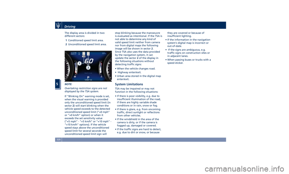
The display area is divided in two
different sectors:
1 Conditioned speed limit area.
2 Unconditioned speed limit area.
NOTE:
Overtaking restriction signs are not
displayed by the TSA system.
If “Blinking On” warning mode is set,
when the visual warning is provided
only the unconditioned speed limit (in
sector 2 ) will start blinking when the
vehicle speed exceeds to the detected
unconditioned speed limit (“+0 mph”
or “+0 km/h” option) or when it
exceeds the set sensitivity value
(“+5 mph” - “+5 km/h” or “+10 mph” -
“+10 km/h” options). If the vehicle
speed stays above the unconditioned
speed limit for several seconds the
unconditioned speed limit sign will stop blinking because the manoeuvre
is evaluated as intentional. If the TSA is
not able to determine any kind of
valid speed limit neither from camera
nor from digital maps the following
image will be shown in sector 2 .
Since TSA also uses the data provided
by the navigation system, it can
update the sector 2 of the display in
the following situations without
detecting traffic signs:
• When the vehicle changes road.
• Highway enter/exit.
• Urban area stored in the digital map
enter/exit.
System Limitations TSA may be impaired or may not
function in the following situations:
• If there is poor visibility, e.g. due to
insufficient illumination of the road,
if there are highly variable shade
conditions or in rain, snow or fog.
• If there is glare, e.g. from oncoming
traffic, direct sunlight or reflections
from other vehicles.
• If the windshield in the area of the
camera is dirty, or if the camera is
fogged up, damaged or covered.
• If the traffic signs are hard to detect,
e.g. due to dirt or snow, or because they are covered or because of
insufficient lighting.
• If the information in the navigation
system's digital map is incorrect or
out-of-date.
• If the signs are ambiguous, e.g.
traffic signs on construction sites or
in adjacent lanes.
• When passing buses or trucks with a
speed sticker.Driving
5
320
Page 354 of 436

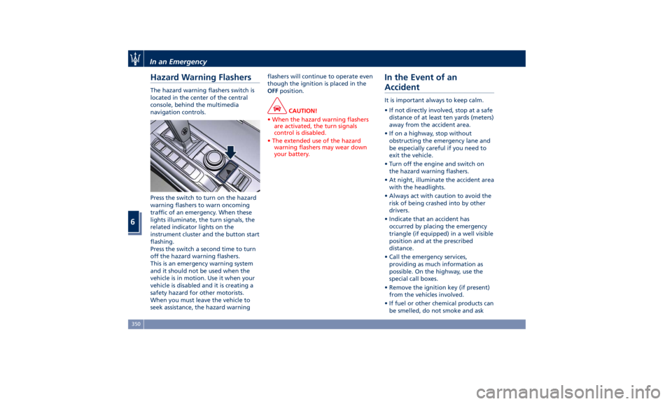
Hazard Warning Flashers The hazard warning flashers switch is
located in the center of the central
console, behind the multimedia
navigation controls.
Press the switch to turn on the hazard
warning flashers to warn oncoming
traffic of an emergency. When these
lights illuminate, the turn signals, the
related indicator lights on the
instrument cluster and the button start
flashing.
Press the switch a second time to turn
off the hazard warning flashers.
This is an emergency warning system
and it should not be used when the
vehicle is in motion. Use it when your
vehicle is disabled and it is creating a
safety hazard for other motorists.
When you must leave the vehicle to
seek assistance, the hazard warning flashers will continue to operate even
though the ignition is placed in the
OFF position.
CAUTION!
• When the hazard warning flashers
are activated, the turn signals
control is disabled.
• The extended use of the hazard
warning flashers may wear down
your battery.
In the Event of an
Accident It is important always to keep calm.
• If not directly involved, stop at a safe
distance of at least ten yards (meters)
away from the accident area.
• If on a highway, stop without
obstructing the emergency lane and
be especially careful if you need to
exit the vehicle.
• Turn off the engine and switch on
the hazard warning flashers.
• At night, illuminate the accident area
with the headlights.
• Always act with caution to avoid the
risk of being crashed into by other
drivers.
• Indicate that an accident has
occurred by placing the emergency
triangle (if equipped) in a well visible
position and at the prescribed
distance.
• Call the emergency services,
providing as much information as
possible. On the highway, use the
special call boxes.
• Remove the ignition key (if present)
from the vehicles involved.
• If fuel or other chemical products can
be smelled, do not smoke and askIn an Emergency
6
350
Page 356 of 436

(Continued)
go back to normal operation.
NOTE:
The compact spare wheel is supplied in
aluminum or steel: the pictures show
the one in aluminum.
The compact spare wheel is stored in
the trunk and is supplied deflated in
order to limit the amount of space
occupied. An electric compressor is also
provided for inflating. In the event of
a tire puncture, proceed as follows.
• Stop the vehicle in a place that does
not constitute a danger to traffic and
where the wheel can be changed
safely. The vehicle must be level and
on firm ground.
• Select the P (Park) mode and then
engage manually the electric parking
brake and move the ignition switch
to OFF position.
• If necessary, turn the hazard warning
flashers on and place the warning
triangle (if equipped) at the required
distance.
WARNING!
• The jack should be used on level firm
ground wherever possible. • It is recommended that the wheels
of the vehicle be chocked, and that
no person should remain in a vehicle
that is being jacked.
• If the vehicle has been stopped on a
slope or an uneven surface, place
chocks or other suitable items in
front of or behind the wheels to
stop the vehicle from moving.
• Never start or run the engine with
the vehicle on a jack.
• No person should place any portion
of their body under a vehicle that is
supported by a jack.
• Lift the ground coverage of the
trunk
(see chapter “T ool Kit” in this
section).
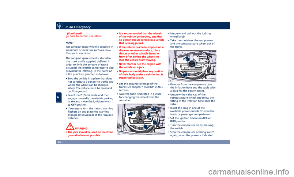
• Take the tools (indicated in picture)
for changing the wheel from the
container. • Unscrew and pull out the locking
wheel knob.
• Take the container, the compressor
and the compact spare wheel out of
the trunk.
• Remove from the compressor case
the inflation hose and the cable with
a plug for the power outlet.
• Unscrew the valve cap of the
compact spare wheel and screw the
fitting of the inflation hose onto the
valve.
• Insert the plug in one of the
available power outlets fitted in the
trunk or passenger compartment.
• Set the ignition device on ACC or
RUN position.
• Turn the compressor on by pressing
the switch.
• Stop the compressor pressing switch
again, when the pressure indicatedIn an Emergency
6
352
Page 393 of 436

Ref. Type Function
39 Mini – 7,5A Flow meters,
tank lackage,
canister, exhaust
by-pass valve
relay coil and air
shutter
48 – –
49 Mini – 10A Pedal brake
switch-TCM
module
50 Mini – 15A +30 PCM module
51 Mini – 30A Fuel pump relay
input
52 Mini – 5A Starter solenoid
signal for PCM
and voltage
stabilizer
53 Mini – 10A AWD module
Rear Power Distribution Center • To access the center it is necessary to
lift the ground coverage of the trunk
compartment (see chapter “Tool Kit”
in section “In an Emergency”) and
remove the storage box.
• To access the fuses, release the cover
latch shown in picture. • Press the release latch and lift the lid
from this side.
• Push the lid toward the right side to
release the indicated latches on the
unit.
The table points out the position as
featured in the figure, the type and
function of the fuses on the rear area
distribution control unit. Ref. Type Function
2 Maxi – 40A BCM module
3 Maxi – 40A BCM module
4 Maxi – 30A BCM module
5 Maxi – 30A BCM module
6 Maxi – 20A Trailer harness
(not for TROFEO
version)
7 Maxi – 30A Driver door
module
8 Maxi – 30A Passenger door
module
9 Maxi – 40A Start&Stop:
voltage
stabilizer,
dashboard
10 Maxi – 40A Start&Stop:
voltage
stabilizer, body
11 Maxi – 40A “High Premium”
stereo amplifier
unit
Maxi – 20A “Premium”
stereo amplifier
unit (1)
15 Maxi – 40A HVAC front
blower relay coilMaintenance and Care
7
389
Page 396 of 436

Fuse Box under the Dashboard This box is located in an internal area
under the dashboard left side.
Considering the complexity of this
operation, we recommend having the
fuses replaced by an Authorized
Maserati Dealer .
The table points out the position as
featured in the figure, the type and
function of the fuses in the box under
the dashboard.
Ref. Type Function
1 Mini – 7,5A Cluster module,
USB charger, CSS,
SGW and DSRC
(Japan version
only)
2 Mini – 15A Cluster module,
clock
3 Mini – 10A DSRC and DTV
system (Japan
version only)
4 Mini – 5A E-call
5 Mini – 7,5A Security Gateway
6 Mini – 15A Radio
7 Mini – 10A Column software
module, CSS Ref. Type Function
8 Mini – 10A Start & Stop
switch,
diagnostic outlet
Maintenance and Care
7
392
Page 432 of 436

Passenger Seat Belts ..........61
Seat Belt Reminder Light ..... .164
Seat Belts and Pregnant Women . .65
Seat Belts Pretensioners ........63
Three-Point Seat Belts .........59
Three-Point Seat Belts Height
Adjustment ................61
Three-Point Seat Belts Untwisting
Procedure .................61
Three-Point Seat Belts Use
Instructions ................59
Using the Seat Belt in Automatic
Locking Retractor Mode (ALR) . . .63
Seats ......................97
Driver Memory Seat ........ .101
Easy Entry/Exit Seats ........ .102
Front Heated Seats ...........99
Front Power Seats ............97
Front Ventilated Seats ....... .100
Power Lumbar Seats ..........98
Rear Armrest ............. .104
Rear Seat Folding Seatback . . . .103
Rear Seats ............... .103
Rear Side Heated Seats ...... .104
Seat Adjustment .............98
Service .....................10
Siri Smart Personal Assistant .... .225
SmartBeam System ........... .116
Smoking Kit ................ .137
Snow Chains ............... .328
Spare parts service
Genuine Parts ..............13
Scheduled Maintenance .......13 Spare Parts Service .............13
SRS (Supplemental Restraint
System) ....................65
Start&Stop System ........... .230
Occupant Safety Function .... .232
Start&Stop Active Indicator . . . .163
Start&Stop Disable Indicator . . . .182
Start&Stop Failure Indicator
Light ................... .182
Start&Stop Function Disabling
Indicator ................ .232
Start&Stop Menu .......... .172
Start&Stop System Failure .... .234
Start the Engine
Engine Start Failure ......... .229
Engine Turn Off ........... .230
Steering Wheel .............
.108
Heated
Steering Wheel ...... .108
Phone
and Voice Controls on
Steering Wheel ............ .224
Sunroof
Initialization Procedure ...... .149
Pinch Protect Feature ....... .149
Slide Opening Sunroof ....... .148
Sunroof Maintenance ....... .150
Venting Sunroof ........... .149
Sunshades ...................48
Sun Visors ................. .137
Surround View Camera System ....87
Symbols ....................14
Danger Symbols .............14 Symbols of Prohibitions and
Compulsory Measures .........14
Tank fuel refill .............. .336
TCS (Traction Control System) .... .275
Technical Data .............. .411
Telltales
Telltales on Speedometer ..... .161
Telltales on Tachometer ...... .163
Tires
Change a Tire ............. .351
Compact spare tire ......... .329
Department of Transportation
Uniform Tire Quality Grades . . . .325
General Information ........ .321
Inflation Pressure .......... .420
Pneumatic Suspension Mode for
Wheel Change ............ .329
Punctured Tire, use ......... .351
Replacement Tires .......... .327
Tire Pressure .............. .325
Tire Pressure Checkup ....... .326
Tire Safety Information ...... .321
TPMS - Tire Pressure Monitoring
System .................. .329
Tread Wear Indicators ....... .326
Winter Tires .............. .328
ToolKit................... .348
Towing
Towing a Disabled Vehicle .... .360
Towing the Vehicle ......... .360
Use
the Vehicle Tow Hook .... .360
Vehicle Towing Conditions .... .360Index
9 428