Page 149 of 436
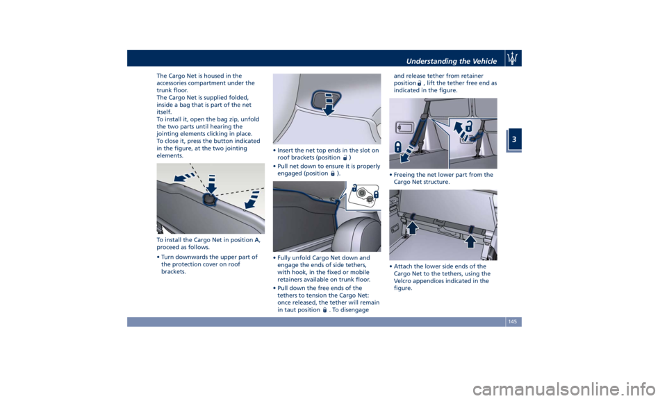
The Cargo Net is housed in the
accessories compartment under the
trunk floor.
The Cargo Net is supplied folded,
inside a bag that is part of the net
itself.
To install it, open the bag zip, unfold
the two parts until hearing the
jointing elements clicking in place.
To close it, press the button indicated
in the figure, at the two jointing
elements.
To install the Cargo Net in position A ,
proceed as follows.
• Turn downwards the upper part of
the protection cover on roof
brackets. • Insert the net top ends in the slot on
roof brackets (position
)
• Pull net down to ensure it is properly
engaged (position
).
• Fully unfold Cargo Net down and
engage the ends of side tethers,
with hook, in the fixed or mobile
retainers available on trunk floor.
• Pull down the free ends of the
tethers to tension the Cargo Net:
once released, the tether will remain
in taut position
. To disengage and release tether from retainer
position
, lift the tether free end as
indicated in the figure.
• Freeing the net lower part from the
Cargo Net structure.
• Attach the lower side ends of the
Cargo Net to the tethers, using the
Velcro appendices indicated in the
figure.Understanding the Vehicle
3
145
Page 150 of 436
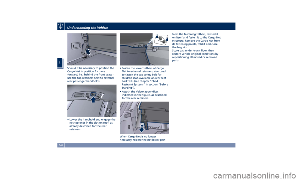
Should it be necessary to position the
Cargo Net in position B - more
forward, i.e., behind the front seats -
use the top retainers next to external
rear passenger handholds.
• Lower the handhold and engage the
net top ends in the slot on roof, as
already described for the rear
retainers. • Fasten the lower tethers of Cargo
Net to external retainers, also used
to fasten the top safety belt for
children seat, available on rear seat
backrests (see chapter “Child
Restraint Systems” in section “Before
Starting”).
• Attach the Velcro appendices
indicated in the figure, as described
for the rear retainers.
When Cargo Net is no longer
necessary, release the net lower part from the fastening tethers, rewind it
on itself and fasten it to the Cargo Net
structure. Remove the Cargo Net from
its fastening points, fold it and close
the bag zip.
Store bag under trunk floor, then
restore vehicle original conditions by
repositioning all moved or removed
parts.Understanding the Vehicle
3
146
Page 217 of 436
• After removing the molding, take
the screwdriver from the tool kit
under trunk mat (see “Tool kit” in
section “In an Emergency”).
• Insert screwdriver tip inside the hole
on LH side of glove box structure:
push until home against actuator
pin.
• Push down screwdriver tip to release
actuator pin and manually unlock
the glove box. The actuator will
remain in this condition until battery
feed is restored. • Reinstall the molding ensuring that
pins match with the clips of
dashboard structure.
• Press on the molding, always starting
from the central part until all 10 pins
are engaged in their clips and “click”
in place.
After releasing the glove box by
means of this procedure, do not lock
glove box using the PIN code and
contact an Authorized Maserati Dealer to have unlock feature via PIN
code checked.
Inner SectionDashboard Instruments and Controls
4
213
Page 342 of 436
Fuel Filler Cap Open Warning
Light After refueling the car
performs a check of the fuel
filler cap and the amber
warning light on the TFT
display comes on if it is not correctly
closed, after approximately 10 minutes
also depending on driving conditions.
If the problem is in the fuel system, the
Malfunction Indicator Light
also
comes on.
If the fuel filler cap is locked and the
issue remains in the system, at the next
engine start only the Malfunction
Indicator Light
comes on. In this
case, contact an Authorized Maserati
Dealer .
Emergency Fuel Filler Door
Release If you are unable to unlock the fuel
filler door using the key fob RKE
transmitter, use the fuel filler door
emergency release located in the
trunk.
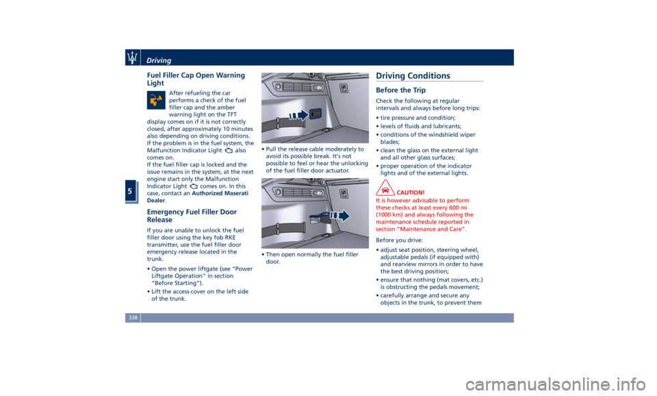
• Open the power liftgate (see “Power
Liftgate Operation” in section
“Before Starting”).
• Lift the access cover on the left side
of the trunk. • Pull the release cable moderately to
avoid its possible break. It's not
possible to feel or hear the unlocking
of the fuel filler door actuator.
• Then open normally the fuel filler
door.Driving Conditions Before the Trip Check the following at regular
intervals and always before long trips:
• tire pressure and condition;
• levels of fluids and lubricants;
• conditions of the windshield wiper
blades;
• clean the glass on the external light
and all other glass surfaces;
• proper operation of the indicator
lights and of the external lights.
CAUTION!
It is however advisable to perform
these checks at least every 600 mi
(1000 km) and always following the
maintenance schedule reported in
section “Maintenance and Care”.
Before you drive:
•
adjust seat position, steering wheel,
adjustable pedals (if equipped with)
and rearview mirrors in order to have
the best driving position;
• ensure that nothing (mat covers, etc.)
is obstructing the pedals movement;
• carefully arrange and secure any
objects in the trunk, to prevent themDriving
5
338
Page 347 of 436
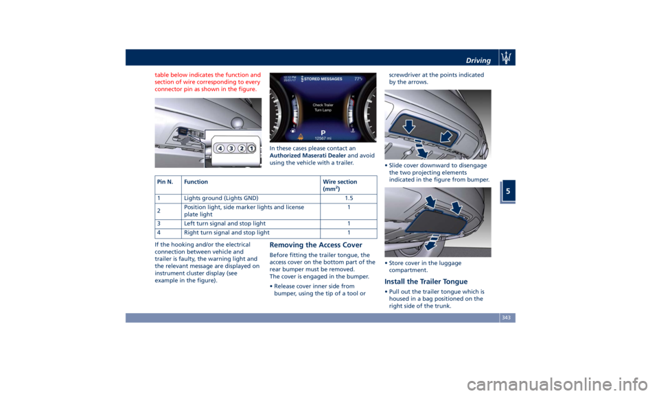
table below indicates the function and
section of wire corresponding to every
connector pin as shown in the figure.
If the hooking and/or the electrical
connection between vehicle and
trailer is faulty, the warning light and
the relevant message are displayed on
instrument cluster display (see
example in the figure). In these cases please contact an
Authorized Maserati Dealer and avoid
using the vehicle with a trailer.
Removing the Access Cover Before fitting the trailer tongue, the
access cover on the bottom part of the
rear bumper must be removed.
The cover is engaged in the bumper.
• Release cover inner side from
bumper, using the tip of a tool or screwdriver at the points indicated
by the arrows.
• Slide cover downward to disengage
the two projecting elements
indicated in the figure from bumper.
• Store cover in the luggage
compartment.
Install the Trailer Tongue • Pull out the trailer tongue which is
housed in a bag positioned on the
right side of the trunk.Pin N. Function Wire section
(mm 2
)
1 Lights ground (Lights GND) 1.5
2 Position light, side marker lights and license
plate light 1
3 Left turn signal and stop light 1
4 Right turn signal and stop light 1 Driving
5
343
Page 352 of 436
Tool Kit The tools are located in the trunk
inside a preformed container.
To access the tools, lift the rear part of
the trunk cargo floor, by acting on the
handle.
It is possible to maintain the cargo
floor in the lifted position when trunk
cover is not hooked to liftgate (figure
1 ), is hooked to liftgate (figure 2 )oris
removed (figure 3 ).
The straps for fastening the cargo
floor can be found at the ends and
along the band fastened by means of
Velcro inserts on the floor back side.
Once cargo floor is lifted, release the
strap and fasten it at the positions
shown in the figures below.
Remove the storage box.In an Emergency
6
348
Page 387 of 436
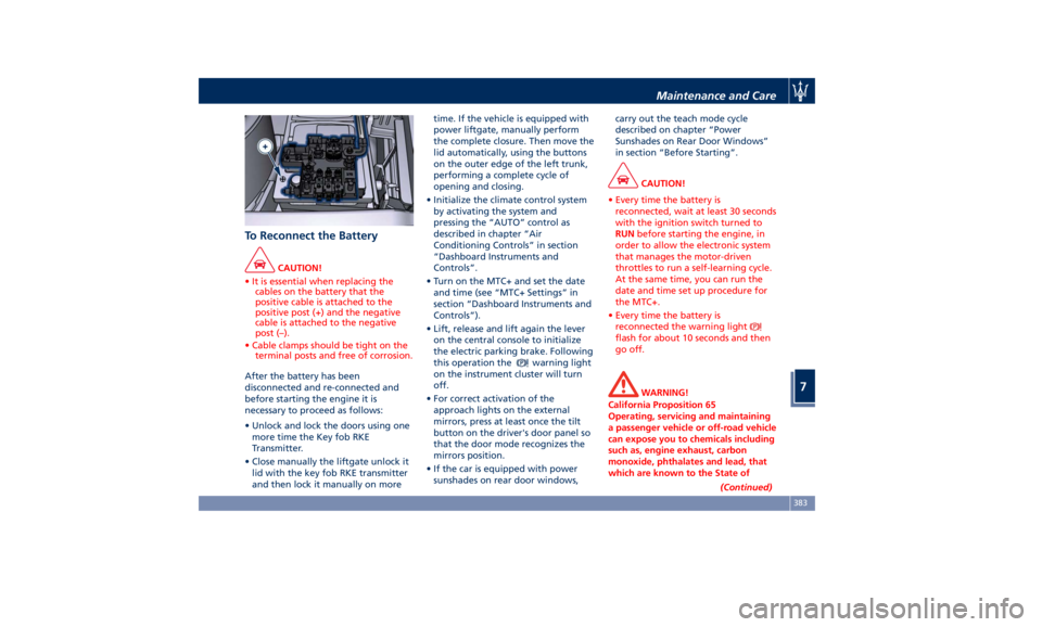
To Reconnect the Battery CAUTION!
• It is essential when replacing the
cables on the battery that the
positive cable is attached to the
positive post (+) and the negative
cable is attached to the negative
post (–).
• Cable clamps should be tight on the
terminal posts and free of corrosion.
After the battery has been
disconnected
and re-connected and
before starting the engine it is
necessary to proceed as follows:
• Unlock and lock the doors using one
more time the Key fob RKE
Transmitter.
• Close manually the liftgate unlock it
lid with the key fob RKE transmitter
and then lock it manually on more time. If the vehicle is equipped with
power liftgate, manually perform
the complete closure. Then move the
lid automatically, using the buttons
on the outer edge of the left trunk,
performing a complete cycle of
opening and closing.
• Initialize the climate control system
by activating the system and
pressing the “AUTO” control as
described in chapter “Air
Conditioning Controls” in section
“Dashboard Instruments and
Controls”.
• Turn on the MTC+ and set the date
and time (see “MTC+ Settings” in
section “Dashboard Instruments and
Controls”).
• Lift, release and lift again the lever
on the central console to initialize
the electric parking brake. Following
this operation the
warning light
on the instrument cluster will turn
off.
• For correct activation of the
approach lights on the external
mirrors, press at least once the tilt
button on the driver's door panel so
that the door mode recognizes the
mirrors position.
• If the car is equipped with power
sunshades on rear door windows, carry out the teach mode cycle
described on chapter “Power
Sunshades on Rear Door Windows”
in section “Before Starting”.
CAUTION!
• Every time the battery is
reconnected, wait at least 30 seconds
with the ignition switch turned to
RUN before starting the engine, in
order to allow the electronic system
that manages the motor-driven
throttles to run a self-learning cycle.
At the same time, you can run the
date and time set up procedure for
the MTC+.
• Every time the battery is
reconnected the warning light
flash for about 10 seconds and then
go off.
WARNING!
California Proposition 65
Operating, servicing and maintaining
a passenger vehicle or off-road vehicle
can expose you to chemicals including
such as, engine exhaust, carbon
monoxide, phthalates and lead, that
which are known to the State of
(Continued)Maintenance and Care
7
383
Page 393 of 436

Ref. Type Function
39 Mini – 7,5A Flow meters,
tank lackage,
canister, exhaust
by-pass valve
relay coil and air
shutter
48 – –
49 Mini – 10A Pedal brake
switch-TCM
module
50 Mini – 15A +30 PCM module
51 Mini – 30A Fuel pump relay
input
52 Mini – 5A Starter solenoid
signal for PCM
and voltage
stabilizer
53 Mini – 10A AWD module
Rear Power Distribution Center • To access the center it is necessary to
lift the ground coverage of the trunk
compartment (see chapter “Tool Kit”
in section “In an Emergency”) and
remove the storage box.
• To access the fuses, release the cover
latch shown in picture. • Press the release latch and lift the lid
from this side.
• Push the lid toward the right side to
release the indicated latches on the
unit.
The table points out the position as
featured in the figure, the type and
function of the fuses on the rear area
distribution control unit. Ref. Type Function
2 Maxi – 40A BCM module
3 Maxi – 40A BCM module
4 Maxi – 30A BCM module
5 Maxi – 30A BCM module
6 Maxi – 20A Trailer harness
(not for TROFEO
version)
7 Maxi – 30A Driver door
module
8 Maxi – 30A Passenger door
module
9 Maxi – 40A Start&Stop:
voltage
stabilizer,
dashboard
10 Maxi – 40A Start&Stop:
voltage
stabilizer, body
11 Maxi – 40A “High Premium”
stereo amplifier
unit
Maxi – 20A “Premium”
stereo amplifier
unit (1)
15 Maxi – 40A HVAC front
blower relay coilMaintenance and Care
7
389