2019 MASERATI LEVANTE clock
[x] Cancel search: clockPage 218 of 436
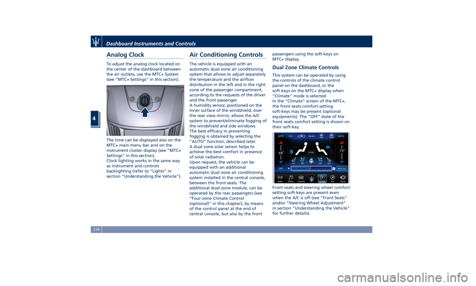
Analog Clock To adjust the analog clock located on
the center of the dashboard between
the air outlets, use the MTC+ System
(see “MTC+ Settings” in this section).
The time can be displayed also on the
MTC+ main menu bar and on the
instrument cluster display (see “MTC+
Settings” in this section).
Clock lighting works in the same way
as instrument and controls
backlighting (refer to “Lights” in
section “Understanding the Vehicle”). Air Conditioning Controls The vehicle is equipped with an
automatic dual-zone air conditioning
system that allows to adjust separately
the temperature and the airflow
distribution in the left and in the right
zone of the passenger compartment,
according to the requests of the driver
and the front passenger.
A humidity sensor, positioned on the
inner surface of the windshield, over
the rear view mirror, allows the A/C
system to prevent/eliminate fogging of
the windshield and side windows.
The best efficacy in preventing
fogging is obtained by selecting the
“AUTO” function, described later.
A dual zone solar sensor helps to
achieve the best comfort in presence
of solar radiation.
Upon request, the vehicle can be
equipped with an additional
automatic dual-zone air conditioning
system installed in the central console,
between the front seats. The
additional dual-zone module, can be
operated by the rear passengers (see
“Four-zone Climate Control
(optional)” in this chapter), by means
of the control panel at the end of
central console, but also by the front passengers using the soft-keys on
MTC+ display.
Dual Zone Climate Controls This system can be operated by using
the controls of the climate control
panel on the dashboard, or the
soft-keys on the MTC+ display when
“Climate” mode is selected.
In the "Climate" screen of the MTC+,
the front seats comfort setting
soft-keys may be present (optional
equipments). The “OFF” state of the
front seats comfort setting is shown on
their soft-key.
Front seats and steering wheel comfort
setting soft-keys are present even
when the A/C is off (see "Front Seats"
and/or "Steering Wheel Adjustment"
in section "Understanding the Vehicle"
for further details).Dashboard Instruments and Controls
4
214
Page 340 of 436
(Continued)
with proper maintenance. Have the
exhaust system inspected every time
the vehicle is raised. Have any
abnormal conditions repaired
promptly. Until repaired, drive with
all side windows fully open.
WARNING!
California Proposition 65
Operating, servicing and maintaining
a passenger vehicle or off-road vehicle
can expose you to chemicals including
such as, engine exhaust, carbon
monoxide, phthalates and lead, that
which are known to the State of
California to cause cancer and birth
defects or other reproductive harm. To
minimize exposure, avoid breathing
exhaust, do not idle the engine except
as necessary, service your vehicle in a
well-ventilated area and wear gloves
or wash your hands frequently when
servicing your vehicle. For more
information go to:
www.P65Warnings.ca.gov/passenger-
vehicle Refueling Fuel Filler Neck Access To access the fuel filler neck, the filler
door must be unlocked. From outside
the vehicle, this can only be done by
pressing the unlock
or the lock
button on the key fob RKE
transmitter, in the same way as if
opening or closing the doors. If any of
the door lock controls is pressed from
inside the vehicle, the filler door will
still remain open to allow refueling.
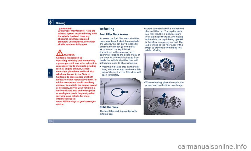
• Press the indicated area on the filler
door, which is located on the rear left
side of the vehicle: the filler door will
open completely.
Refill the Tank The fuel filler neck is provided with
external cap. • Rotate counterclockwise and remove
the fuel filler cap. The cap hermetic
seal may result in a slight pressure
increase inside the tank. Any hissing
noise while the cap is being opened
is therefore completely normal. The
cap is linked to the filler neck with a
strap, to prevent it from being lost
while refueling.
• When refueling, place the cap in the
proper seat on the filler door hinge.Driving
5
336
Page 341 of 436
• Insert the fuel nozzle fully into the
filler.
WARNING!
• To avoid the risk of fire, do not
approach the filler with open flames
or cigarettes!
• To avoid the risk of inhaling noxious
fumes, do not breathe close to the
fuel filler door, when opened.
• Never have any smoking materials
lit in or near the vehicle when the
fuel filler door is open or the tank is
being filled.
• Never add fuel when the engine is
running. This violates most
fire-prevention regulations and may
cause the Malfunction Indicator
Light
to turn on (see
“Instrument Cluster” in section
“Dashboard Instruments and
Controls”).
• Fill the vehicle with fuel. Fuel tank
capacity
is indicated in the
“Refillings” table in section
“Features and Specifications”.
When the fuel nozzle “clicks” or
shuts off, the fuel tank is basically
full: it is possible to further ensure
refueling by enabling the fuel nozzle additional fuel supply until two
clicks. After the two additional clicks,
the amount of fuel allowed by the
system is very low, we recommend
therefore not to persist further.
• Wait approximately 10 seconds
before removing the fuel nozzle in
order to ensure completed supply of
residual fuel and restrict the risk of
fouling the fuel filler door area.
• Remove the fuel nozzle.
• Insert the cap on the fuel filler neck.
• Tighten the cap, turning it clockwise
until it stops.
• Close the fuel filler door.
CAUTION!
To avoid fuel spillage and overfilling,
do not “top off” the fuel tank after
filling.
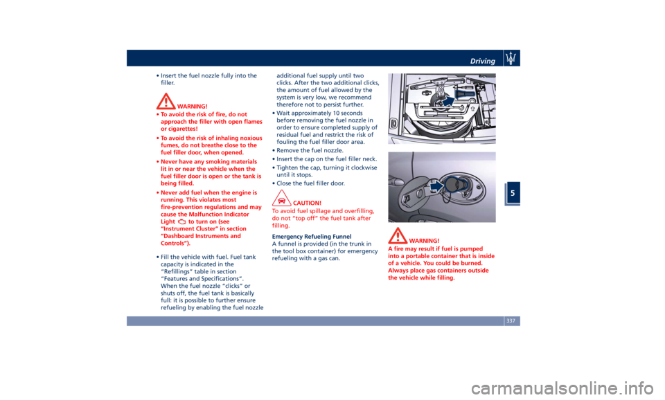
Emergency Refueling Funnel
A
funnel is provided (in the trunk in
the tool box container) for emergency
refueling with a gas can. WARNING!
A fire may result if fuel is pumped
into a portable container that is inside
of a vehicle. You could be burned.
Always place gas containers outside
the vehicle while filling.Driving
5
337
Page 357 of 436
by the gauge reaches the
recommended level (see “Tire
Inflation Pressure” in section
“Features and Specifications”) and
screw the cap on the compact spare
wheel valve.
WARNING!
• In order to obtain a more accurate
reading, the compressor should be
switched off when checking the tire
pressure of the compact spare wheel
on the pressure gauge.
• Do not run the compressor for more
than 20 minutes: there is a risk it
could overheat. Also, prolonged
power absorption may discharge the
battery, subsequently preventing
the engine from starting. • The compressor has been designed
exclusively to inflate compact spare
wheels; do not use it to inflate air
mattresses, dinghies etc.
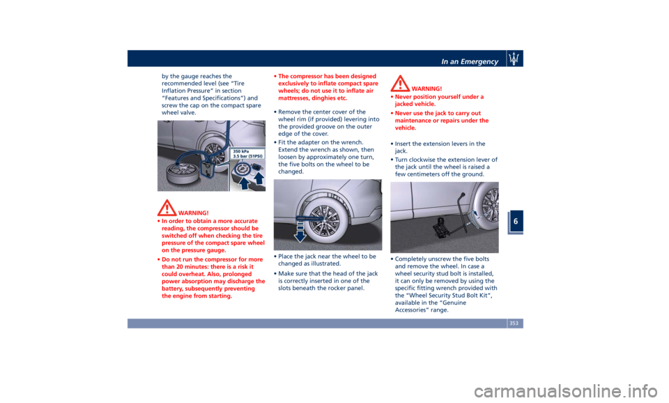
• Remove the center cover of the
wheel
rim (if provided) levering into
the provided groove on the outer
edge of the cover.
• Fit the adapter on the wrench.
Extend the wrench as shown, then
loosen by approximately one turn,
the five bolts on the wheel to be
changed.
• Place the jack near the wheel to be
changed as illustrated.
• Make sure that the head of the jack
is correctly inserted in one of the
slots beneath the rocker panel. WARNING!
• Never position yourself under a
jacked vehicle.
• Never use the jack to carry out
maintenance or repairs under the
vehicle.
• Insert the extension levers in the
jack.
•
Turn clockwise
the extension lever of
the jack until the wheel is raised a
few centimeters off the ground.
• Completely unscrew the five bolts
and remove the wheel. In case a
wheel security stud bolt is installed,
it can only be removed by using the
specific fitting wrench provided with
the “Wheel Security Stud Bolt Kit”,
available in the “Genuine
Accessories” range.In an Emergency
6
353
Page 358 of 436
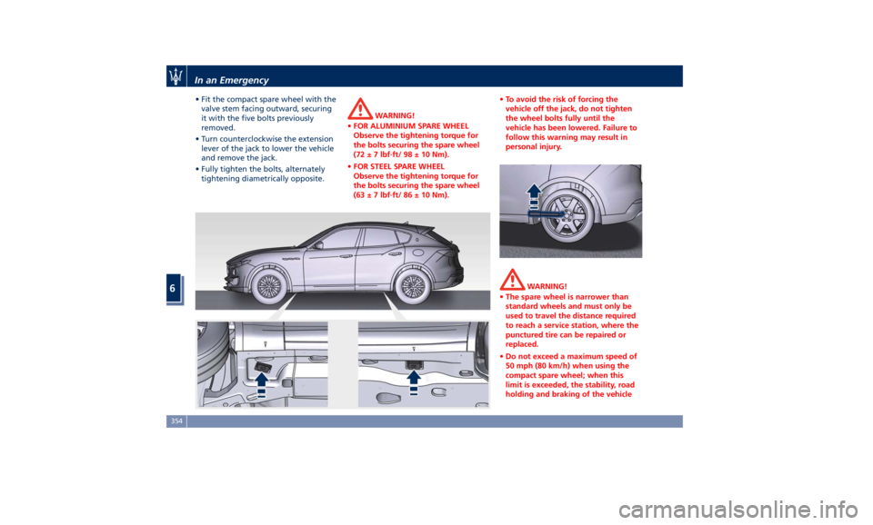
• Fit the compact spare wheel with the
valve stem facing outward, securing
it with the five bolts previously
removed.
• Turn counterclockwise the extension
lever of the jack to lower the vehicle
and remove the jack.
• Fully tighten the bolts, alternately
tightening diametrically opposite. WARNING!
• FOR ALUMINIUM SPARE WHEEL
Observe the tightening torque for
the bolts securing the spare wheel
(72 ± 7 lbf·ft/ 98 ± 10 Nm).
• FOR STEEL SPARE WHEEL
Observe the tightening torque for
the bolts securing the spare wheel
(63 ± 7 lbf·ft/ 86 ± 10 Nm). • To avoid the risk of forcing the
vehicle off the jack, do not tighten
the wheel bolts fully until the
vehicle has been lowered. Failure to
follow this warning may result in
personal injury.
WARNING!
• The spare wheel is narrower than
standard wheels and must only be
used to travel the distance required
to reach a service station, where the
punctured tire can be repaired or
replaced.
• Do not exceed a maximum speed of
50 mph (80 km/h) when using the
compact spare wheel; when this
limit is exceeded, the stability, road
holding and braking of the vehicleIn an Emergency
6
354
Page 396 of 436

Fuse Box under the Dashboard This box is located in an internal area
under the dashboard left side.
Considering the complexity of this
operation, we recommend having the
fuses replaced by an Authorized
Maserati Dealer .
The table points out the position as
featured in the figure, the type and
function of the fuses in the box under
the dashboard.
Ref. Type Function
1 Mini – 7,5A Cluster module,
USB charger, CSS,
SGW and DSRC
(Japan version
only)
2 Mini – 15A Cluster module,
clock
3 Mini – 10A DSRC and DTV
system (Japan
version only)
4 Mini – 5A E-call
5 Mini – 7,5A Security Gateway
6 Mini – 15A Radio
7 Mini – 10A Column software
module, CSS Ref. Type Function
8 Mini – 10A Start & Stop
switch,
diagnostic outlet
Maintenance and Care
7
392
Page 405 of 436
to clean the instrument cluster's
transparent dome, the MTC+ display,
the analog clock and the leather
upholstery. We recommended the use
of “Car Care” products approved by
Maserati for the maintenance and
care of the interior.
Leather Upholstery Treatment Have the leather upholstery only
treated, as provided in the Scheduled
Service Plan, by an Authorized
Maserati Dealer which has the
required specific products.
Parts in Premium Quality Wood Remove any dirt with a damp cloth.
NOTE:
The Authorized Maserati Dealer can
provide you with any information
about the Maserati approved “Car
Care” products, available in the
“Genuine Accessories” range.
WARNING!
California Proposition 65
Operating, servicing and maintaining
a passenger vehicle or off-road vehicle
can expose you to chemicals including
such as, engine exhaust, carbon monoxide, phthalates and lead, that
which are known to the State of
California to cause cancer and birth
defects or other reproductive harm. To
minimize exposure, avoid breathing
exhaust, do not idle the engine except
as necessary, service your vehicle in a
well-ventilated area and wear gloves
or wash your hands frequently when
servicing your vehicle. For more
information go to:
www.P65Warnings.ca.gov/passenger-
vehicle
MTC+ Touch Screen • Do NOT attach any object to the
touch screen, doing so can result in
damage to the touch screen.
• Do not touch the screen with any
hard or sharp objects (pen, USB stick,
jewelry, etc.) which could scratch the
touch screen surface.
• Do not spray any liquid or caustic
chemicals directly on the screen! Use
a clean and dry micro fiber lens
cleaning cloth in order to clean the
touch screen. If necessary, use a
lint-free cloth dampened with a
cleaning solution, such as isopropyl
alcohol, or an isopropyl alcohol and
water solution ratio of 50:50. Be sure to follow the solvent manufacturer’s
precautions and directions.
Maintenance and Care
7
401
Page 429 of 436

Infants and Child Restraints .....74
Installing Child Restraint Systems
using the Vehicle Seat Belt
equipped with ALR ...........76
Lower Anchors and Tether for
Children (LATCH) ............76
Older Children and Child
Restraints .................75
Tips on getting the most out of your
child restraint ..............76
Climate Control ............. .214
Clock, analog .............. .201
Console
Central Console Components ....95
Front Dome Console
Components ...............96
Controls Screen ............. .195
Cruise Control
Cruise Control Adaptive (ACC) . .286
Electronic Cruise Control (CC) . . .282
Cupholders ................ .134
Front Passengers Cupholders . . .134
Rear Passengers Cupholders . . . .135
Dashboard Compartment ...... .210
Dashboard Components .........94
Defroster ...................91
Doors
Child Protection Door Lock
System ...................41
Doors Locking ..............39
Doors Manual Lock ...........39
Front Doors Components ......96 Lock/Unlock Door Flashlight ....34
Power Doors Locking/Unlocking . .40
Rear Doors Components .......97
Soft Door Close System ........41
Unlock Driver Door/All Doors with
Key fob 1st Press ............34
Unlock the Vehicle with Key fob. .33
DPF System
DPF Filter Replacement ...... .377
“Drive Away Inhibit” strategy . . . .272
Drive Mode, controls ......... .244
Setting Ride Height ........ .258
Setting the Drive Mode ...... .245
Driving Conditions ........... .338
Before the Trip ............ .338
Driving at Night ........... .339
Driving in Fog ............ .340
Driving in Snow and Wet Grass . .266
Driving in the Mountains ..... .340
Driving in the Rain ......... .339
Driving on Snow or Ice ...... .340
Safe Driving .............. .339
DRL (Daytime Running Light) . . . .116
EDR (Event Data Recorder) .......73
Electronic Cruise Control .......
.282
Emergency ...................
5
Hazard W arning
Lights ...... .128
In the Event of an Accident . . . .350
Jump Starting ............ .357
Use the Vehicle Tow Hook .... .360
Engine
Engine Coolant Level Check . . . .374 Engine Oil Level Check ...... .377
Hood ....................56
Normal Starting of the Engine . .228
Use of the Engine .......... .281
Entry/Exit, lights on ............30
EPB (Electric Parking Brake) ..... .268
ESC (Electronic Stability Control) . .273
Filters
A/C System Air Filter
Replacement ............. .379
Engine Air Filter Replacement . .379
Forward Collision Warning (FCW) . .297
Fuel
Carbon Monoxide Warning . . . .335
Emergency Fuel Filler Door
Release ................. .338
Emissions Inspection and
Maintenance Programs ...... .369
Fuel Consumption ......... .410
Fuel Filter Service .......... .377
Fuel Requirements ......... .334
Fuel System Warnings ....... .335
Gasoline/Oxygenate Blends . . . .334
Low Fuel Indicator ......... .181
Materials Added to Fuel ..... .335
MMT in Gasoline .......... .335
Reformulated Gasoline ...... .334
Fuses .................... .386
Fuses Position ............ .386
Fuses Replacement ......... .386
Glove Box Lock Feature ....... .211Index
9 425