Page 252 of 296

(Continued)
quick coupling from the negative
pole (–) of the battery.
If the battery needs to be removed
from
its compartment, you must first
detach the terminal clamp from
negative pole (–) and then the other
terminal clamp from positive pole (+),
after removing the protective cover.
Battery poles are marked positive (+)
and negative (–) and are identified on
the battery case.
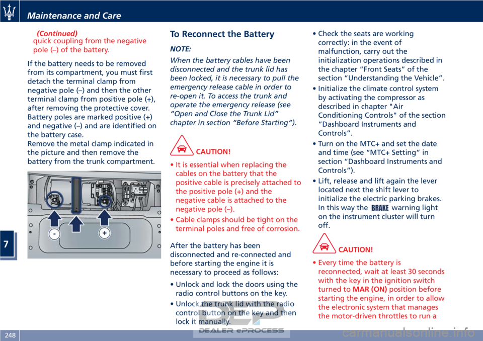
Remove the metal clamp indicated in
the picture and then remove the
battery from the trunk compartment.
To Reconnect the Battery
NOTE:
When the battery cables have been
disconnected and the trunk lid has
been locked, it is necessary to pull the
emergency release cable in order to
re-open it. To access the trunk and
operate the emergency release (see
“Open and Close the Trunk Lid”
chapter in section “Before Starting”).
CAUTION!
• It is essential when replacing the cables on the battery that the
positive cable is precisely attached to
the positive pole (+) and the
negative cable is attached to the
negative pole (–).
• Cable clamps should be tight on the terminal poles and free of corrosion.
After the battery has been
disconnected
and re-connected and
before starting the engine it is
necessary to proceed as follows:
• Unlock and lock the doors using the radio control buttons on the key.
• Unlock the trunk lid with the radio control button on the key and then
lock it manually. • Check the seats are working
correctly: in the event of
malfunction, carry out the
initialization operations described in
the chapter “Front Seats” of the
section “Understanding the Vehicle”.
• Initialize the climate control system by activating the compressor as
described in chapter "Air
Conditioning Controls" of the section
“Dashboard Instruments and
Controls”.
• Turn on the MTC+ and set the date and time (see “MTC+ Setting” in
section “Dashboard Instruments and
Controls”).
• Lift, release and lift again the lever located next the shift lever to
initialize the electric parking brakes.
In this way the
warning light
on the instrument cluster will turn
off.
CAUTION!
• Every time the battery is reconnected, wait at least 30 seconds
with the key in the ignition switch
turned to MAR (ON) position before
starting the engine, in order to allow
the electronic system that manages
the motor-driven throttles to run a
Maintenance and Care
7
248
Page 253 of 296

self-learning cycle. At the same time,
you can run the date and time set up
procedure for the MTC.
• Every time the battery is reconnected the
and
warning lights will flash for
about 10 seconds and then go off.
WARNING!
California Proposition 65
Operating, servicing and maintaining
a passenger vehicle or off-road vehicle
can expose you to chemicals including
such as, engine exhaust, carbon
monoxide, phthalates and lead, that
which are know to the State of
California to cause cancer and birth
defects or other reproductive harm. To
minimize exposure, avoid breathing
exhaust, do not idle the engine except
as necessary, service your vehicle in a
well-ventilated area and wear gloves
or wash your hands frequently when
servicing your vehicle. For more
information go to:
www.P65Warnings.ca.gov/passenger-
vehicle
Useful Advice to Extend
Battery Life
When parking the vehicle, make sure
that the doors, front, rear lids and
flaps are properly closed. All interior
lights should be off.
When the engine is turned off, do not
keep the connected devices switched
on for a long time (such as radio,
hazard warning flashers, fan, etc.).
CAUTION!
If the battery charge remains below
50% for a long period of time, it will
be damaged due to sulfation; its
performance and starting power will
be reduced and it will be more subject
to freezing (this can happen even at
14°F/-10°C).
We recommend you to have the
battery
charge condition checked,
preferably at the beginning of the
cold season, to prevent the electrolyte
from freezing.
This check should be carried out more
frequently if the vehicle is used mainly
for short trips or if it is equipped with
power absorbing devices that remain
permanently on even when the
ignition switch is off. This applies above all if these devices have been
retrofitted ("Aftermarket" services).
If the vehicle is not used for long
periods of time, please see “Vehicle
Stored for Long Periods” in this
section.
Battery Recharge
WARNING!
The process of charging or recharging
the battery produces hydrogen, a
flammable gas that can explode and
cause serious injuries. When charging
or recharging the battery, follow the
recommended precautions at all
times.
• Before using a charger device
always check that this tool is
suitable for the installed battery,
with constant voltage (lower than
14.8 V) and low amperage
(maximum limit 15 A).
• Recharge the battery in a
well-ventilated environment.
• Never charge or recharge a frozen
battery: it can explode due to
hydrogen trapped inside the ice
crystals.
• Ensure that any sparks or open
(Continued)
Maintenance and Care
7
249
Page 259 of 296

Pos. Amp. –Color System / Component
F39 15 A – Blue NIM (Inside Roof
Node), NCL (Air
conditioning and
heating system
node), OBD socket,
CSA (Alarm system
siren ECU), CAV
(Motion sensing
alarm ECU), radio,
NAVTRAK
F40 30 A – Green Heated rear window
F41 - Not used
F42 7.5 A – Brown NCL and windshield
wiper control
F43 30 A – Green Windshield
wiper/washer
(Connected Devices
Relay INT/A)
F44 20 A – Yellow Front and rear power
outlets (INT/A device
relay) front seat
heating (passenger
side)
F45 - Not used
F46 20 A – Yellow NPG/NPP locksPos. Amp. –
Color System / Component
F47 30 A – Green NPG (Driver’s door
node)
F48 30 A – Green NPP (Passenger’s
door node)
F49 7.5 A – Brown NVO (Steering wheel
node), CSG (Power
steering ECU), CSP
(Twilight/rain sensor
ECU), NIM (Inside
Roof Node), NCL,
Radio, CEM, CRP,
domelight molding,
NAVTRAK
F50 7.5 A – Brown Air bag system
F51 7.5 A – Brown NCA (Automatic
Gearbox Node)
F52 15 A – Blue Front seat heating
(driver side) (INT/A
device relay)
F53 10 A – Red Rear fog lights
Fuses in Trunk Compartment
• To access the fuses, remove the floor
panel. • Remove the inside covering panel of
the battery compartment.
There are two control boxes.
• To access the fuses inside the control boxes, remove the covers by levering
up the fastening tabs.
Maintenance and Care
7
255