2019 LEXUS UX250H center
[x] Cancel search: centerPage 270 of 476

2705-1. Remote Touch
5-1.Remote Touch
■Switches“MAP” button (10.3-inch display
model)
Press this button to display the vehicle’s
current position.
“MENU” button
Press this button to display the menu
screen.
Back button
Press this button to display the previous
screen.
Touchpad
Slide your finger on the touchpad and
move the pointer to select a function, letter
and screen button.
Press the touchpad to enter the selected
function, letter or sc reen button. Certain
finger movements on the touchpad can
perform functions, such as changing map scalings and scrolling list screens.
Sub function button
When is displayed on the screen, a
function screen assigned to the screen can
be displayed.
“HOME” button (7-inch display
model)
Press this button to display the home
screen.
■Using the touchpad
1 Select: Touch the touchpad to
select the desired button on the
screen.
2 Enter: The buttons on the screen
can be selected by either depress-
ing or double tapping on the touch-
pad. Once a button has been
selected, the screen will change.
■Touch operation
Operations are performed by touching
the touchpad with your finger.
Trace
Trace the pad surface while maintaining
contact with the touch pad. Moving the
cursor and the pointer.
Remote Touch
The Remote Touch can be used to
operate Center Display. Owners of
models equipped with a navigation
system should refer to the “NAVI-
GATION AND MULTIMEDIA
SYSTEM OWNER’S MANUAL”.
Remote Touch operation
A
B
C
D
E
F
Page 271 of 476

2715-1. Remote Touch
5
Interior features
Double tap
Tap the touchpad twice, quickly. Select the
button on the screen.
Flick
Quick and long movement along the
touchpad with your finger. Move the list
screen.
Pinch in/Pinch out
Slide fingers toward each other or apart on
the touchpad. Change the scale of the
map.
■Menu screen
Press the “MENU” button on the
Remote Touch to display the menu
screen.
The display may differ depending on
the type of the system.
NOTICE
■To prevent damage to the Remote
Touch
Observe the following precautions. Fail-
ure to do so may cause damage to the
Remote Touch.
●Do not allow the Remote Touch to
come into contact with food, liquid,
stickers or lit cigarettes.
●Do not subject the Remote Touch to
excessive pressure or strong impact.
●Do not push the touchpad with a
strong force or use a sharp pointed
object to operate the pad.
Center Display overview
Page 297 of 476

2975-5. Using the storage features
5
Interior features
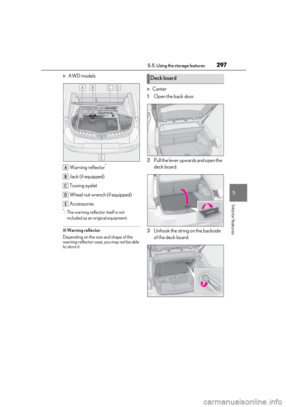
AWD modelsWarning reflector
*
Jack (if equipped)
Towing eyelet
Wheel nut wrench (if equipped)
Accessories
*: The warning reflector itself is not included as an original equipment.
■Warning reflector
Depending on the size and shape of the
warning reflector case, you may not be able
to store it.
Center
1 Open the back door.
2 Pull the lever upwards and open the
deck board.
3 Unhook the string on the backside
of the deck board.
A
B
C
D
E
Deck board
Page 304 of 476

3045-6. Using the other interior features
than the charging area. Additionally,
depending on the portable device, the
wireless charger may not operate
properly. Refer to the operation man-
ual of the portable device.
■The “Qi” symbol
The “Qi” symbol is a trademark of the
Wireless Power Consortium.
■Name for all parts
Operation indicator light
Power supply switch
Charge area
■Using the wireless charger
1 Press the power supply switch of
the wireless charger.
Pressing the switch ag ain turns the wireless
charger off. When turned on, the operation indicator
light (green) comes on.
When the power switch is turned off, the
on/off state of the wi
reless charger will be
memorized.
2 Place a portable device on the
charging area with its charging sur-
face facing down.
While charging, the operation indicator
light (orange) will be illuminated.
If charging does not begin, move the porta-
ble device as close to the center of the
charging area as possible.
When charging is complete, the operation
indicator light (green) will illuminate.
■Recharging function
If a certain amount of time has
elapsed since charging completed
and the portable device has not
been moved, the wireless charger
will restart charging.
If the portable device is moved
within the charging area, charging
will stop temporarily then restart.A
B
C
Page 305 of 476

3055-6. Using the other interior features
5
Interior features
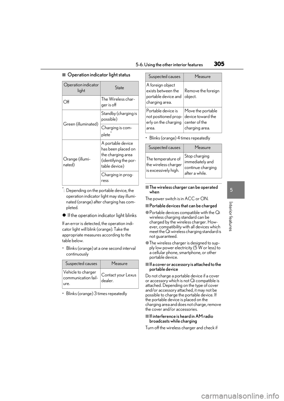
■Operation indicator light status
*: Depending on the portable device, the operation indicator light may stay illumi-
nated (orange) after charging has com-
pleted.
If the operation indicator light blinks
If an error is detected, the operation indi-
cator light will blink (orange). Take the
appropriate measures according to the
table below.
• Blinks (orange) at a one second interval continuously
• Blinks (orange) 3 times repeatedly • Blinks (orange) 4 times repeatedly
■The wireless charger can be operated
when
The power switch is in ACC or ON.
■Portable devices that can be charged
●Portable devices compatible with the Qi
wireless charging standard can be
charged by the wireless charger. How-
ever, compatibility with all devices which
meet the Qi wireless charging standard is
not guaranteed.
●The wireless charger is designed to sup-
ply low power electricity (5 W or less) to
a cellular phone, smartphone, or other
portable device.
■If a cover or accessory is attached to the
portable device
Do not charge a portable device if a cover
or accessory which is not Qi compatible is
attached. Depending on the type of cover
and/or accessory attached, it may not be
possible to charge the portable device. If
the portable device is placed on the
charging area and does not charge, remove
the cover and/or accessories.
■If interference is heard in AM radio
broadcasts while charging
Turn off the wireless charger and check if
Operation indicator lightState
OffThe Wireless char-
ger is off
Green (illuminated)
Standby (charging is
possible)
Charging is com-
plete
*
Orange (illumi-
nated)
A portable device
has been placed on
the charging area
(identifying the por-
table device)
Charging in prog-
ress
Suspected causesMeasure
Vehicle to charger
communication fail-
ure.Contact your Lexus
dealer.
Suspected causesMeasure
A foreign object
exists between the
portable device and
charging area.
Remove the foreign
object.
Portable device is
not positioned prop-
erly on the charging
area.Move the portable
device toward the
center of the
charging area.
Suspected causesMeasure
The temperature of
the wireless charger
is excessively high.Stop charging
immediately and
continue charging
after a while.
Page 361 of 476

3616-3. Do-it-yourself maintenance
6
Maintenance and care
The recommended cold tire inflation
pressure and tire size are displayed on
the tire and loading information label.
( P.422)
Tire valve Tire pressure gauge
1 Remove the tire valve cap.
2 Press the tip of the tire pressure
gauge onto the tire valve.
3 Read the pressure using the gauge
gradations.
4 If the tire inflation pressure is not at
the recommended level, adjust the
pressure.
If you add too much air, press the
center of the valve to deflate.
5 After completing the tire inflation
pressure measurement and adjust-
ment, apply soapy water to the
valve and check for leakage.
6 Put the tire valve cap back on.
■Tire inflation pressure check interval
You should check tire inflation pressure
every two weeks, or at least once a month.
Do not forget to check the spare.
■Effects of incorrect tire inflation pres-
sure
Driving with incorrect ti re inflation pressure
may result in the following:
●Reduced fuel economy
●Reduced driving comfort and poor han-
dling
●Reduced tire life due to wear
●Reduced safety
●Damage to the drive train
If a tire needs frequent inflating, have it
checked by your Lexus dealer.
■Instructions for checking tire inflation
pressure
When checking tire inflation pressure,
observe the following:
●Check only when the tires are cold.
If your vehicle has been parked for at
least 3 hours or has not been driven for
Tire inflation pressure
Checking the specified tire infla-
tion pressure
Inspection and adjustment pro-
cedure
A
B
Page 430 of 476

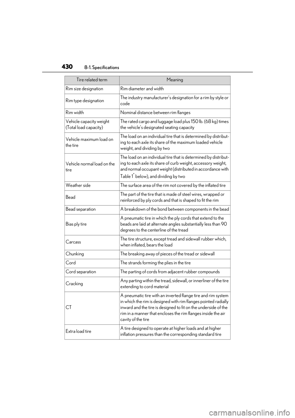
4308-1. Specifications
Rim size designationRim diameter and width
Rim type designationThe industry manufacturer’s designation for a rim by style or
code
Rim widthNominal distance between rim flanges
Vehicle capacity weight
(Total load capacity)The rated cargo and luggage load plus 150 lb. (68 kg) times
the vehicle’s designated seating capacity
Vehicle maximum load on
the tireThe load on an individual tire that is determined by distribut-
ing to each axle its share of the maximum loaded vehicle
weight, and dividing by two
Vehicle normal load on the
tire
The load on an individual tire that is determined by distribut-
ing to each axle its share of curb weight, accessory weight,
and normal occupant weight (distributed in accordance with
Table 1
* below), and dividing by two
Weather sideThe surface area of the rim not covered by the inflated tire
BeadThe part of the tire that is ma de of steel wires, wrapped or
reinforced by ply cords and th at is shaped to fit the rim
Bead separationA breakdown of the bond between components in the bead
Bias ply tire
A pneumatic tire in which the ply cords that extend to the
beads are laid at alternate angles substantially less than 90
degrees to the centerline of the tread
CarcassThe tire structure, except tread and sidewall rubber which,
when inflated, bears the load
ChunkingThe breaking away of pieces of the tread or sidewall
CordThe strands forming the plies in the tire
Cord separationThe parting of cords from adjacent rubber compounds
CrackingAny parting within the tread, side wall, or innerliner of the tire
extending to cord material
CT
A pneumatic tire with an inverted flange tire and rim system
in which the rim is designed wi th rim flanges pointed radially
inward and the tire is designed to fit on the underside of the
rim in a manner that encloses the rim flanges inside the air
cavity of the tire
Extra load tireA tire designed to operate at higher loads and at higher
inflation pressures than the corresponding standard tire
Tire related termMeaning
Page 432 of 476

4328-1. Specifications
*:Table 1 Occupant loading and distribution for vehicle normal load for various desig-
nated seating capacities
Pneumatic tire
A mechanical device made of rubber, chemicals, fabric and
steel or other materials, that, when mounted on an automo-
tive wheel, provides the traction and contains the gas or fluid
that sustains the load
Radial ply tire
A pneumatic tire in which the ply cords that extend to the
beads are laid at substantiall y 90 degrees to the centerline
of the tread
Reinforced tireA tire designed to operate at higher loads and at higher
inflation pressures than the corresponding standard tire
Section width
The linear distance between the exteriors of the sidewalls of
an inflated tire, excluding elevations due to labeling, decora-
tion, or protective bands
SidewallThat portion of a tire between the tread and bead
Sidewall separationThe parting of the rubber comp ound from the cord material
in the sidewall
Snow tire
A tire that attains a traction index equal to or greater than
110, compared to the ASTM E-1136 Standard Reference
Test Tire, when using the snow traction test as described in
ASTM F-1805-00, Standard Test Method for Single Wheel
Driving Traction in a Straight Line on Snow-and Ice-Cov-
ered Surfaces, and which is ma rked with an Alpine Symbol
( ) on at least one sidewall
Test rimThe rim on which a tire is fitt ed for testing, and may be any
rim listed as appropriate for use with that tire
TreadThat portion of a tire that comes into contact with the road
Tread ribA tread section running circ umferentially around a tire
Tread separationPulling away of the tread from the tire carcass
Treadwear indicators (TWI)The projections within the principal grooves designed to
give a visual indication of the degrees of wear of the tread
Wheel-holding fixtureThe fixture used to hold the wheel and tire assembly
securely during testing
Tire related termMeaning