2019 LEXUS UX200 warning light
[x] Cancel search: warning lightPage 47 of 452

471-2. Child safety
1
For safety and security
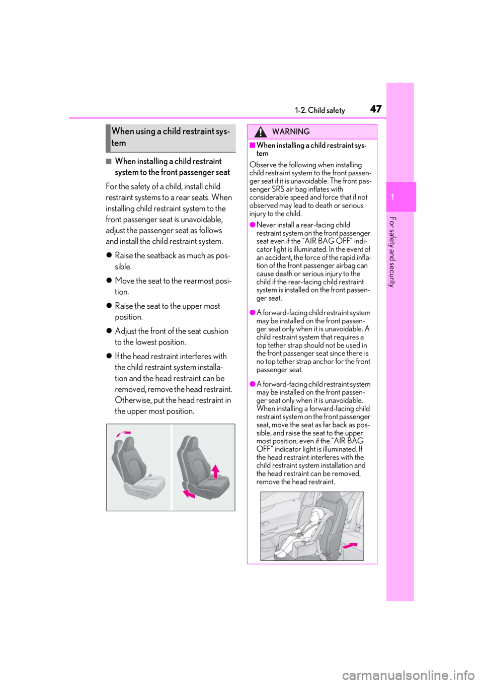
■When installing a child restraint
system to the front passenger seat
For the safety of a child, install child
restraint systems to a rear seats. When
installing child restraint system to the
front passenger seat is unavoidable,
adjust the passenger seat as follows
and install the child restraint system.
Raise the seatback as much as pos-
sible.
Move the seat to the rearmost posi-
tion.
Raise the seat to the upper most
position.
Adjust the front of the seat cushion
to the lowest position.
If the head restraint interferes with
the child restraint system installa-
tion and the head restraint can be
removed, remove the head restraint.
Otherwise, put the head restraint in
the upper most position.
When using a child restraint sys-
temWARNING
■When installing a child restraint sys-
tem
Observe the following when installing
child restraint system to the front passen-
ger seat if it is unavoidable. The front pas-
senger SRS air bag inflates with
considerable speed and force that if not
observed may lead to death or serious
injury to the child.
●Never install a rear-facing child
restraint system on the front passenger
seat even if the “AIR BAG OFF” indi-
cator light is illuminated. In the event of
an accident, the force of the rapid infla-
tion of the front passenger airbag can
cause death or serious injury to the
child if the rear-facing child restraint
system is installed on the front passen-
ger seat.
●A forward-facing child restraint system
may be installed on the front passen-
ger seat only when it is unavoidable. A
child restraint system that requires a
top tether strap should not be used in
the front passenger seat since there is
no top tether strap anchor for the front
passenger seat.
●A forward-facing child restraint system
may be installed on the front passen-
ger seat only when it is unavoidable.
When installing a forward-facing child
restraint system on the front passenger
seat, move the seat as far back as pos-
sible, and raise the seat to the upper
most position, even if the “AIR BAG
OFF” indicator light is illuminated. If
the head restraint interferes with the
child restraint system installation and
the head restraint can be removed,
remove the head restraint.
Page 67 of 452

67
2
2
Vehicle status information and indicators
Vehicle status informationand indicators
2-1. Instrument cluster
Warning lights and indicators . 68
Gauges and meters (except F SPORT models) ......................... 72
Gauges and meters (F SPORT models) .......................................... 75
Multi-information display.......... 79
Head-up display ........................... 86
Fuel consumption information 90
Page 68 of 452

682-1. Instrument cluster
2-1.Instrument cluster
For the purpose of explanation, the following illustrations display all warning lights
and indicators illuminated.
Except F SPORT models
F SPORT models
The location of warning lights and indicat ors may differ depending on the main
meter position.
Warning lights and indicators
The warning lights and indicators on th e instrument cluster, center panel and
outside rear view mirrors inform the driver of the status of the vehicle’s various
systems.
Warning lights and indicators displayed on the instrument cluster
Page 69 of 452

692-1. Instrument cluster
2
Vehicle status information and indicators
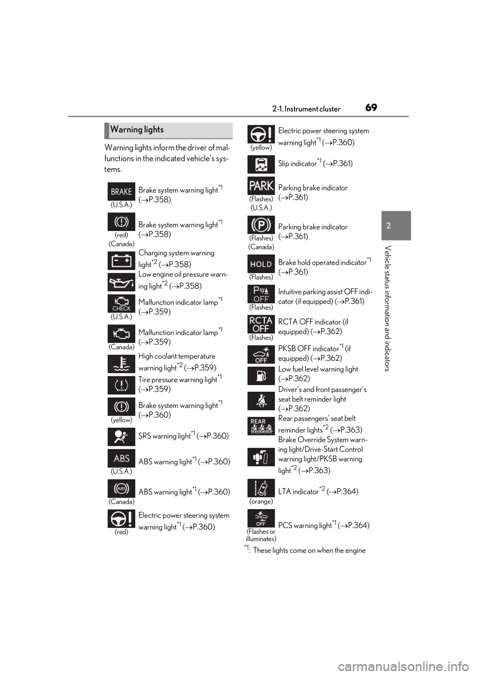
Warning lights inform the driver of mal-
functions in the indicated vehicle’s sys-
tems.
*1: These lights come on when the engine
Warning lights
(U.S.A.)
Brake system warning light*1
( P.358)
(red)
(Canada)
Brake system warning light*1
( P.358)
Charging system warning
light
*2 ( P.358)
Low engine oil pressure warn-
ing light
*2 ( P.358)
(U.S.A.)
Malfunction indicator lamp*1
( P.359)
(Canada)
Malfunction indicator lamp*1
( P.359)
High coolant temperature
warning light
*2 ( P.359)
Tire pressure warning light
*1
( P.359)
(yellow)
Brake system warning light*1
( P.360)
SRS warning light
*1 ( P.360)
(U.S.A.)
ABS warning light*1 ( P.360)
(Canada)
ABS warning light*1 ( P.360)
(red)
Electric power st eering system
warning light
*1 ( P.360)
(yellow)
Electric power steering system
warning light
*1 ( P.360)
Slip indicator
*1 ( P.361)
(Flashes)
(U.S.A.)
Parking brake indicator
( P.361)
(Flashes)
(Canada)
Parking brake indicator
( P.361)
(Flashes)
Brake hold operated indicator*1
( P.361)
(Flashes)
Intuitive parking assist OFF indi-
cator (if equipped) ( P.361)
(Flashes)
RCTA OFF indicator (if
equipped) ( P.362)
PKSB OFF indicator
*1 (if
equipped) ( P.362)
Low fuel level warning light
( P.362)
Driver’s and front passenger’s
seat belt re minder light
( P.362)
Rear passengers’ seat belt
reminder lights
*2 ( P.363)
Brake Override System warn-
ing light/Drive-Start Control
warning light/PKSB warning
light
*2 ( P.363)
(orange)
LTA indicator*2 ( P.364)
(Flashes or
illuminates)PCS warning light*1 ( P.364)
Page 70 of 452

702-1. Instrument cluster
switch is turned to ON to indicate that a
system check is being performed. They
will go off after the engine is on, or after
a few seconds. There may be a malfunc-
tion in a system if the lights do not come
on, or go off. Have the vehicle inspected
by your Lexus dealer.
*2: This light illuminates on the multi-infor- mation display.
The indicators inform the driver of the
operating state of the vehicle’s various
systems.
WARNING
■If a safety system warning light does
not come on
Should a safety system light such as the
ABS and SRS warning light not come on
when you start the engine, this could
mean that these systems are not available
to help protect you in an accident, which
could result in death or serious injury.
Have the vehicle inspected by your
Lexus dealer immediately if this occurs.
Indicators
Turn signal indicator ( P.159)
(U.S.A.)
Headlight indicator ( P.165)
(Canada)
Tail light indicator ( P.165)
Headlight high beam indicator
( P.166)
Automatic High Beam indica-
tor
*1 ( P.168)
Front fog light indicator (if
equipped) ( P.172)
PCS warning light
*1, 2 ( P.186)
Cruise control indicator*3
( P.202)
Dynamic radar cruise control
indicator
*3 ( P.202)
Cruise control “SET” indica-
tor
*3 ( P.202)
(white)
LTA indicator*3 ( P.198)
(green)
LTA indicator*3 ( P.198)
(orange)
LTA indicator*3, 4 ( P.198)
BSM outside rear view mirror
indicators
*1, 5 (if equipped)
( P.244)
BSM indicator (if equipped)
( P.244)
Intuitive parking assist OFF indi-
cator
*2 (if equipped) ( P.221)
RCTA OFF indicator
*2 (if
equipped) ( P.227)
PKSB OFF indicator
*1, 2 (if
equipped) ( P.232)
Slip indicator
*1, 4 ( P.245)
VSC OFF indicator
*1, 2
( P.245)
Smart access system with push-
button start indicator
*3
( P.152)
(U.S.A.)
Parking brake indicator
( P.160)
(Canada)
Parking brake indicator
( P.160)
Brake hold standby indicator
*1
( P.163)
Page 74 of 452

742-1. Instrument cluster
■Changing the display
Each time the “ODO TRIP” switch is
pressed, the displayed item will be
changed. When the trip meter is dis-
played, pressing and holding the switch
will reset the trip meter.
■Pop-up display
Distance until the next engine oil
change will displayed when a warning
message indicating that oil mainte-
nance should be performed soon or is
required is displayed.
The brightness of the instrument panel
lights can be adjusted.
1 Darker
2 Brighter
■Instrument panel brightness adjustment
The instrument panel brightness levels
when the surroundings are bright (daytime
etc.) and dark (nighttime etc.) can be
adjusted individually.
Changing the instrument panel
light brightness
Page 78 of 452

782-1. Instrument cluster
■Liquid crystal display
P.80
■Customization
The gauges and meters can be customized
on of the multi-information display.
( P.409)
■Display items
Odometer
Displays the total distance the vehicle has been driven.
Trip meter A/trip meter B
Displays the distance the vehicle has been
driven since the meter was last reset. Trip
meters A and B can be used to record and
display different distances independently.
Distance until next engine oil
change
Displays the distance the vehicle can be
driven until an oil change is necessary.
■Changing the display
Each time the “ODO TRIP” switch is
pressed, the displayed item will be
changed. When the trip meter is dis-
played, pressing and holding the switch
will reset the trip meter.
■Pop-up display
Distance until the next engine oil
change will displayed when a warning
message indicating that oil mainte-
nance should be performed soon or is
required is displayed.
The brightness of the instrument panel
lights can be adjusted.
WARNING
■The information display at low tem-
peratures
Allow the interior of the vehicle to warm
up before using the liquid crystal infor-
mation display. At extremely low tem-
peratures, the information display
monitor may respond slowly, and display
changes may be delayed.
For example, there is a lag between the
driver’s shifting and the new gear number
appearing on the display. This lag could
cause the driver to downshift again,
causing rapid and excessive engine brak-
ing and possibly an accident resulting in
death or injury.
NOTICE
■To prevent damage to the engine and
its components
●Do not let the indicator of the tachom-
eter enter the red zone, which indi-
cates the maximum engine speed.
●The engine may be overheating if the
engine coolant temperature gauge is
in the red zone (H). In this case, imme-
diately stop the vehicle in a safe place,
and check the engine after it has
cooled completely. ( P.386)
Odometer and trip meter dis-
playChanging the instrument panel
light brightness
Page 80 of 452

802-1. Instrument cluster
When the main meter is in the side
position
By selecting menu icons on the multi-
information display, a variety of driving-
related information can be displayed.
The multi-information display can also
be used to change display settings and
other vehicle settings.
Warning or suggestion/advice pop-up
displays are also displayed in certain
situations.
■Menu icons
The menu icons will be displayed by
pressing or of the meter con-
trol switches ( P.81).
F SPORT models: The menu icons can be
displayed when the main meter is in the
side position.
■Opening image display
When the engine switch is in ACC or ON,
the opening image is displayed on the multi-
information display.
While the opening image is being dis-
played, the meter display cannot be
changed even if the drive mode is changed.
When the opening image is finished, the
meter display for the currently selected
mode will be displayed.
■Liquid crystal display
Small spots or light spots may appear on the
display. This phenomen on is characteristic
of liquid crystal disp lays, and there is no
problem continuing to use the display.
Driving information display
( P.81)
Navigation system-linked dis-
play (if equipped) ( P.83)
Audio system-linked display
( P.83)
Driving support system infor-
mation display ( P.83)
Warning message display
( P.367)
Settings display ( P.84)
WARNING
■Caution for use while driving
●When operating the multi-information
display while drivin g, pay extra atten-
tion to the safety of the area around the
vehicle.
●Do not look continuously at the multi-
information display while driving as
you may fail to see pedestrians, objects
on the road, etc. ahead of the vehicle.
■The information display at low tem-
peratures
P.73, 78