2019 LEXUS UX200 change
[x] Cancel search: changePage 271 of 452

2715-3. Using the air conditioning system and defogger
5
Interior features
*: If equipped
Turns the heated steering wheel on/off
Each time the switch is pressed, the opera-
tion condition changes as follows.
AUTO (lit) Hi (2 segments lit) Lo (1
segment lit) Off
The AUTO indicator and/or level indi-
cator illuminates during operation.
■The heated steering wheel can be used
when
The engine switch is in ON.
■Customization
Steering wheel heating preference in auto-
matic mode can be changed. (Customiz-
able features: P.417)
Heated steering wheel*/seat
h
eaters*/seat ventilators*
Heated steering wheel
Warms up the grip of the steering
wheel
Seat heaters
Warm up the seat upholstery
Seat ventilators
Maintain good airflow on the seat
upholstery by sucking air into the
seats
Press the “MENU” button on the
Remote Touch and select “Climate”
to display the air conditioning con-
trol screen. Then, select on the
sub menu ( P.265) to display the
heated steering wheel/seat heat-
ers/seat ventilators control screen.
WARNING
■To prevent minor burn injuries
Care should be taken if anyone in the fol-
lowing categories comes in contact with
the steering wheel or seats when the
heater is on:
●Babies, small children, the elderly, the
sick and the phys ically challenged
●Persons with sensitive skin
●Persons who are fatigued
●Persons who have taken alcohol or
drugs that induce sleep (sleeping
drugs, cold remedies, etc.)
NOTICE
■To prevent damage to the seat heat-
ers and seat ventilators
Do not put heavy objects that have an
uneven surface on the seat and do not
stick sharp objects (n eedles, nails, etc.)
into the seat.
■To prevent battery discharge
Do not use the functions when the
engine is off.
Heated steering wheel
A
B
Page 272 of 452

2725-3. Using the air conditioning system and defogger
■Seat heaters
Turns the seat heaters on/off
Each time the switch is pressed, the opera-
tion condition changes as follows.
AUTO (lit) Hi (3 segments lit) Mid
(2 segments lit) Lo (1 segment lit)
Off
The AUTO indicator and/or level indi-
cator illuminates during operation.
■Seat ventilators
Turns the seat ventilators on/off
Each time the switch is pressed, the opera-
tion condition changes as follows.
AUTO (lit) Hi (3 segments lit) Mid
(2 segments lit) Lo (1 segment lit)
Off
The AUTO indicator and/or level indi-
cator illuminates during operation.
■The seat ventilators can be used when
The engine switch is in ON.
■Air conditioning system-linked control
mode
When the seat ventilator fan speed level is
Hi, the seat ventilator fan speed becomes
higher according to the fan speed of the air
conditioning system.
■Customization
Settings for the seat heaters and ventilators
can be changed. (Customizable features:
P.417)
■Main display
Using the touchpad of the Remote
Touch, select the button on the screen.
to can be adjusted by perform-
ing the following operations.
Flick operation: Move the pointer to
the desired item and flick the touchpad
up or down.
The item can be adjusted by one level.
Trace operation: After selecting the
desired item, trace the pad surface.
The item can be adjusted by the amount
that you trace.
Trace operation cannot be used while driving.
Seat heaters and ventilators
(front seats)
A
B
A
B
WARNING
■To prevent causes of overheating and
minor burn injuries
Observe the following precautions when
using the seat heaters.
●Do not cover the seat with a blanket or
cushion when using the seat heater.
●Do not use seat heater more than nec-
essary.
Control screen
AC
Page 273 of 452

2735-3. Using the air conditioning system and defogger
5
Interior features
Adjust the seat ventilator fan speed
level
The seat ventilator can be adjusted in 3 lev-
els.
When the seat ventilator is operated, the
fan speed level is disp layed on the screen.
Adjust the seat heater temperature
level
The seat heater can be adjusted in 3 levels.
When the seat heater is operated, the tem-
perature level is displayed on the screen.
Adjust the heated steering wheel
temperature level
The heated steering wheel can be adjusted
in 2 levels.
When the heated steering wheel is oper-
ated, the temperature level is displayed on
the screen.
Automatic mode on/off indicators
When the automatic mode is on, the indi-
cator illuminates on the screen.
Sub function menu
When the sub function button on the
Remote Touch is pressed, the following
functions can be set to automatic mode.
: Left-hand side seat heater/seat
ventilator
: Heated steering wheel
: Right-hand side seat heater/seat
ventilator
■Side display (10. 3-inch display
model)
Display the air conditioning control
screen ( P.265)
Adjust the seat heater temperature
level
Each time the switch is selected, the tem-
perature level and level indicator (orange)
change as follows:
AUTO Hi Mid Lo Off
Adjust the seat ventilator fan speed
level
Each time the switch is selected, the fan
speed level and level indicator (blue)
change as follows:
AUTO Hi Mid Lo Off
Adjust the heated steering wheel
temperature level
Each time the switch is selected, the tem-
perature level and le vel indicator change
as follows:
AUTO Hi Lo Off
A
B
C
D
E
A
B
C
D
Page 275 of 452

2755-4. Using the interior lights
5
Interior features
■Automatic turning on of the interior
lights
If any of the SRS airbags deploy (inflate) or
in the event of a strong rear impact, the inte-
rior lights will turn on automatically. The
interior lights will turn off automatically after
approximately 20 minutes. The interior
lights can be turned off manually. However,
in order to help prevent further collisions, it
is recommended that th ey be left on until
safety can be ensured. (The interior lights
may not turn on automatically depending
on the force of the impact and conditions of
the collision.)
■Customization
Setting (e.g. the time elapsed before lights
turn off) can be changed. (Customizable
features: P.412)
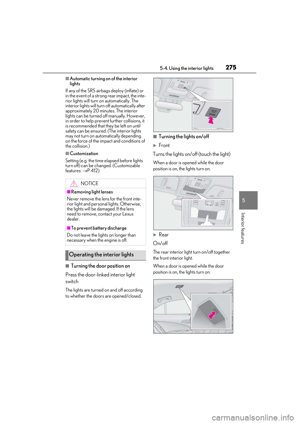
■Turning the door position on
Press the door-linked interior light
switch
The lights are turned on and off according
to whether the doors are opened/closed.
■Turning the lights on/off
Front
Turns the lights on/off (touch the light)
When a door is opened while the door
position is on, the lights turn on.
Rear
On/off
The rear interior light turn on/off together
the front interior light.
When a door is opened while the door
position is on, the lights turn on.
NOTICE
■Removing light lenses
Never remove the lens for the front inte-
rior light and personal lights. Otherwise,
the lights will be damaged. If the lens
need to remove, contact your Lexus
dealer.
■To prevent battery discharge
Do not leave the lights on longer than
necessary when the engine is off.
Operating the interior lights
Page 290 of 452

2905-6. Using the other interior features
the noise is reduced. If noise is reduced,
press and hold the power supply switch of
the wireless charger for 2 seconds. The fre-
quency of the wireless charger is changed
and noise may be reduced. When the fre-
quency is changed, the operation indicator
light will blink (orange) 2 times.
■Charging precautions
●If the electronic key cannot be detected
in the cabin, charging cannot be per-
formed. When a door is opened and
closed, charging may be temporarily sus-
pended.
●While charging, the wireless charger and
the portable device will become warm.
This is not a malfunction.
If a portable device becomes warm while
charging and charging stops due to the
protection function of the portable
device, wait until the portable device
cools down and charge it again.
■Sound generated during operation
When the power supply switch is turned on
or while a portable de vice is being identi-
fied, operation sounds may be heard. This is
not a malfunction.
■Cleaning the wireless charger
P.309
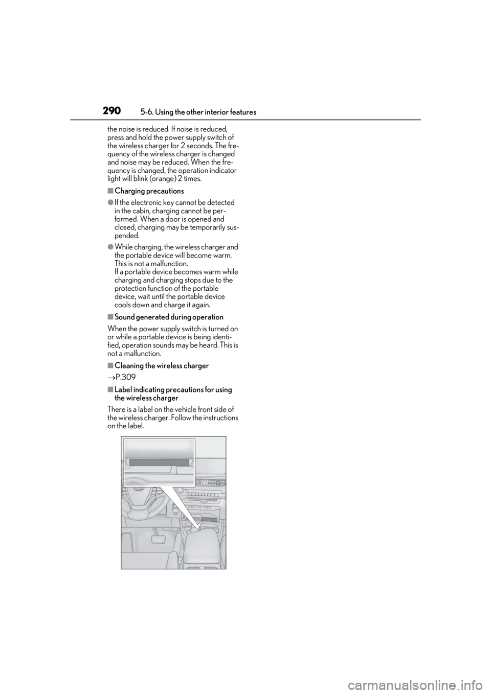
■Label indicating precautions for using
the wireless charger
There is a label on the vehicle front side of
the wireless charger. Follow the instructions
on the label.
Page 297 of 452

2975-6. Using the other interior features
5
Interior features
that garage doors, gates, or other
devices may operate. For this rea-
son, make sure that people and
objects are clear of the garage door
or other devices to prevent injury or
other potential harm.
It is recommended that a new bat-
tery be placed in the remote control
transmitter for more accurate pro-
gramming.
Garage door opener motors manu-
factured after 1995 may be
equipped with rolling code protec-
tion. If this is the case, you may need
a stepladder or other sturdy, safe
device to reach the “Learn” or
“Smart” button on the garage door
opener motor.
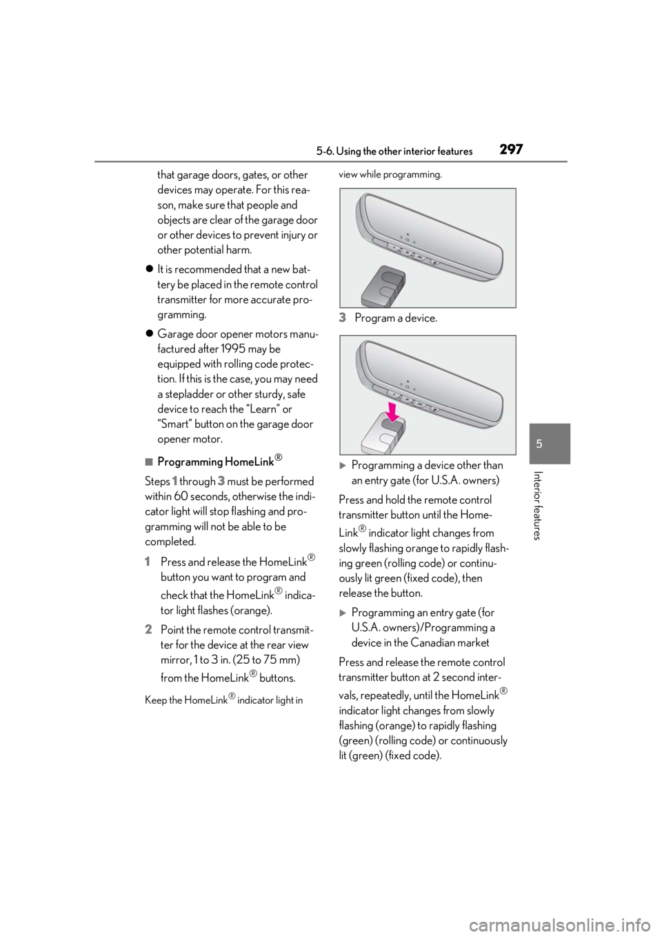
■Programming HomeLink®
Steps 1 through 3 must be performed
within 60 seconds, otherwise the indi-
cator light will stop flashing and pro-
gramming will not be able to be
completed.
1 Press and release the HomeLink
®
button you want to program and
check that the HomeLink
® indica-
tor light flashes (orange).
2 Point the remote control transmit-
ter for the device at the rear view
mirror, 1 to 3 in. (25 to 75 mm)
from the HomeLink
® buttons.
Keep the HomeLink® indicator light in view while programming.
3
Program a device.
Programming a device other than
an entry gate (for U.S.A. owners)
Press and hold the remote control
transmitter button until the Home-
Link
® indicator light changes from
slowly flashing orange to rapidly flash-
ing green (rolling code) or continu-
ously lit green (fixed code), then
release the button.
Programming an entry gate (for
U.S.A. owners)/Programming a
device in the Canadian market
Press and release the remote control
transmitter button at 2 second inter-
vals, repeatedly, until the HomeLink
®
indicator light changes from slowly
flashing (orange) to rapidly flashing
(green) (rolling code) or continuously
lit (green) (fixed code).
Page 300 of 452

3005-6. Using the other interior features
Press the appropriate HomeLink®
button. The HomeLink
® indicator light
should turn on.
The status of the opening and closing
of a garage door is shown by the indi-
cators.
Opening
Closing
This function is only available if the garage
door opener motor used is a compatible
device. (To check device compatibility,
refer to www.homelink.com.)
The indicators can operate within
approximately 820 ft. (250 m) of the
garage door. However, if there are
obstructions between the garage door
and the vehicle, such as houses and
trees, feedback signals from the
garage door may not be received. To recall the previous door operation
status, press and release either Home-
Link
® buttons and or
and simultaneously. The
last recorded status will be displayed
for 3 seconds.
Press and hold the 2 outside buttons
for 10 seconds until the HomeLink
®
indicator light changes from continu-
ously lit (orange) to rapidly flashing
(green).
If you sell your vehicle, be sure to erase the
programs stored in the HomeLink
® mem-
ory.
Operating HomeLink®
ColorStatus
Orange (flashing)Currently open- ing/closing
GreenOpening/closing has completed
Red (flashing)Feedback signals
cannot be received
A
B
Erasing the entire HomeLink®
memory (all three codes)
Page 331 of 452

3316-3. Do-it-yourself maintenance
6
Maintenance and care
■Routine tire inflation pressure checks
The tire pressure warning system does not
replace routine tire inflation pressure
checks. Make sure to check tire inflation
pressure as part of your routine of daily
vehicle checks.
■Tire inflation pressure
●It may take a few minutes to display the
tire inflation pressure after the engine
switch is turned to ON. It may also take a
few minutes to display the tire inflation
pressure after inflation pressure has been
adjusted.
●Tire inflation pressure changes with tem-
perature. The displayed values may also
be different from the values measured
using a tire pressure gauge.
■Situations in which the tire pressure
warning system may not operate prop-
erly
●In the following cases, the tire pressure
warning system may not operate prop-
erly.
• If non-genuine Lexus wheels are used.
• A tire has been replaced with a tire that is
not an OE (Original Equipment) tire.
• A tire has been replaced with a tire that is
not of the specified size.
• Tire chains etc. are equipped.
• An auxiliary-supported run-flat tire is equipped.
• If a window tint that affects the radio wave signals is installed.
• If there is a lot of snow or ice on the vehi-
cle, particularly around the wheels or
wheel housings.
• If the tire inflation pressure is extremely
higher than the specified level.
• If wheels without tire pressure warning valves and transmitters are used.
• If the ID code on the tire pressure warn- ing valves and transmitters is not regis-
tered in the tire pressure warning
computer.
●Performance may be affected in the fol-
lowing situations.
• Near a TV tower, electric power plant, gas station, radio stat ion, large display,
airport or other faci lity that generates
strong radio waves or electrical noise • When carrying a portable radio, cellular
phone, cordless phone or other wireless
communication device
If tire position information is not correctly
displayed due to the radio wave conditions,
the display may be corrected by driving and
changing the radio wave conditions.
●When the vehicle is parked, the time
taken for the warning to start or go off
could be extended.
●When tire inflation pr essure declines rap-
idly for example when a tire has burst, the
warning may not function.
■Warning performance of the tire pres-
sure warning system
The warning of the tire pressure warning
system will change in accordance with the
conditions under which it was initialized. For
this reason, the system may give a warning
even if the tire pressure does not reach a
low enough level, or if the pressure is higher
than the pressure that was adjusted to when
the system was initialized.