2019 LEXUS RC350 run flat
[x] Cancel search: run flatPage 282 of 390

2807-2. Steps to take in an emergency
RC350AWD_RC350_RC300AWD_RC30
0_OM_(U)_1810
4Tighten down the towing eyelet
securely using a wheel nut wrench
or hard metal bar.
5 Securely attach cables or chains to
the towing eyelet.
Take care not to damage the vehi-
cle body.
6 Enter the vehicle being towed and
start the engine.
If the engine does not start, turn the
engine switch to IGNITION ON
mode.
7 Shift the shift lever to N and release
the parking brake.
When the shift lever cannot be
shifted: P.129
■While towing
If the engine is not running, the power assist
for the brakes and steering will not function,
making steering and braking more difficult.
■Wheel nut wrench
Wheel nut wrench is installed in trunk.
( P.294)
Fluid leaks under the vehicle.
(Water dripping from the air condi-
tioning after use is normal.)
Flat-looking tires or uneven tire
wear
Engine coolant temperature gauge
continually points higher than nor-
mal.
Changes in exhaust sound
Excessive tire squeal when corner-
ing
Strange noises related to the sus-
pension system
Pinging or other noises related to
the engine
Engine missing, stumbling or run-
ning roughly
Appreciable loss of power
Vehicle pulls heavily to one side
when braking
If you think something is
wrong
If you notice any of the following
symptoms, your vehicle probably
needs adjustment or repair. Con-
tact your Lexus dealer as soon as
possible.
Visible symptoms
Audible symptoms
Operational symptoms
Page 299 of 390

2977-2. Steps to take in an emergency
RC350AWD_RC350_RC300AWD_RC30
0_OM_(U)_1810
7
When trouble arises
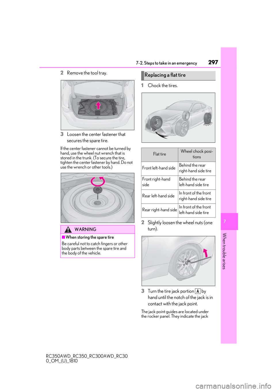
2Remove the tool tray.
3
Loosen the center fastener that
secures the spare tire.
If the center fastener cannot be turned by
hand, use the wheel nut wrench that is
stored in the trunk. (To secure the tire,
tighten the center fastener by hand. Do not
use the wrench or other tools.)
1Chock the tires.
2
Slightly loosen the wheel nuts (one
turn).
3
Turn the tire jack portion by
hand until the notch of the jack is in
contact with the jack point.
The jack point guides are located under
the rocker panel. They indicate the jack
WARNING
■When storing the spare tire
Be careful not to catch fingers or other
body parts between the spare tire and
the body of the vehicle.
Replacing a flat tire
Flat tireWheel chock posi- tions
Front left-hand sideBehind the rear
right-hand side tire
Front right-hand
sideBehind the rear
left-hand side tire
Rear left-hand sideIn front of the front
right-hand side tire
Rear right-hand sideIn front of the front
left-hand side tire
A
Page 324 of 390

3228-1. Specifications
RC350AWD_RC350_RC300AWD_RC30
0_OM_(U)_1810
*1: Minimum pedal clearance when depressed with a force of 112.4 lbf (500 N, 51.0 kgf)
while the engine is running.
*2: Parking brake pedal travel when depressed wi th a force of 67.4 lbf (300 N, 30.6 kgf)
Type A
Parking brake pedal travel*28 - 11 clicks
Fluid typeSAE J1703 or FMVSS No.116 DOT 3, or SAE
J1704 or FMVSS No.116 DOT 4 brake fluid
Steering
Free playLess than 1.2 in. (30 mm)
Tires and wheels
Tire size235/45R18 94Y, T155/70D17 110M (spare)
Tire inflation pressure (Rec-
ommended cold tire inflation
pressure)
Driving under normal conditions
Front: 35 psi (240 kPa, 2.4 kgf/cm
2 or bar)
Rear: 35 psi (240 kPa, 2.4 kgf/cm
2 or bar)
Spare: 60 psi (420 kPa, 4.2 kgf/cm
2 or bar)
Driving at high speeds (above 100 mph [160 km/h]) (in
countries where such speeds are permitted by law)
Add 3 psi (20 kPa, 0.2 kgf/cm
2 or bar) to the front tires, 6
psi (40 kPa, 0.4 kgf/cm
2 or bar) to the rear tires. Never
exceed the maximum co ld tire inflation pressure indicated
on the tire sidewall.
Wheel size18 8J, 17 4T (spare)
Wheel nut torque76 ft•lbf (103 N•m, 10.5 kgf•m)
Page 328 of 390

3268-1. Specifications
RC350AWD_RC350_RC300AWD_RC30
0_OM_(U)_1810
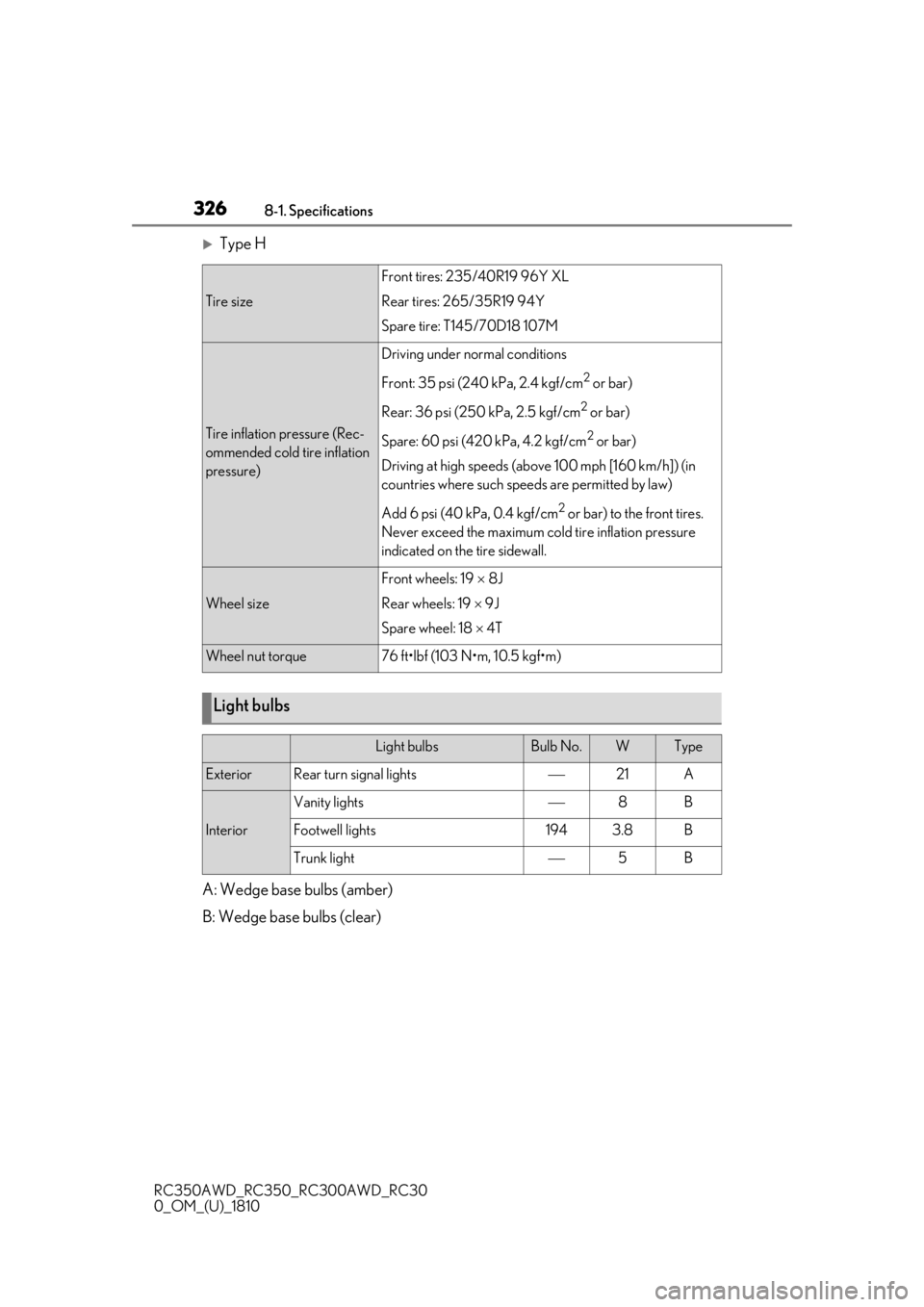
Type H
A: Wedge base bulbs (amber)
B: Wedge base bulbs (clear)
Tire size
Front tires: 235/40R19 96Y XL
Rear tires: 265/35R19 94Y
Spare tire: T145/70D18 107M
Tire inflation pressure (Rec-
ommended cold tire inflation
pressure)
Driving under normal conditions
Front: 35 psi (240 kPa, 2.4 kgf/cm
2 or bar)
Rear: 36 psi (250 kPa, 2.5 kgf/cm
2 or bar)
Spare: 60 psi (420 kPa, 4.2 kgf/cm
2 or bar)
Driving at high speeds (above 100 mph [160 km/h]) (in
countries where such speeds are permitted by law)
Add 6 psi (40 kPa, 0.4 kgf/cm
2 or bar) to the front tires.
Never exceed the maximum cold tire inflation pressure
indicated on the tire sidewall.
Wheel size
Front wheels: 19 8J
Rear wheels: 19 9J
Spare wheel: 18 4T
Wheel nut torque76 ft•lbf (103 N•m, 10.5 kgf•m)
Light bulbs
Light bulbsBulb No.WType
ExteriorRear turn signal lights21A
Interior
Vanity lights8B
Footwell lights1943.8B
Trunk light5B
Page 339 of 390

3378-1. Specifications
RC350AWD_RC350_RC300AWD_RC30
0_OM_(U)_1810
8
Vehicle specifications
*: Table 1 - Occupant loading and distribution for vehicle normal load for various desig-
nated seating capacities
Radial ply tire
A pneumatic tire in which the ply cords that extend
to the beads are laid at su bstantially 90 degrees to
the centerline of the tread
Reinforced tire
A tire designed to operat e at higher loads and at
higher inflation pressures than the corresponding
standard tire
Section width
The linear distance between the exteriors of the
sidewalls of an inflated tire, excluding elevations
due to labeling, decoration, or protective bands
SidewallThat portion of a tire between the tread and bead
Sidewall separationThe parting of the rubber compound from the cord
material in the sidewall
Snow tire
A tire that attains a traction index equal to or
greater than 110, compared to the ASTM E-1136
Standard Referenc e Test Tire, when using the snow
traction test as described in ASTM F-1805-00,
Standard Test Method fo r Single Wheel Driving
Traction in a Straight Line on Snow-and Ice-Cov-
ered Surfaces, and which is marked with an Alpine
Symbol ( ) on at least one sidewall
Test rimThe rim on which a tire is fitted for testing, and may
be any rim listed as appropriate for use with that tire
TreadThat portion of a tire that comes into contact with
the road
Tread ribA tread section running ci rcumferentially around a
tire
Tread separationPulling away of the tread from the tire carcass
Treadwear indicators (TWI)
The projections within the principal grooves
designed to give a visual indication of the degrees
of wear of the tread
Wheel-holding fixtureThe fixture used to hold the wheel and tire assembly
securely during testing
Tire related termMeaning
Page 384 of 390

382Alphabetical Index
RC350AWD_RC350_RC300AWD_RC30
0_OM_(U)_1810
Snow mode switch .................................... 130
“SOS” button .................................................. 53
Tilt and telescopic steering control switch 106
Tire pressure warning reset switch ..260
Trunk opener main switch ....................... 92
Trunk opener switch ................................... 90
VSC OFF switch .........................................193
Window lock switch ..................................... 111
Windshield wiper and washer switch .141
Windshield wiper de-icer switch ......209
T
Tachometer....................................................... 66 Rev indicator ................................................... 69
Rev peak ........................................................... 69
Tail lights Light switch .....................................................136
Replacing light bulbs................................ 270
Wattage.......................................................... 326
Theft deterrent system Alarm ..................................................................58
Engine immobilizer system ..................... 57
Theft prevention labels............................... 59
Tire inflation pressure Maintenance data...................................... 322
Tire inflation pressure display function .....
258
Warning light ............................................... 287
Tire information ............................................ 329 Glossary......................................................... 333
Size......................................................................331
Tire identification number .....................330
Uniform Tire Quality Grading............ 332
Tire infration pressure ...................................75
Tire pressure display .................................. 258
Tire pressure warning system Function ..........................................................258
Initializing .......................................................260
Installing tire pressure warning valves and transmitters ...................................... 259
Registering ID codes ................................. 261 Warning light ...............................................287
Tires Chains ...............................................................197
Checking .......................................................255
If you have a flat tire .................................. 294
Inflation pressure ..........................................261
Information ....................................................329
Replacing ....................................................... 294
Rotating tires ................................................ 257
Size .................................................................... 322
Snow tires ....................................................... 196
Spare tire ........................................................ 294
Tire inflation pressure display function......258
Tire pressure warning system ............ 258
Warning light ...............................................287
Tools.................................................................. 294
Top tether strap............................................... 50
Total load capacity ........................................316
Towing Dinghy towing ...............................................124
Emergency towing.................................... 277
Towing eyelet............................................... 279
Trailer towing .................................................124
TRAC (Traction Control) ..........................192
Traction Control (TRAC) ..........................192
Trailer towing .................................................. 124
Transmission Automatic transmission ........................... 128
Driving mode select switch ................... 190
M mode ............................................................. 131
Paddle shift switches ........................ 130, 131
Snow mode.................................................... 130
Trip meters ........................................................ 70
Trunk .................................................................... 89 Smart access system with push-button start ...................................................................90
Trunk features ................................................219
Trunk grip ...........................................................91
Trunk light ...........................................................91
Trunk opener main switch........................ 92
Trunk opener switch ...................................90
Page 390 of 390

388
RC350AWD_RC350_RC300AWD_RC30
0_OM_(U)_1810
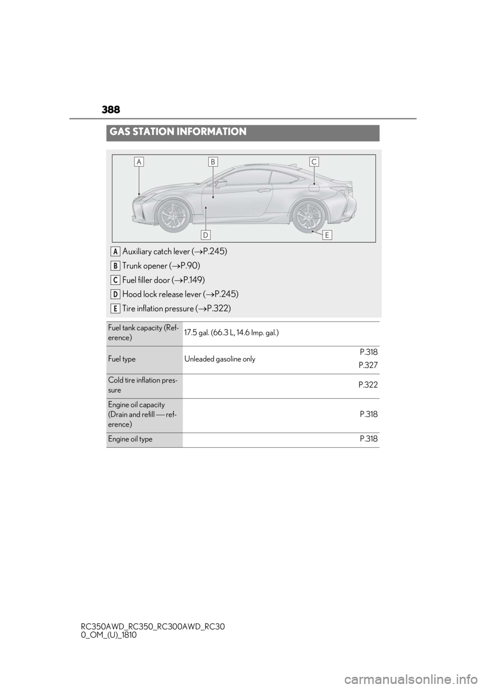
GAS STATION INFORMATION
Auxiliary catch lever (P.245)
Trunk opener ( P.90)
Fuel filler door ( P.149)
Hood lock release lever ( P.245)
Tire inflation pressure ( P.322)
Fuel tank capacity (Ref-
erence)17.5 gal. (66.3 L, 14.6 Imp. gal.)
Fuel typeUnleaded gasoline onlyP.318
P.327
Cold tire inflation pres-
sureP.322
Engine oil capacity
(Drain and refill ref-
erence)
P.318
Engine oil typeP.318
A
B
C
D
E