2019 Lexus LC500 warning lights
[x] Cancel search: warning lightsPage 74 of 432
742-1. Instrument cluster
2-1.Instrument cluster
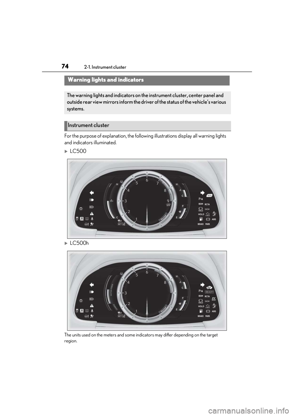
For the purpose of explanation, the following illustrations display all warning lights
and indicators illuminated.
LC500
LC500h
The units used on the meters and some indicators may differ depending on the target
region.
Warning lights and indicators
The warning lights and indicators on th e instrument cluster, center panel and
outside rear view mirrors inform the driver of the status of the vehicle’s various
systems.
Instrument cluster
Page 75 of 432
752-1. Instrument cluster
2
Vehicle status information and indicators
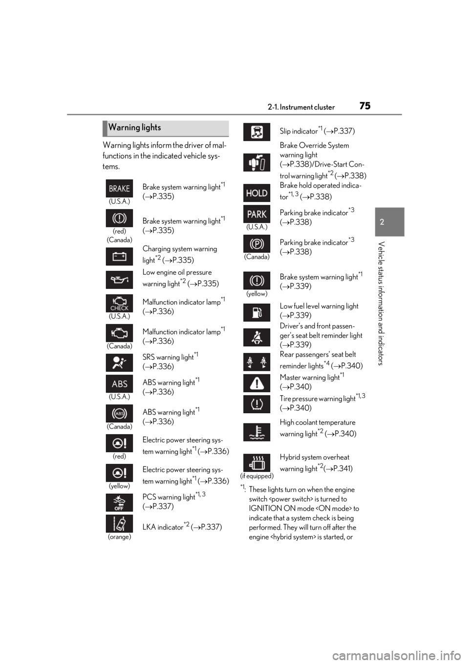
Warning lights inform the driver of mal-
functions in the indicated vehicle sys-
tems.
*1: These lights turn on when the engine switch
IGNITION ON mode
indicate that a system check is being
performed. They will turn off after the
engine
Warning lights
(U.S.A.)
Brake system warning light*1
( P.335)
(red)
(Canada)
Brake system warning light*1
( P.335)
Charging system warning
light
*2 ( P.335)
Low engine oil pressure
warning light
*2 ( P.335)
(U.S.A.)
Malfunction indicator lamp*1
( P.336)
(Canada)
Malfunction indicator lamp*1
( P.336)
SRS warning light
*1
( P.336)
(U.S.A.)
ABS warning light*1
( P.336)
(Canada)
ABS warning light*1
( P.336)
(red)
Electric power steering sys-
tem warning light
*1 ( P.336)
(yellow)
Electric power steering sys-
tem warning light
*1 ( P.336)
PCS warning light
*1, 3
( P.337)
(orange)
LKA indicator*2 ( P.337)
Slip indicator*1 ( P.337)
Brake Override System
warning light
( P.338)/Drive-Start Con-
trol warning light
*2 ( P.338)
Brake hold operated indica-
tor
*1, 3 ( P.338)
(U.S.A.)
Parking brake indicator*3
( P.338)
(Canada)
Parking brake indicator*3
( P.338)
(yellow)
Brake system warning light*1
( P.339)
Low fuel level warning light
( P.339)
Driver’s and front passen-
ger’s seat belt reminder light
( P.339)
Rear passengers’ seat belt
reminder lights
*4 ( P.340)
Master warning light
*1
( P.340)
Tire pressure warning light
*1, 3
( P.340)
High coolant temperature
warning light
*2 ( P.340)
(if equipped)
Hybrid system overheat
warning light
*2( P.341)
Page 89 of 432
892-1. Instrument cluster
2
Vehicle status information and indicators
• Audio system operation display
• Voice recognition display
• Instrument panel brightness adjust-ment display
■Ring position memory
Select to change the meter ring posi-
tion when the engine
started.
The position before the engine
tion can be selected.
■Accent color
Select to change the accent color on
the screen, such as the cursor color.
■Rev indicator
Select to set the rev indicator on/off.
When set to on, proceed to select the
engine speed at which the rev indicator
will be displayed.
■Rev peak
Select to set the rev peak on/off.
■Clock
Select to switch between 12-hour dis-
play and 24-hour display.
■Initialization
Select to reset the meter display set-
tings.
■Suspension of the settings display
In the following situations, operation of the
settings display will be temporarily sus-
pended.
●When a warning message appears on the
multi-information display
●When the vehicle begins to move
■Customization
The settings can be changed on of the
multi-information display.
●Settings of the driving assist systems
( P.391)
●Vehicle settings ( P.91, 283, 306, 308,
391)
Displays suggestions to the driver in
the following situations. For some sug-
gestions, a response to a displayed
suggestion can be selected. To select a
response, use the meter control
switches.
■Suggestion to turn on the head-
lights
If the headlight switch is in other than
or position, and the vehicle
speed is 3 mph (5 km/h) or higher for
a certain amount of time when the sur-
WARNING
■Cautions during setting up the dis-
play
As the engine
be running
the display, ensure that the vehicle is
parked in a place with adequate ventila-
tion. In a closed area such as a garage,
exhaust gases including harmful carbon
monoxide (CO) may collect and enter
the vehicle. This may lead to death or a
serious health hazard.
NOTICE
■While setting up the display
To prevent 12-volt battery discharge,
ensure that the engine is running
display features.
Suggestion function
Page 128 of 432
1283-4. Adjusting the steering wheel and mirrors
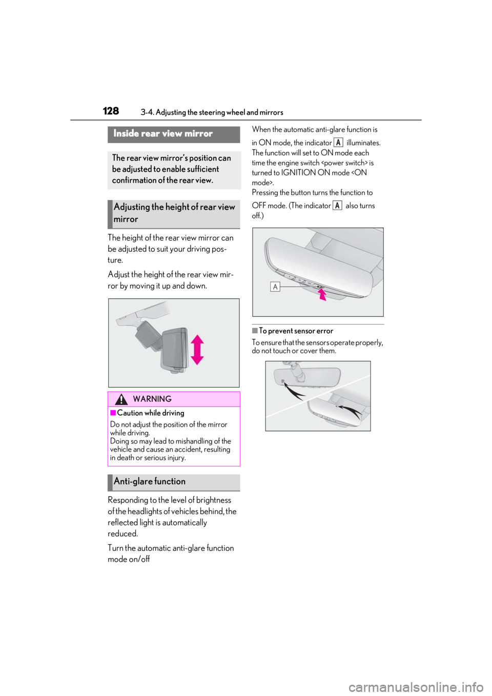
The height of the rear view mirror can
be adjusted to suit your driving pos-
ture.
Adjust the height of the rear view mir-
ror by moving it up and down.
Responding to the level of brightness
of the headlights of vehicles behind, the
reflected light is automatically
reduced.
Turn the automatic anti-glare function
mode on/off
When the automatic anti-glare function is
in ON mode, the indicator illuminates.
The function will set to ON mode each
time the engine switch
turned to IGNITION ON mode
Pressing the button turns the function to
OFF mode. (The indicator also turns
off.)
■To prevent sensor error
To ensure that the sensors operate properly,
do not touch or cover them.
Inside rear view mirror
The rear view mirror’s position can
be adjusted to enable sufficient
confirmation of the rear view.
Adjusting the height of rear view
mirror
WARNING
■Caution while driving
Do not adjust the position of the mirror
while driving.
Doing so may lead to mishandling of the
vehicle and cause an accident, resulting
in death or serious injury.
Anti-glare function
A
A
Page 167 of 432
1674-2. Driving procedures
4
Driving
shift only).
When vehicle speed increases
(upshift only).
When the accelerator pedal is firmly
depressed.
When it is necessary to protect the
transmission fluid temperature is
high or low, or other reasons.
Also, the gear will not shift when the
vehicle speed is low, even if an upshift
operation is performed.
■Downshifting restrictions warning
buzzer
To help ensure safety and driving perfor-
mance, downshifting operation may some-
times be restricted. In some circumstances,
downshifting may not be possible even
when the paddle shift switch is operated. (A
buzzer will sound twice.)
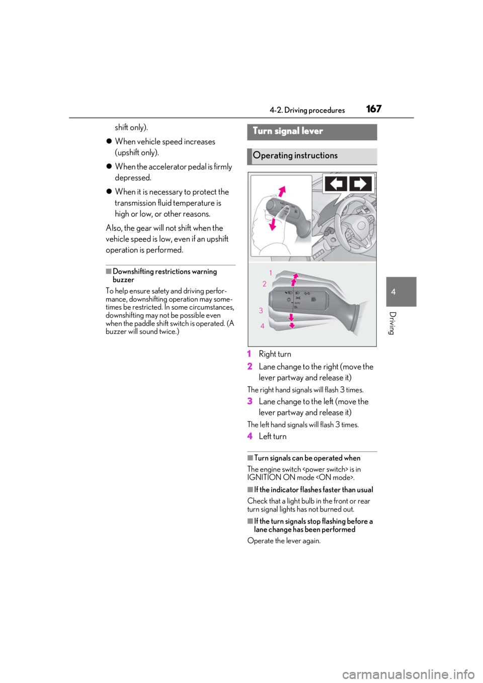
1 Right turn
2 Lane change to the right (move the
lever partway and release it)
The right hand signals will flash 3 times.
3Lane change to the left (move the
lever partway and release it)
The left hand signals will flash 3 times.
4Left turn
■Turn signals can be operated when
The engine switch
IGNITION ON mode
■If the indicator flashes faster than usual
Check that a light bulb in the front or rear
turn signal lights has not burned out.
■If the turn signals stop flashing before a
lane change has been performed
Operate the lever again.
Turn signal lever
Operating instructions
Page 176 of 432
1764-3. Operating the lights and wipers
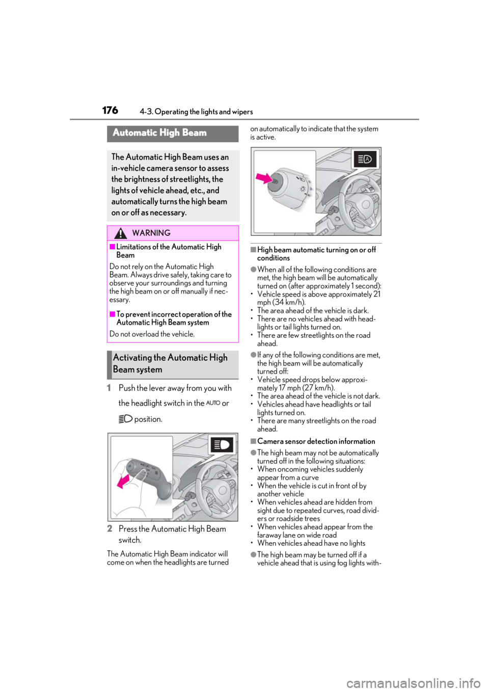
1Push the lever away from you with
the headlight switch in the or
position.
2 Press the Automatic High Beam
switch.
The Automatic High Beam indicator will
come on when the headlights are turned on automatically to indicate that the system
is active.
■High beam automatic turning on or off
conditions
●When all of the follo
wing conditions are
met, the high beam will be automatically
turned on (after approximately 1 second):
• Vehicle speed is above approximately 21 mph (34 km/h).
• The area ahead of the vehicle is dark.
• There are no vehicles ahead with head- lights or tail lights turned on.
• There are few streetlights on the road ahead.
●If any of the following conditions are met,
the high beam will be automatically
turned off:
• Vehicle speed drops below approxi- mately 17 mph (27 km/h).
• The area ahead of the vehicle is not dark.
• Vehicles ahead have headlights or tail
lights turned on.
• There are many streetlights on the road
ahead.
■Camera sensor dete ction information
●The high beam may not be automatically
turned off in the following situations:
• When oncoming vehicles suddenly appear from a curve
• When the vehicle is cut in front of by another vehicle
• When vehicles ahead are hidden from sight due to repeated curves, road divid-
ers or roadside trees
• When vehicles ahead appear from the faraway lane on wide road
• When vehicles ahead have no lights
●The high beam may be turned off if a
vehicle ahead that is using fog lights with-
Automatic High Beam
The Automatic High Beam uses an
in-vehicle camera sensor to assess
the brightness of streetlights, the
lights of vehicle ahead, etc., and
automatically turn s the high beam
on or off as necessary.
WARNING
■Limitations of the Automatic High
Beam
Do not rely on the Automatic High
Beam. Always drive sa fely, taking care to
observe your surroundings and turning
the high beam on or off manually if nec-
essary.
■To prevent incorrect operation of the
Automatic High Beam system
Do not overload the vehicle.
Activating the Automatic High
Beam system
Page 180 of 432
1804-3. Operating the lights and wipers
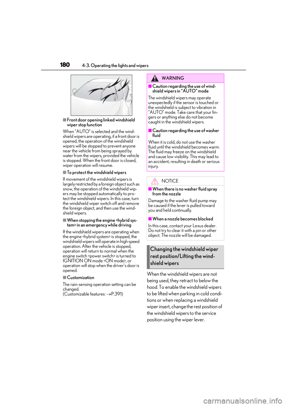
■Front door opening linked windshield
wiper stop function
When “AUTO” is selected and the wind-
shield wipers are operatin g, if a front door is
opened, the operation of the windshield
wipers will be stopped to prevent anyone
near the vehicle from being sprayed by
water from the wipers, provided the vehicle
is stopped. When the front door is closed,
wiper operation will resume.
■To protect the windshield wipers
If movement of the windshield wipers is
largely restricted by a foreign object such as
snow, the operation of the windshield wip-
ers may be stopped automatically to pro-
tect the windshield wipe rs. In this case, turn
the windshield wiper switch off and remove
the foreign object, and then use the wind-
shield wipers.
■When stopping the engine
If the windshield wipers are operating when
the engine
windshield wipers will operate in high speed
operation. After the vehicle is stopped,
operation will return to normal when the
engine switch
IGNITION ON mode
operation will stop when the driver’s door is
opened.
■Customization
The rain-sensing oper ation setting can be
changed.
(Customizable features: P.391)When the windshield wipers are not
being used, they retract to below the
hood. To enable the windshield wipers
to be lifted when parking in cold condi-
tions or when replacing a windshield
wiper insert, change the rest position of
the windshield wipers to the service
position using the wiper lever.
WARNING
■Caution regarding the use of wind-
shield wipers in “AUTO” mode
The windshield wipers may operate
unexpectedly if the sensor is touched or
the windshield is subj ect to vibration in
“AUTO” mode. Take care that your fin-
gers or anything else do not become
caught in the windshield wipers.
■Caution regarding the use of washer
fluid
When it is cold, do not use the washer
fluid until the windshield becomes warm.
The fluid may freeze on the windshield
and cause low visibility. This may lead to
an accident, resulting in death or serious
injury.
NOTICE
■When there is no washer fluid spray
from the nozzle
Damage to the washer fluid pump may
be caused if the lever is pulled toward
you and held continually.
■When a nozzle becomes blocked
In this case, contact your Lexus dealer.
Do not try to clear it with a pin or other
object. The nozzle will be damaged.
Changing the windshield wiper
rest position/Lifting the wind-
shield wipers
Page 188 of 432
1884-5. Using the driving support systems
WARNING
●If the part of the windshield in front of
the camera sensor is fogged up or
covered with condensation or ice, use
the windshield defogger to remove the
fog, condensation or ice. (P.249)
●If water droplets cannot be properly
removed from the area of the wind-
shield in front of the camera sensor by
the windshield wipers, replace the
wiper insert or wiper blade.
If the wiper inserts or wiper blades
need to be replaced, contact your
Lexus dealer.
●Do not attach window tinting to the
windshield.
●Replace the windshield if it is damaged
or cracked.
If the windshield needs to be replaced,
contact your Lexus dealer.
●Do not get the camera sensor wet.
●Do not allow bright lights to shine into
the camera sensor.
●Do not dirty or damage the camera
sensor.
When cleaning the inside of the wind-
shield, do not allow glass cleaner to
contact the lens. Also, do not touch the
lens.
If the lens is dirty or damaged, contact
your Lexus dealer.
●Do not subject the camera sensor to a
strong impact.
●Do not change the installation position
or direction of the camera sensor or
remove it.
●Do not disassemble the camera sen-
sor.
●Do not modify any components of the
vehicle around the camera sensor
(inside rear view mirror, etc.) or ceiling.
●Do not attach any accessories that
may obstruct the camera sensor to the
hood, front grille or front bumper.
Contact your Lexus dealer for details.
●If a surfboard or other long object is to
be mounted on the roof, make sure
that it will not obstruct the camera sen-
sor.
●Do not modify the headlights or other
lights.