Page 39 of 600

391-1. For safe use
1
For safety and security
GS450h_300h_OM_OM30F92E_(EE)
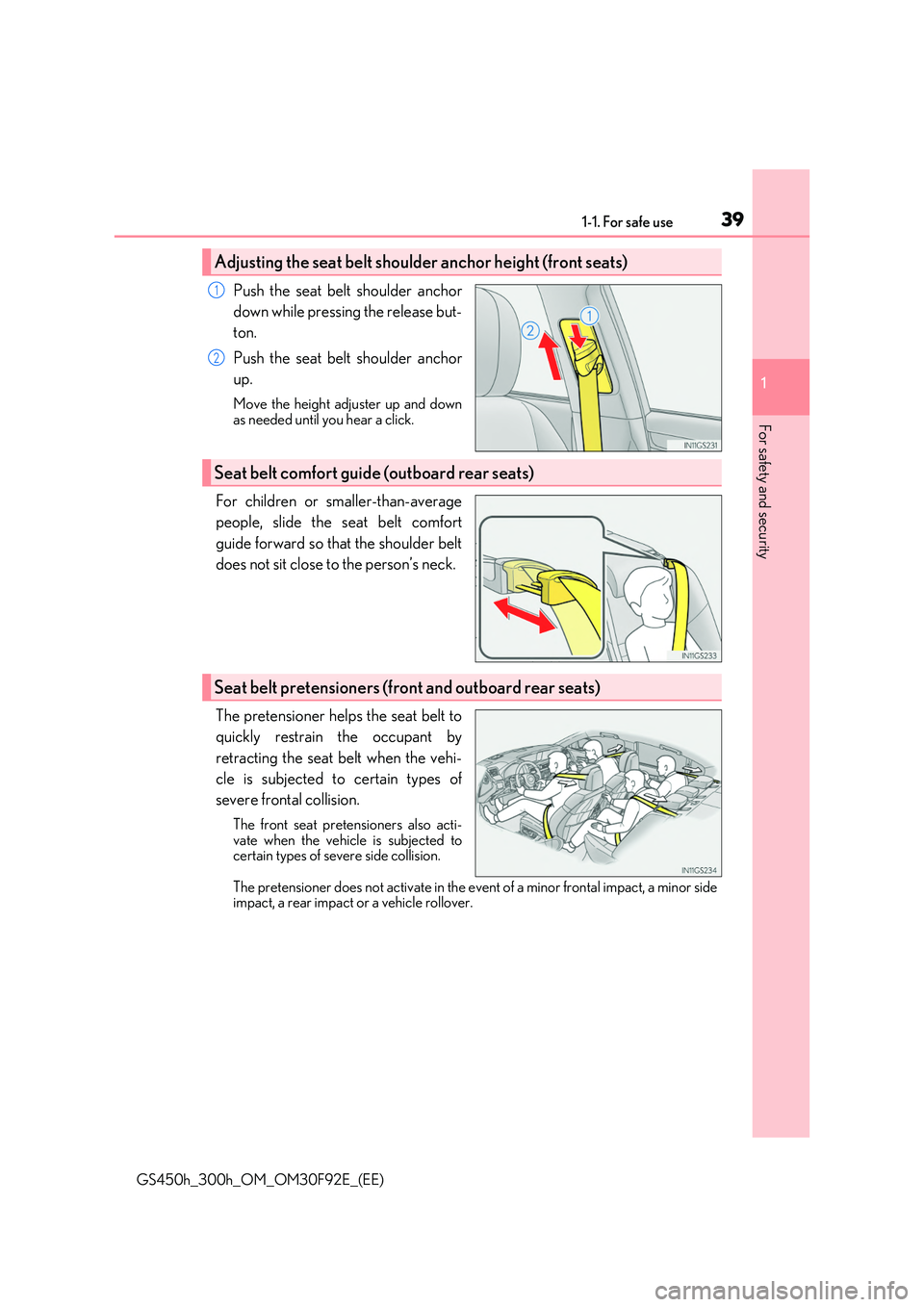
Push the seat belt shoulder anchor
down while pressing the release but-
ton.
Push the seat belt shoulder anchor
up.
Move the height adjuster up and down as needed until you hear a click.
For children or smaller-than-average
people, slide the seat belt comfort
guide forward so that the shoulder belt
does not sit close to the person’s neck.
The pretensioner helps the seat belt to
quickly restrain the occupant by
retracting the seat belt when the vehi-
cle is subjected to certain types of
severe frontal collision.
The front seat pretensioners also acti- vate when the vehicle is subjected tocertain types of severe side collision.
The pretensioner does not activate in the event of a minor frontal impact, a minor side impact, a rear impact or a vehicle rollover.
Adjusting the seat belt shoulder anchor height (front seats)
1
2
Seat belt comfort guide (outboard rear seats)
Seat belt pretensioners (front and outboard rear seats)
Page 60 of 600

601-1. For safe use
GS450h_300h_OM_OM30F92E_(EE)
Key of letters inserted in the above table:
U: Suitable for “universal” category child restraint systems approved for use in
this mass group.
UF: Suitable for forward-facing “universal” category child restraint systems
approved for use in this mass group.
L: Suitable for child restraint systems sh own in the child restraint system list.
X: Not suitable seat position for children in this mass group.
*1: Adjust the front seatback to the most upright position. Move the front seat to the rear-
most position.
If the head restraint interferes with your child restraint system, and the head restraint
can be removed, remove the head restraint.
If the passenger seat is equipped with a vertical height adjuster, it must be placed in
the upper most position.
Follow these procedures:
• For installing a baby seat with support base
If the baby seat interferes with the seatback when latching the baby seat into the support base, adjust the seatback rear ward until there is no interference. • For installing a forward-facing child seat
If there is gap between the child seat and the seatback, tilt the seatback rearward until good contact is achieved.If the seat belt shoulder anchor is ahead of the child seat belt guide, move the seat
cushion forward. • For installing a junior seatIf the child in your child restraint system is in a very upright position, adjust the seat-
back to the most comfortable position. If the seat belt shoulder anchor is ahead of the child seat belt guide, move the seat cushion forward.
*2: If the head restraint interferes with your child restraint system, and the head restraint
can be removed, remove the head restraint.
Page 175 of 600
175
3
3-3. Adjusting the seats
Operation of each component
GS450h_300h_OM_OM30F92E_(EE)
Front seats
Adjustment procedure
Seat position adjustment switch
Seatback angle adjustment switch
Seat cushion (front) angle adjust-
ment switch
Vertical height adjustment switch
Seatback upper angle adjustment
switch (if equipped)
Lumbar support adjustment switch
Pelvic support adjustment switch (if
equipped)
Seat cushion length adjustment
switch (if equipped) / ottoman
angle adjustment switch (if
equipped for front passenger’s
side)
Seatback side support adjustment
switch (if equipped)
1
2
3
4
5
6
7
8
9
Page 184 of 600

1843-3. Adjusting the seats
GS450h_300h_OM_OM30F92E_(EE)
Up
Pull the head restraints up.
Down
Push the head restraint down while pressing the lock release button.
■Removing the head restraints
■Installing the head restraints
Front seats
Rear seats
Rear seats
Lock release button
1
2
Pull the head restraint up while pressing the lockrelease button.
Front seats: If the head restraint touches the ceil- ing, making the removal difficult, change theseat height or angle. ( P. 175)
Outboard rear seats (v ehicles with rear sun- shade): If the rear sunshade is raised, lower itbefore removing the head restraint. ( P. 380)
Align the head restraint with the installation
holes and push it down to the lock position. Press and hold the lock release button whenlowering the head restraint.
Align the head restraint with the installation
holes and push it down to the lowest lock posi- tion while pressing the lock release button.
Lock release button
Lock release button
Lock release button
Page 185 of 600
1853-3. Adjusting the seats
3
Operation of each component
GS450h_300h_OM_OM30F92E_(EE)
■Adjusting the height of the head restraints
■Adjusting the rear seat head restraints
Always raise the head restraint one leve l from the stowed position when using.
Make sure that the head restraints are adjusted
so that the center of the head restraint is closest to the top of your ears.
WARNING
■Head restraint precautions
Observe the following precautions regarding th e head restraints. Failure to do so may result in death or serious injury.
●Use the head restraints designed for each respective seat.
●Adjust the head restraints to the correct position at all times.
●After adjusting the head restraints, push down on them and make sure they are
locked in position.
●Do not drive with the head restraints removed.
Page 188 of 600
1883-4. Adjusting the steering wheel and mirrors
GS450h_300h_OM_OM30F92E_(EE)
Inside rear view mirror
The height of the rear view mirror can be adjusted to suit your driving posture.
Adjust the height of the rear view mir-
ror by moving it up and down.
Responding to the level of brightness of the headlights of vehicles behind, the
reflected light is automatically reduced.
Changing automatic anti-glare func-
tion mode
ON/OFF
When the automatic anti-glare function is in ON mode, the indicator illuminates.The function will set to ON mode each
time the power switch is turned to ON mode.Pressing the button turns the function to
OFF mode. (The indicator also turns off.)
The rear view mirror’s position can be adjusted to enable sufficient confirma-
tion of the rear view.
Adjusting the height of rear view mirror
Anti-glare function
Indicator
Page 320 of 600

3204-5. Using the driving support systems
GS450h_300h_OM_OM30F92E_(EE)
■The Blind Spot Monitor function is operational when
●The BSM function is turned on.
●Vehicle speed is greater than approximately 16 km/h (10 mph).
■The Blind Spot Monitor function will detect a vehicle when
●A vehicle in an adjacent lane overtakes your vehicle.
●Another vehicle enters the detection area when it changes lanes.
■Conditions under which the Blind Spot Monitor function will not detect a vehicle
The Blind Spot Monitor function is not designed to detect the following types of vehicles and/or objects:
●Small motorcycles, bicycles, pedestrians etc.*
●Vehicles traveling in the opposite direction
●Guardrails, walls, signs, parked vehi cles and similar stationary objects*
●Following vehicles that are in the same lane*
●Vehicles driving 2 lanes across from your vehicle*
*: Depending on conditions, detection of a vehicle and/or object may occur.
■Conditions under which the Blind Spot Monitor function may not function correctly
●The Blind Spot Monitor function may not detect vehicles correctly in the following con-
ditions:
• During bad weather such as heavy rain, fog, snow etc. • When ice or mud etc. is attached to the rear bumper
• When driving on a road surface that is wet due to rain, standing water etc. • When there is a significant difference in speed between your vehicle and the vehiclethat enters the detection area
• When a vehicle is in the detection area from a stop and remains in the detection area as your vehicle accelerates• When driving up or down consecutive steep inclines, such as hills, a dip in the road
etc. • When multiple vehicles approach with only a small gap between each vehicle• When vehicle lanes are wide, and the vehicle in the next lane is too far away from
your vehicle • When the vehicle that enters the detection area is traveling at about the same speedas your vehicle
• When there is a significant difference in height between your vehicle and the vehicle that enters the detection area• Directly after the BSM function is turned on
• When your vehicle is towing a tra iler (vehicles with towing package)
●Instances of the Blind Spot Monitor function unnecessarily detecting a vehicle and/ or object may increase under the following conditions:
• When there is only a short distance between your vehicle and a guardrail, wall etc.
• When there is only a short distance between your vehicle and a following vehicle • When vehicle lanes are narrow and a vehicle driving 2 lanes across from your vehi-cle enters the detection area
• When items such as a bicycle carrier are installed on the rear of the vehicle
Page 500 of 600

5007-2. Steps to take in an emergency
GS450h_300h_OM_OM30F92E_(EE)
WARNING
■Using the tire jack
Observe the following precautions. Improper use of the tire jack may cause the vehicle to suddenly fall off the jack, leading
to death or serious injury.
●Do not use the tire jack for any purpose ot her than replacing tires or installing and removing tire chains.
●Only use the tire jack that comes with this vehicle for replacing a flat tire. Do not use it on other vehicles, and do no t use other tire jacks for replacing tires on this vehicle.
●Put the jack properly in its jack point.
●Do not put any part of your body under the vehicle while it is supported by the jack.
●Do not start the hybrid system or drive the vehicle while the vehicle is supported by
the jack.
●Do not raise the vehicle while someone is inside.
●When raising the vehicle, do not put an object on or under the jack.
●Do not raise the vehicle to a height greater than that required to replace the tire.
●Use a jack stand if it is necessary to get under the vehicle.
●When lowering the vehicle, make sure that there is no-one near the vehicle. If there
are people nearby, warn them vocally before lowering.