Page 206 of 555

4119
Features of your vehicle
✽ ✽NOTICE
• Do not place any accessories,
stickers or tint on the windshield.
• Have the windshield glass replaced by an authorized dealer.
• Do not remove or damage related parts of the High Beam Assist sys-
tem.
• Be careful that water doesn’t get into the High Beam Assist unit.
• Do not place objects on the dash- board that reflect light such as
mirrors, white paper, etc. The sys-
tem may not be able to function if
sunlight is reflected.
• At times, the High Beam Assist system may not operate due to sys-
tem limitations. Always check the
road conditions for your safety.
When the system does not operate
normally, manually change
between the high beam and low
beam.
Turn signals and lane change
signals
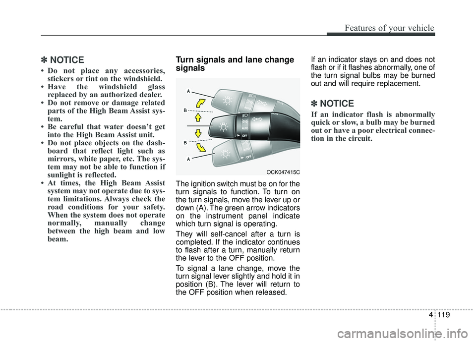
The ignition switch must be on for the
turn signals to function. To turn on
the turn signals, move the lever up or
down (A). The green arrow indicators
on the instrument panel indicate
which turn signal is operating.
They will self-cancel after a turn is
completed. If the indicator continues
to flash after a turn, manually return
the lever to the OFF position.
To signal a lane change, move the
turn signal lever slightly and hold it in
position (B). The lever will return to
the OFF position when released. If an indicator stays on and does not
flash or if it flashes abnormally, one of
the turn signal bulbs may be burned
out and will require replacement.
✽ ✽
NOTICE
If an indicator flash is abnormally
quick or slow, a bulb may be burned
out or have a poor electrical connec-
tion in the circuit.
OCK047415C
Page 218 of 555

4131
Features of your vehicle
If you want to defrost and defog the
front windshield, refer to “Windshield
defrosting and defogging” in this sec-
tion.
Rear window defroster
The defroster heats the window to
remove frost, fog and thin ice from
the rear window, while the engine is
running.
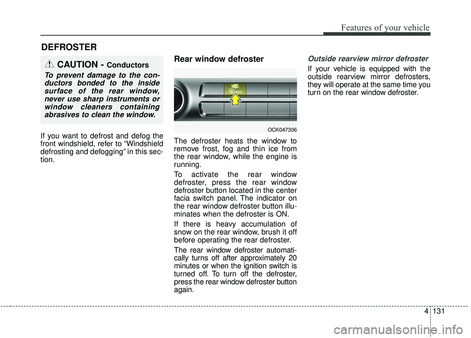
To activate the rear window
defroster, press the rear window
defroster button located in the center
facia switch panel. The indicator on
the rear window defroster button illu-
minates when the defroster is ON.
If there is heavy accumulation of
snow on the rear window, brush it off
before operating the rear defroster.
The rear window defroster automati-
cally turns off after approximately 20
minutes or when the ignition switch is
turned off. To turn off the defroster,
press the rear window defroster button
again.
Outside rearview mirror defroster
If your vehicle is equipped with the
outside rearview mirror defrosters,
they will operate at the same time you
turn on the rear window defroster.
DEFROSTER
CAUTION - Conductors
To prevent damage to the con-ductors bonded to the insidesurface of the rear window,never use sharp instruments orwindow cleaners containingabrasives to clean the window.
OCK047306
Page 221 of 555
Features of your vehicle
134
4
✽ ✽
NOTICE
Never place anything over the sensor
located on the instrument panel to
ensure better control of the heating
and cooling system.
OCK047427L
Page 224 of 555
4137
Features of your vehicle
Defrost-Level
Most of the air flow is directed to the
windshield with a small amount of air
directed to the side window defrosters.Instrument panel vents
The outlet vents can be opened or
closed separately using the thumb-
wheel (if equipped).
Also, you can adjust the direction of
air delivery from these vents using
the vent control lever as shown.
Temperature control
The temperature will increase to the
maximum (HI) by turning the knob to
the extreme right.
OCK047310OCK048321NOCK047311
OCK047323
■ Rear seat
■ Front seat
Page 367 of 555

Driving your vehicle
114
5
LKA system operation
To activate/deactivate the LKA sys-
tem:
With the ignition switch in the ON
position, press the LKA system but-
ton located on the instrument panel
on the lower left hand side of the
driver.
The indicator in the cluster display
will initially illuminate white.
When the indicator (white) activated
in the previous ignition cycle, the
system turns on without any control. If you press the LKA system button
again, the indicator on the cluster
display will go off.
The color of indicator will change
depend on the condition of LKA sys-
tem.
- White : Sensor does not detect the
lane marker or vehicle
speed is less than 64 km/h
(40 mph).
- Green : S ensor detects the lane
marker and system is able
to control the steering.
LKA system activation
To see the LKA system screen on the LCD display in the cluster, Tab
to the Assist mode ( ).
For further details, refer to "User Setting Mode" in chapter 4.
After LKA system is activated, if both lane markers are detected, vehicle
speed is over 64 km/h (40 mph) and
all the activation conditions are sat-
isfied, a green steering wheel indi-
cator will illuminate and the steering
wheel will be controlled.
OCK057038N
WARNING
The Lane Keeping Assist sys-
tem is a system to help prevent
the driver from leaving the lane.
However, the driver should not
solely rely on the system but
always check the road condi-
tions when driving.
Page 488 of 555

757
Maintenance
3. Pull the suspected fuse straightout. Use the removal tool provided
on the engine compartment fuse
panel cover.
4. Check the removed fuse; replace it if it is blown.
Spare fuses are provided in theengine compartment fuse panel.
5. Push in a new fuse of the same rating, and make sure it fits tightly
in the clips.
If it fits loosely, consult an authorized
Kia dealer.
If you do not have a spare, use a fuse of the same rating from a circuityou may not need for operating thevehicle, such as the power outletfuse.
If the head lamp, turn signal lamp,
stop signal lamp, fog lamp, DRL, tail
lamp, HMSL do not work and the
fuses are OK, check the fuse panel
in the engine compartment. If a fuse
is blown, it must be replaced.
✽ ✽ NOTICE
If the headlamp, fog lamp, turn sig-
nal lamp, or tail lamp malfunction
even without any problem to the
lamps, have the vehicle checked by
an authorized Kia dealer for assis-
tance.
Fuse switch
Always set the fuse switch to the ON
position before using the vehicle.
If you move the switch to the OFF
position, some items such as audio
and digital clock must be reset and
transmitter (or smart key) may not
work properly. When the switch is
Off, the caution indicator will be dis-
played on the instrument cluster.
Always place the fuse switch in the
ON position while driving the vehicle.
If the switch is located in the “OFF”
position, a caution indicator will be
displayed in the cluster.
OCK077033
OCK077034
Page 494 of 555
763
Maintenance
Fuse NameFuse ratingCircuit Protected
MULTI MEDIA 125ALow DC-DC Converter (Audio)
AIR BAG15ASRS (Supplemental Restraint System) Control Module
INTERIOR LAMP10AOverhead Console Lamp, Center Room Lamp, Room Lamp, Vanity Lamp Switch Left Handle side/Right
Handle side, Luggage Lamp Left Handle side/Right Handle side, Glove Box Lamp, Driver/Passenger Door
Mood Lamp, Driver/Passenger Door Lamp, Driver/Passenger Foot Lamp
STOP LAMP10AIBU, Stop Lamp Switch
CLUSTER10AInstrument Cluster, Head-Up Display
E-SHIFTER 210AElectronic Auto Transmission Shift Lever (IG1)
IBU 410AIBU (IG1)
MULTI MEDIA 310AInstrument Cluster, Head-Up Display, Air Conditioner Switch
MULTI MEDIA 215AAudio
MEMORY 110AAir Conditioner Control Module, Air Conditioner Switch, Security Indicator, Head-Up Display
IBU 310AIBU (B+)
Instrument panel (Driver’s side fuse panel)
Page 499 of 555
Maintenance
68
7
Fuse NameFuse ratingCircuit Protected
ALT175A
200AAlternator, Multi Fuse
- COOLING FAN 1 / B+5 / B+4 / B+3 / OPCU / ESC1 / ESC2 / BLOWER / POWER TAIL GATE
COOLING FAN 2100A[BLDC (Brushless Direct Current) Motor] Cooling Fan Controller
START30AStart Relay
COOLING FAN 180A[BLDC (Brushless Direct Current) Motor] Cooling Fan Controller
B+550AInstrument Panel Junction Block
(Fuse - STOP LAMP / Leak Current Autocut Device Fuse / INTERIOR LAMP)
B+450AInstrument Panel Junction Block
(Fuse - DOOR LOCK / POWER HANDLE / SUNROOF / P/SEAT (DRV) / P/SEAT (PASS))
B+350AInstrument Panel Junction Block
(Fuse - S/HEATER DRV/PASS / TAIL GATE / MODULE9 / P/WINDOW RH / P/WINDOW LH)
OPCU50AElectric Oil Pump Inverter
ESC 140AESC (Electronic Stability Control) Control Module
ESC 240AESC (Electronic Stability Control) Control Module, Multipurpose Check Connector
BLOWER40ABlower Relay
POWER TAIL GATE30APower Tail Gate Module
Engine room compartment fuse panel