Page 217 of 455
Features of your vehicle
80
4
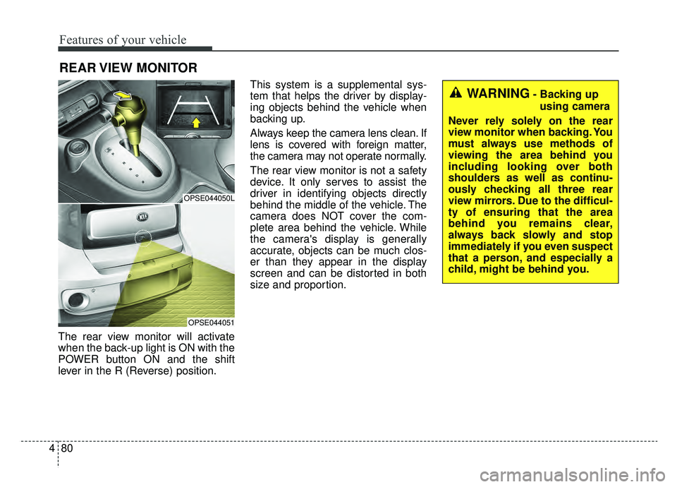
The rear view monitor will activate
when the back-up light is ON with the
POWER button ON and the shift
lever in the R (Reverse) position. This system is a supplemental sys-
tem that helps the driver by display-
ing objects behind the vehicle when
backing up.
Always keep the camera lens clean. If
lens is covered with foreign matter,
the camera may not operate normally.
The rear view monitor is not a safety
device. It only serves to assist the
driver in identifying objects directly
behind the middle of the vehicle. The
camera does NOT cover the com-
plete area behind the vehicle. While
the camera's display is generally
accurate, objects can be much clos-
er than they appear in the display
screen and can be distorted in both
size and proportion.
REAR VIEW MONITOR
OPSE044050L
OPSE044051
WARNING- Backing up
using camera
Never rely solely on the rear
view monitor when backing. You
must always use methods of
viewing the area behind you
including looking over both
shoulders as well as continu-
ously checking all three rear
view mirrors. Due to the difficul-
ty of ensuring that the area
behind you remains clear,
always back slowly and stop
immediately if you even suspect
that a person, and especially a
child, might be behind you.
Page 231 of 455
Features of your vehicle
94
4
AUTOMATIC CLIMATE CONTROL SYSTEM
OPSE045310N/OPSE044162N
1. Fan speed control button
2. Front windshield defroster button
3. Rear windshield defroster button
4. Temperature control knob/button
5. AUTO (automatic control) button
6. OFF button
7. HEAT button
8. Air conditioning button
9. Climate control information screen
selection button
10. Mode selection button
11. Driver Only button
12. Air intake control button
13. Climate control timer
14. Climate control display
■ ■ Type A
■ ■Type B
Page 232 of 455
495
Features of your vehicle
Automatic heating and air
conditioning
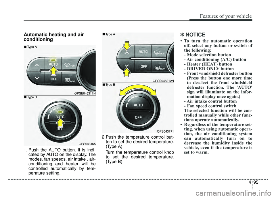
1. Push the AUTO button. It is indi-cated by AUTO on the display. The
modes, fan speeds, air intake , air-
conditioning and heater will be
controlled automatically by tem-
perature setting. 2.Push the temperature control but-
ton to set the desired temperature.
(Type A)
Turn the temperature control knob
to set the desired temperature.
(Type B)
✽ ✽ NOTICE
• To turn the automatic operation
off, select any button or switch of
the following:
- Mode selection button
- Air conditioning (A/C) button
- Heater (HEAT) button
- DRIVER ONLY button
- Front windshield defroster button(Press the button one more time
to deselect the front windshield
defroster function. The 'AUTO'
sign will illuminate on the infor-
mation display once again.)
- Air intake control button
- Fan speed control switch
The selected function will be con-
trolled manually while other func-
tions operate automatically.
• Regardless of the temperature set- ting, when using automatic opera-
tion, the air conditioning system
can automatically turn on to
decrease the humidity inside the
vehicle, even if the temperature is
set to warm.
OPSE045311N
OPS043165
■ Type B
■Type A
OPSE045312N
OPS043171
■Type B
■Type A
Page 237 of 455
Features of your vehicle
100
4
The temperature will decrease to the
minimum (62°F(17°C)) by pushing
the button ( ).
When pushing the button, the tem-
perature will increase or decrease by
0.5°C/1°F. When set to the lowest
temperature setting, the air condi-
tioning will operate continuously.
B
The temperature will increase to the
maximum (90°F(32°C)) by turning
the knob to the right extreme.
The temperature will decrease to the
minimum (62°F(17°C)) by turning the
knob to the left extreme.
When turning the knob, the tempera-
ture will increase or decrease by
0.5°C/1°F. When set to the lowest
temperature setting, the air condi-
tioning will operate continuously. Temperature scale conversion
If the battery has been discharged or
disconnected, the temperature mode
display will reset to Centigrade.
This is normal condition. You can
switch the temperature scale as fol-
lows;
While pressing the AUTO button,
press the OFF button for 3 seconds
or more. The temperature scale will
change from Centigrade to
Fahrenheit, or from Fahrenheit to
Centigrade.
The temperature unit (from °C to °F
or from °F to °C) can be changed by
using the “User Settings” mode of the
LCD display.
❈
If you change the temperature
unit, the temperature unit on the
instrument cluster is changed as
well.Air intake control
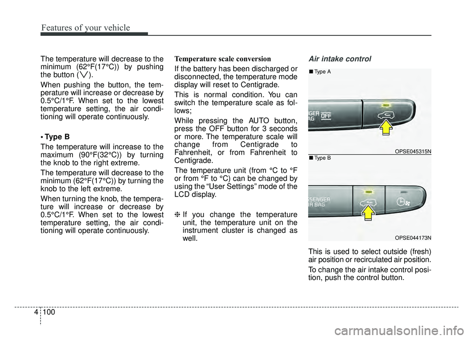
This is used to select outside (fresh)
air position or recirculated air position.
To change the air intake control posi-
tion, push the control button.
OPSE045315N
OPSE044173N
■Type B
■Type A
Page 242 of 455
4105
Features of your vehicle
Reserved Climate Control Button(if equipped)
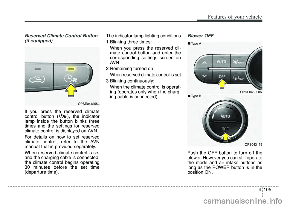
If you press the reserved climate
control button ( ), the indicator
lamp inside the button blinks three
times and the settings for reserved
climate control is displayed on AVN.
For details on how to set reserved
climate control, refer to the AVN
manual that is provided separately.
When reserved climate control is set
and the charging cable is connected,
the climate control begins operating
30 minutes before the set time
(departure time). The indicator lamp lighting conditions
1.Blinking three times:
When you press the reserved cli-
mate control button and enter the
corresponding settings screen on
AVN
2.Remaining turned on: When reserved climate control is set
3.Blinking continuously: When the climate control is operat-
ing (operates only when the charg-
ing cable is connected)
Blower OFF
Push the OFF button to turn off the
blower. However you can still operate
the mode and air intake buttons as
long as the POWER button is in the
position ON.
OPSE044255L
OPSE045320N
OPS043179
■ Type B
■Type A
Page 286 of 455
57
Driving your vehicle
Starting the vehicle
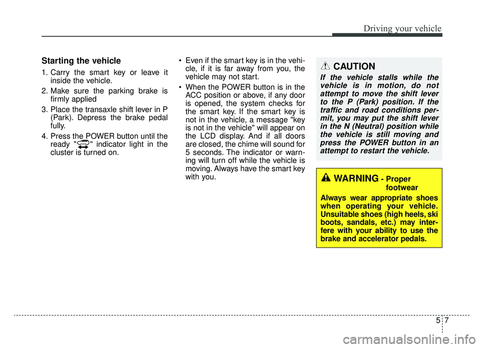
1. Carry the smart key or leave itinside the vehicle.
2. Make sure the parking brake is firmly applied
3. Place the transaxle shift lever in P (Park). Depress the brake pedal
fully.
4. Press the POWER button until the ready " " indicator light in the
cluster is turned on. Even if the smart key is in the vehi-
cle, if it is far away from you, the
vehicle may not start.
When the POWER button is in the ACC position or above, if any door
is opened, the system checks for
the smart key. If the smart key is
not in the vehicle, a message "key
is not in the vehicle" will appear on
the LCD display. And if all doors
are closed, the chime will sound for
5 seconds. The indicator or warn-
ing will turn off while the vehicle is
moving. Always have the smart key
with you.CAUTION
If the vehicle stalls while thevehicle is in motion, do notattempt to move the shift leverto the P (Park) position. If thetraffic and road conditions per-mit, you may put the shift leverin the N (Neutral) position whilethe vehicle is still moving andpress the POWER button in anattempt to restart the vehicle.
WARNING- Proper
footwear
Always wear appropriate shoes
when operating your vehicle.
Unsuitable shoes (high heels, ski
boots, sandals, etc.) may inter-
fere with your ability to use the
brake and accelerator pedals.
Page 291 of 455
Driving your vehicle
12
5
Reduction gear operation
When stopped on an incline, do not
hold the vehicle with the motor
power. Use the service brake or the
parking brake.
Reduction gear ranges
The indicator in the instrument clus-
ter displays the shift lever position
when the POWER button is in the
ON position.
P (Park)
Always come to a complete stop
before shifting into P (Park). This
position locks the gear and prevents
the drive wheels from rotating.
Shifting into P (Park) while the vehi-
cle is in motion will cause the drive
wheels to lock which will cause you
to lose control of the vehicle.
WARNING- Leaving the
vehicle
Before leaving the driver’s seat,
always make sure the shift lever
is in the P (Park) position; then
set the parking brake fully and
shut the vehicle off. Do not use
the P position in place of the
parking brake. Always make
sure the shift lever is latched in
the P position and set the park-
ing brake fully. Unexpected and
sudden vehicle movement can
occur if these precautions are
not followed.
CAUTION- Reduction gear
To avoid damage to your reduc-tion gear, do not accelerate thevehicle in R (Reverse) or anyforward gear position with thebrakes on. The reduction gearmay be damaged if you shiftinto P (Park) while the vehicle isin motion.
Page 349 of 455
What to do in an emergency
16
6
0. Speed restriction label
1. Sealant bottle and label with
speed restriction
2. Filling hose from sealant bottle to wheel
3. Connectors and cable for the power outlet direct connection 4. Holder for the sealant bottle
5. Compressor
6. On/off switch
7. Pressure gauge for displaying the
tire inflation pressure
8. Screw cap for reducing tire infla- tion pressure 9. Hose to connect compressor and
sealant bottle or compressor and
wheel
Connectors, cable and connection
hose are stored in the compressor
housing.
Strictly follow the specified
sequence, otherwise the sealant
may escape under high pressure.
Components of the Tire Mobility Kit
OAM060015L
WARNING- Expired sealant
Do not use the Tire sealant after
the sealant has expired (i.e.
pasted the expiration date on
the sealant container). This can
increase the risk of tire failure.
WARNING - Sealant
• Keep out of reach of children.
Avoid contact with eyes.
Do not swallow.