Page 530 of 611

Maintenance
56
8
FUSES
❈ Left side : Normal , Right side : Blown
A vehicle’s electrical system is pro-
tected from electrical overload dam-
age by fuses.
This vehicle has 2 (or 3) fuse panels,
one located in the driver’s side panel
bolster, the other in the engine com-
partment near the battery.
If any of your vehicle’s lights, acces-
sories, or controls do not work, check
the appropriate circuit fuse. If a fuse
has blown, the element inside the
fuse will melt.
If the electrical system does not
work, first check the driver’s side
fuse panel.
Always replace a blown fuse with
one of the same rating.
If the replacement fuse blows, this
indicates an electrical problem. Avoid
using the system involved and imme-
diately consult an authorized Kia
dealer.
Three kinds of fuses are used: blade
type for lower amperage rating, car-tridge type, and multi fuse for higheramperage ratings.
Do not arbitrarily modify or add-on electric wiring to the vehicle.
WARNING- Fuse replace-
ment
Never replace a fuse with any- thing but another fuse of the
same rating.
A higher capacity fuse could cause damage and possibly a
fire.
Never install a wire or alu- minum foil instead of the
proper fuse - even as a tem-
porary repair. It may cause
extensive wiring damage and
a possible fire.
CAUTION
Do not use a screwdriver or anyother metal object to removefuses because it may cause ashort circuit and damage thesystem.
OJF075021
■
Blade type
■ Cartridge type
■ Multi fuse
■ BFT
Page 549 of 611
875
Maintenance
Fuse NameFuse ratingCircuit Protected
FUSE
ACTIVE
HYDRAULIC BOOTER 230AIntegrated Brake Actuation Unit
INVERTER30AAC Inverter Module
POWER
OUTLET 140APower Outlet Relay
B/UP LAMP10AElectro Chromic Mirror, Back-Up Lamp LH/RH
ECU 310AECM (Engine Control Module)
HPCU 215AHPCU (Hybrid Power Control Unit), Clutch Actuator (HEV)
ACTIVE
HYDRAULIC BOOTER 310AIntegrated Brake Actuation Unit, Multipurpose Check Connector
DCT 415ADCT (Dual clutch transmission) Shift Lever, TCM (Transmission Control Module), Inhibitor
Switch
SENSOR 310AFuel Pump Relay, Oil Control Valve #1/#2 (Intake/Exhaust), Camshaft Position Sensor #1/#2
(Intake/Exhaust)
BATTERY C/FAN15ABattery C/Fan Relay
HORN20AHorn Relay
SENSOR 210APurge Control Solenoid Valve, Cooling Fan Relay, Canister Close Valve, Mass Air Flow Sensor
ECU 120AECM (Engine Control Module)
Page 550 of 611
Maintenance
76
8
Fuse NameFuse ratingCircuit Protected
FUSE
SENSOR 115AOxygen Sensor (Up), Oxygen Sensor (Down)
IGN COIL20AIgnition Coil #1/#2/#3/#4
ECU 215AECM (Engine Control Module)
B/ALARM HORN10ABurglar Alarm Horn Relay
Page 553 of 611
879
Maintenance
Fuse NameFuse ratingCircuit Protected
FUSE
ACTIVE
HYDRAULIC BOOTER 230AIntegrated Brake Actuation Unit
INVERTER30AAC Inverter Module
POWER
OUTLET 140APower Outlet Relay
B/UP LAMP10AElectro Chromic Mirror, Back-Up Lamp LH/RH
ECU 310AECM (Engine Control Module)
HPCU 215AHPCU (Hybrid Power Control Unit), Clutch Actuator (PHEV)
ACTIVE
HYDRAULIC BOOTER 310AIntegrated Brake Actuation Unit, Multipurpose Check Connector
DCT 415ADCT(Dual clutch transmission) Shift Lever, TCM (Transmission Control Module), Inhibitor
Switch
SENSOR 310AFuel Pump Relay, Oil Control Valve #1/#2 (Intake/Exhaust), Camshaft Position Sensor #1/#2
(Intake/Exhaust)
BATTERY C/FAN15ABattery C/Fan Relay
HORN20AHorn Relay
SENSOR 210APurge Control Solenoid Valve, Cooling Fan Relay, Canister Close Valve, Mass Air Flow Sensor
ECU 120AECM (Engine Control Module)
Page 554 of 611
Maintenance
80
8
Fuse NameFuse ratingCircuit Protected
FUSE
SENSOR 115AOxygen Sensor (Up), Oxygen Sensor (Down)
IGN COIL20AIgnition Coil #1/#2/#3/#4
ECU 215AECM (Engine Control Module)
B/ALARM HORN10ABurglar Alarm Horn Relay
Page 573 of 611

899
Maintenance
High-pressure washing
When using high-pressure wash-ers, make sure to maintain suffi-
cient distance from the vehicle.
Insufficient clearance or excessive
pressure can lead to component
damage or water penetration.
Do not spray the camera, sensors or its surrounding area directly with
a high pressure washer. Shock
applied from high pressure water
may cause the device to not oper-
ate normally.
Do not bring the nozzle tip close to boots (rubber or plastic covers) or
connectors as they may be dam-
aged if they come into contact with
high pressure water. Waxing
Wax the vehicle when water will no
longer bead on the paint.
Always wash and dry the vehicle
before waxing. Use a good quality
liquid or paste wax, and follow the
manufacturer’s instructions. Wax all
metal trim to protect it and to main-
tain its luster.
Removing oil, tar, and similar materi-
als with a spot remover will usually
strip the wax from the finish. Be sure
to re-wax these areas even if the rest
of the vehicle does not yet need wax-
ing.
Do not apply wax on embossed
unpainted unit, as it may tarnish the
unit.
ODEP077071L
CAUTION - Wet engine
Water washing in the engine
compartment including highpressure water washing maycause the failure of electricalcircuits located in the enginecompartment.
Never allow water or other liq- uids to come in contact withelectrical/electronic compo-nents inside the vehicle asthis may damage them.
(Continued)
(Continued) To prevent damage to the charging door, make sure toclose and lock the vehicledoors when washing (high-pressure washing, automaticcar washing, etc.) the vehicle.
Page 590 of 611

97
Specifications, Consumer information, Reporting safety defects
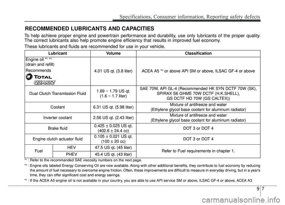
RECOMMENDED LUBRICANTS AND CAPACITIES
To help achieve proper engine and powertrain performance and durability, use only lubricants of the proper quality.
The correct lubricants also help promote engine efficiency that results in improved fuel economy.
These lubricants and fluids are recommended for use in your vehicle.
*1: Refer to the recommended SAE viscosity numbers on the next page.
*2: Engine oils labeled Energy Conserving Oil are now available. Along with other additional benefits, they contribute to fuel economy by reducing the amount of fuel necessary to overcome engine friction. Often, these improvements are difficult to measure in everyday driving, but in a year’s
time, they can offer significant cost and energy savings.
*
3: If the ACEA A5 engine oil is not available in your country, you are able to use API service SM or above, ILSAC GF-4 or above, ACEA A3
Lubricant VolumeClassification
Engine oil *1*2
(drain and refill)
Recommends
4.01 US qt. (3.8 liter)ACEA A5 *3or above API SM or above, ILSAC GF-4 or above
Dual Clutch Transmission Fluid1.69 ~ 1.79 US qt. (1.6 ~ 1.7 liter)SAE 70W, API GL-4 (Recommended HK SYN DCTF 70W (SK), SPIRAX S6 GHME 70W DCTF (H.K.SHELL), GS DCTF HD 70W (GS CALTEX))
Coolant6.31 US qt. (5.98 liter)Mixture of antifreeze and water
(Ethylene glycol base coolant for aluminum radiator)
Inverter coolant2.56 US qt. (2.43 liter)Mixture of antifreeze and water
(Ethylene glycol base coolant for aluminum radiator)
Brake fluid0.425 ± 0.025 US qt. (402.6 ± 24.4 cc)DOT 3 or DOT 4
Engine clutch actuator fluid0.105 ± 0.021 US qt. (100 ± 20 cc)DOT 3 or DOT 4
FuelHEV47.5 US qt. (45 liter)Refer to Fuel requirements in chapter 1.PHEV45.4 US qt. (43 liter)
Page 591 of 611

Specifications, Consumer information, Reporting safety defects
89
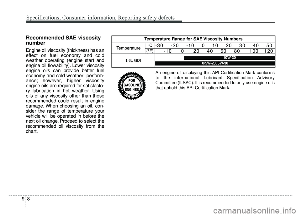
Recommended SAE viscosity
number
Engine oil viscosity (thickness) has an
effect on fuel economy and cold
weather operating (engine start and
engine oil flowability). Lower viscosity
engine oils can provide better fuel
economy and cold weather perform-
ance; however, higher viscosity
engine oils are required for satisfacto-
ry lubrication in hot weather. Using
oils of any viscosity other than those
recommended could result in engine
damage. When choosing an oil, con-
sider the range of temperature your
vehicle will be operated in before the
next oil change. Proceed to select the
recommended oil viscosity from the
chart.
Temperature Range for SAE Viscosity Numbers
Temperature°C
(°F)-30 -20 -10 0 10 20 30 40 50 -10 0 20 40 60 80 100 120
1.6L GDI10W-30
0/5W-20, 5W-30
An engine oil displaying this API Certification Mark conforms
to the international Lubricant Specification Advisory
Committee (ILSAC). It is recommended to only use engine oils
that uphold this API Certification Mark.