Page 150 of 626

After a trip:
•Check if any aftermarket equipment was installed (ad-
ditional lights, upfitter electrical accessories, audio sys-
tems, alarms) and review specifications if any (load and
Ignition Off Draw currents).
• Evaluate the latest driving cycles (distance, driving time
and parking time).
• The vehicle should have service performed if the mes-
sage is still present during consecutive trips and the
evaluation of the vehicle and driving pattern did not
help to identify the cause.
TRIP COMPUTER
Push and release the up or down arrow button until the
Trip A or Trip B icon is highlighted in the instrument
cluster display (Toggle left or right to select Trip A or Trip
B). Push and release the OK button to display the Trip
information. Trip A
•
Shows the total distance traveled for Trip A since the last
reset.
• Shows the elapsed time traveled for Trip A since the last
reset.
Trip B
• Shows the total distance traveled for Trip B since the last
reset.
• Shows the elapsed time traveled for Trip B since the last
reset.
Elapsed Time
Shows the total elapsed time of travel since the last reset
when the ignition switch is in the ACC position. Elapsed
time will increment when the ignition switch is in the ON
or START position.
To Reset A Trip Function
Reset will only occur while a resettable function is selected
(highlighted). Push and hold the OKbutton to clear the
resettable function being displayed.
148 GETTING TO KNOW YOUR INSTRUMENT PANEL
Page 213 of 626

WARNING!
•All occupants, including the driver, should not oper-
ate a vehicle or sit in a vehicle’s seat until the head
restraints are placed in their proper positions in
order to minimize the risk of neck injury in the event
of a collision.
• Do not place items over the top of the Active Head
Restraint, such as coats, seat covers or portable DVD
players. These items may interfere with the opera-
tion of the Active Head Restraint in the event of a
collision and could result in serious injury or death.
• Active Head Restraints may be deployed if they are
struck by an object such as a hand, foot or loose
cargo. To avoid accidental deployment of the Active
Head Restraint, ensure that all cargo is secured, as
loose cargo could contact the Active Head Restraint
during sudden stops. Failure to follow this warning
could cause personal injury if the Active Head Re-
straint is deployed.
NOTE: For more information on properly adjusting and
positioning the head restraint, refer to “Head Restraints” in
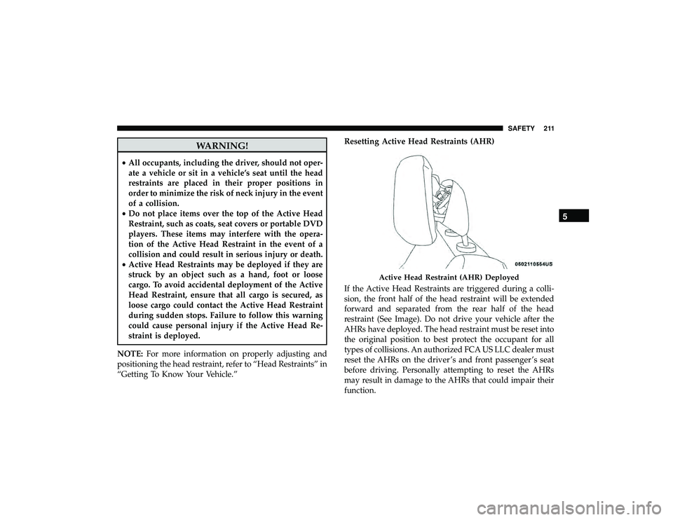
“Getting To Know Your Vehicle.” Resetting Active Head Restraints (AHR)
If the Active Head Restraints are triggered during a colli-
sion, the front half of the head restraint will be extended
forward and separated from the rear half of the head
restraint (See Image). Do not drive your vehicle after the
AHRs have deployed. The head restraint must be reset into
the original position to best protect the occupant for all
types of collisions. An authorized FCA US LLC dealer must
reset the AHRs on the driver ’s and front passenger ’s seat
before driving. Personally attempting to reset the AHRs
may result in damage to the AHRs that could impair their
function.
Page 214 of 626
WARNING!
Deployed AHRs are not able to best protect you in all
types of collisions. Have deployed AHRs reset by an
authorized dealer immediately.
Supplemental Restraint Systems (SRS)
Some of the safety features described in this section may be
standard equipment on some models, or may be optional
equipment on others. If you are not sure, ask an authorized
dealer.
The air bag system must be ready to protect you in a
collision. The Occupant Restraint Controller (ORC) moni-
tors the internal circuits and interconnecting wiring asso-
ciated with the electrical Air Bag System Components.
Your vehicle may be equipped with the following Air Bag
System Components:
Air Bag System Components
•Occupant Restraint Controller (ORC)
• Air Bag Warning Light
Page 225 of 626

Your vehicle may also be designed to perform any of these
other functions in response to the Enhanced Accident
Response System:
•Turn off the Fuel Filter Heater, Turn off the HVAC
Blower Motor, Close the HVAC Circulation Door
• Cut off battery power to the:
• Engine
• Electric Motor (if equipped)
• Electric power steering
• Brake booster
• Electric park brake
• Automatic transmission gear selector
• Horn
• Front wiper
• Headlamp washer pump NOTE:
After an accident, remember to cycle the ignition
to the STOP (OFF/LOCK) position and remove the key
from the ignition switch to avoid draining the battery.
Carefully check the vehicle for fuel leaks in the engine
compartment and on the ground near the engine compart-
ment and fuel tank before resetting the system and starting
the engine. If there are no fuel leaks or damage to the
vehicle electrical devices (e.g. headlights) after an accident,
reset the system by following the procedure described
below. If you have any doubt, contact an authorized dealer.
Enhanced Accident Response System Reset
Procedure
In order to reset the Enhanced Accident Response System
functions after an event, the ignition switch must be
changed from ignition START or ON/RUN to ignition OFF.
Carefully check the vehicle for fuel leaks in the engine
compartment and on the ground near the engine compart-
ment and fuel tank before resetting the system and starting
the engine.
5
SAFETY 223
Page 272 of 626

Transmission Limp Home Mode
Transmission function is monitored electronically for ab-
normal conditions. If a condition is detected that could
result in transmission damage, Transmission Limp Home
Mode is activated. In this mode, the transmission may
operate only in certain gears, or may not shift at all. Vehicle
performance may be severely degraded and the engine
may stall. In some situations, the transmission may not
re-engage if the engine is turned off and restarted. The
Malfunction Indicator Light (MIL) may be illuminated. A
message in the instrument cluster will inform the driver of
the more serious conditions, and indicate what actions may
be necessary.
In the event of a momentary problem, the transmission can
be reset to regain all forward gears by performing the
following steps:
NOTE:In cases where the instrument cluster message
indicates the transmission may not re-engage after engine
shutdown, perform this procedure only in a desired loca-
tion (preferably, at an authorized dealer).
1. Stop the vehicle.
2. Shift the transmission into PARK, if possible. If not, shift the transmission to NEUTRAL. 3. Push and hold the ignition switch until the engine turns
OFF.
4. Wait approximately 30 seconds.
5. Restart the engine.
6. Shift into the desired gear range. If the problem is no longer detected, the transmission will return to normal
operation.
NOTE: Even if the transmission can be reset, we recom-
mend that you visit an authorized dealer at your earliest
possible convenience. An authorized dealer has diagnostic
equipment to assess the condition of your transmission.
If the transmission cannot be reset, authorized dealer
service is required.
AutoStick
AutoStick is a driver-interactive transmission feature pro-
viding manual shift control, giving you more control of the
vehicle. AutoStick allows you to maximize engine braking,
eliminate undesirable upshifts and downshifts, and im-
prove overall vehicle performance. This system can also
provide you with more control during passing, city driv-
ing, cold slippery conditions, mountain driving, trailer
towing, and many other situations.
270 STARTING AND OPERATING
Page 292 of 626

2. The “STOP/START OFF” message will appear in instru-ment cluster display within the Stop/Start section. Refer
to “Instrument Cluster” in “Getting To Know Your
Instrument Panel” for further information.
3. At the next vehicle stop (after turning off the STOP/ START system), the engine will not be stopped.
4. The STOP/START system will reset itself back to an ON condition every time the ignition is turned off and back
on.
To Manually Turn On The Stop/Start System
Push the STOP/START OFF switch (located on the switch
bank). The light on the switch will turn off.
System Malfunction
If there is a malfunction in the STOP/START system, the
system will not shut down the engine. A “SERVICE STOP/
START SYSTEM” message will appear in the instrument
cluster display. Refer to “Instrument Cluster Display“ in
“Getting to Know Your Instrument Panel” for further
information.
If the “SERVICE STOP/START SYSTEM” message appears
in the instrument cluster display, have the system checked
by an authorized dealer.
SPEED CONTROL — IF EQUIPPED
When engaged, the Speed Control takes over accelerator
operations at speeds greater than 20 mph (32 km/h).
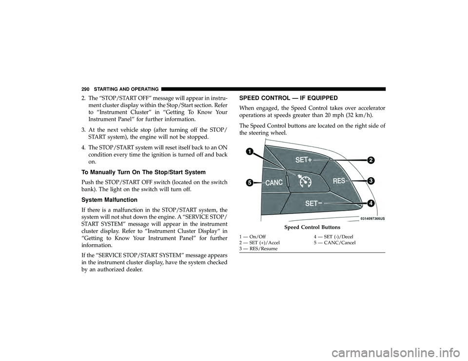
The Speed Control buttons are located on the right side of
the steering wheel.
Page 293 of 626
NOTE:In order to ensure proper operation, the Speed
Control System has been designed to shut down if multiple
Speed Control functions are operated at the same time. If
this occurs, the Speed Control System can be reactivated by
pushing the Speed Control on/off button and resetting the
desired vehicle set speed.
Page 296 of 626
NOTE:
•If the sensor does not detect a vehicle ahead of you, ACC
will maintain a fixed set speed.
• If the ACC sensor detects a vehicle ahead, ACC will
apply limited braking or accelerate (not to exceed the
original set speed) automatically to maintain a preset
following distance, while matching the speed of the
vehicle ahead.
The Cruise Control system has two control modes:
• Adaptive Cruise Control mode for maintaining an ap-
propriate distance between vehicles.
• Normal (Fixed Speed) Cruise Control mode for cruising
at a constant preset speed. For additional information,
refer to “Normal (Fixed Speed) Cruise Control Mode” in
this section.
NOTE: Normal (Fixed Speed) Cruise Control will not react
to preceding vehicles. Always be aware of the mode
selected.
You can change the mode by using the Cruise Control
buttons. The two control modes function differently. Al-
ways confirm which mode is selected.