Page 2 of 564
CALIFORNIA PROPOSITION 65 WARNING
WARNING
Operating, servicing and maintaining a passenger vehicle or
off-highway motor vehicle can expose you to chemicals
including engine exhaust, carbon monoxide, phthalates, and
lead, which are known to the State of California to cause
cancer and birth defects or other reproductive harm. To
minimize exposure, avoid breathing exhaust, do not idle the
engine except as necessary, service your vehicle in a well-
ventilated area and wear gloves or wash your hands
frequently when servicing your vehicle. For more information
go to www.P65Warnings.ca.gov/passenger-vehicle.
Page 9 of 564
0 Illustrated table of contents
Air bags, seat belts and child restraints........... 0-2
Exterior front ................................... 0-3
Exterior rear .................................... 0-4
Passenger compartment ......................... 0-5 Instrument panel
................................ 0-6
Engine compartment check locations ............. 0-8
Warning and indicator lights ..................... 0-9
Page 11 of 564
1. Engine hood (P. 3-24)
2. Wiper and washer switch (P. 2-35)Wiper blades (P. 8-16)
3. Windshield (P. 8-16)
4. Power windows (P. 2-66)
5. Door locks (P. 3-4) INFINITI Intelligent Key (P. 3-7)
Keys (P. 3-2)
6. Mirrors (P. 3-36) Side camera (if so equipped)
(P. 4-11)
7. Tire pressure (P. 8-26) Flat tire (P. 6-3)
Tire chains (P. 8-26)
8. Replacing bulbs (P. 8-23) Headlight switch (P. 2-39)
Turn signal switch (P. 2-39)
LED Daytime Running Lights (DRL)
system (P. 2-39)
9. Fog light switch (if so equipped)
(P. 2-39)
10. Sonar sensors (if so equipped)
(P. 5-186)
11. Front camera (if so equipped)
(P. 4-11)
See the page number indicated in parenthe-
ses for operating details.
LIC3787
EXTERIOR FRONT
Illustrated table of contents0-3
Page 16 of 564
KR20DDET engine
1. Engine coolant reservoir (P. 8-4)
2. Drive belt location (P. 8-13)
3. Air filter (P. 8-15)
4. Brake fluid reservoir (P. 8-10)
5. Battery (P. 8-11)
6. Fuse/Fusible link box (P. 8-19)
7. Windshield-washer fluid reservoir(P. 8-10)
8. Engine oil filler cap (P. 8-6)
9. Engine oil dipstick (P. 8-6)
Refer to the page number indicated in paren-
theses for operating details.
LDI3173
ENGINE COMPARTMENT CHECK
LOCATIONS
0-8Illustrated table of contents
Page 21 of 564

FRONT POWER SEAT
ADJUSTMENT
Operating tips
∙ The power seat motor has an auto-resetoverload protection circuit. If the motor
stops during operation, wait 30 seconds
then reactivate the switch.
∙ Do not operate the power seat switch for a long period of time when the engine is
off. This will discharge the battery. For additional information, refer to “Auto-
matic drive positioner” in the “Pre-driving
checks and adjustments” section of this
manual.Forward and backward
Moving the switch as shown will slide the
seat forward or backward to the desired po-
sition.
Reclining
Move the recline switch as shown until the
desired angle is obtained. The reclining feature allows adjustment of
the seatback for occupants of different sizes
for added comfort and to help obtain proper
seat belt fit. For additional information, refer
to “Precautions on seat belt usage” in this
section. Also, the seatback can be reclined to
allow occupants to rest when the vehicle is
stopped and the shift lever is in P (Park).
LRS2985
Safety—Seats, seat belts and supplemental restraint system1-3
Page 84 of 564

2 Instruments and controls
Instrument panel.................................2-2
Meters and gauges ...............................2-4
Speedometer and odometer ...................2-4
Tachometer ...................................2-6
Engine coolant temperature gauge .............2-6
Fuel gauge ....................................2-7
Variable Compression Turbo ...................2-7
Warning lights, indicator lights and audible
reminders ........................................2-9
Checking lights .............................. 2-10
Warning lights .............................. 2-10
Indicator lights ............................... 2-15
Audible reminders ........................... 2-18
Vehicle information display .....................2-19
How to use the vehicle information
display ...................................... 2-20
Startup display .............................. 2-20
Resetting the trip computer ..................2-20
Oil control system ........................... 2-20
Vehicle information display warnings and
indicators ................................... 2-24Security systems
............................... 2-32
Vehicle security system ......................2-32
INFINITI Vehicle Immobilizer System .........2-33
Wiper and washer switch .......................2-35
Switch operation ............................ 2-35
Rain-sensing auto wiper system
(if so equipped) .............................. 2-36
Rear switch operation ....................... 2-37
Rear window defroster, outside mirror
defroster, and wiper deicer (if so equipped)
switch ......................................... 2-39
Headlight switch ............................... 2-39
Headlight control switch .....................2-39
LED Daytime Running Lights (DRL)
system ...................................... 2-44
Instrument brightness control ................2-45
Turn signal switch ........................... 2-45
Fog light switch (if so equipped) .............2-46
Horn ........................................... 2-46
Climate controlled seat switches
(if so equipped) ................................. 2-47
Page 88 of 564
1. Tachometer
2. Warning and indicator lights
3. Vehicle information displayOdometer
Twin trip odometer
Transmission position indicator 4. Speedometer
5. Fuel gauge
6. Engine coolant temperature gauge
SPEEDOMETER AND
ODOMETER
This vehicle is equipped with a speedometer
and odometer. The speedometer is located
on the right side of the meter cluster. The
odometer is located within the vehicle infor-
mation display.
LIC3846
METERS AND GAUGES
2-4Instruments and controls
Page 90 of 564

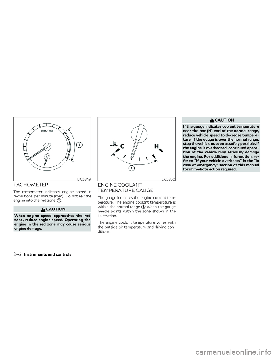
TACHOMETER
The tachometer indicates engine speed in
revolutions per minute (rpm). Do not rev the
engine into the red zone
�1.
CAUTION
When engine speed approaches the red
zone, reduce engine speed. Operating the
engine in the red zone may cause serious
engine damage.
ENGINE COOLANT
TEMPERATURE GAUGE
The gauge indicates the engine coolant tem-
perature. The engine coolant temperature is
within the normal range
�1when the gauge
needle points within the zone shown in the
illustration.
The engine coolant temperature varies with
the outside air temperature and driving con-
ditions.
CAUTION
If the gauge indicates coolant temperature
near the hot (H) end of the normal range,
reduce vehicle speed to decrease tempera-
ture. If the gauge is over the normal range,
stop the vehicle as soon as safely possible. If
the engine is overheated, continued opera-
tion of the vehicle may seriously damage
the engine. For additional information, re-
fer to “If your vehicle overheats” in the “In
case of emergency” section of this manual
for immediate action required.
LIC3849LIC3850
2-6Instruments and controls