Page 193 of 436
�ARearView Monitor display
�BINFINITI controller
�C
Page 194 of 436
CAUTION
Do not scratch the camera lens when clean-
ing dirt or snow from the lens.
The RearView Monitor system automatically
shows a rear view of the vehicle when the
shift lever is placed in the R (Reverse) posi-
tion. When activating the RearView Monitor,
the guide lines, the icons and the messages
may not be displayed immediately.
The radio can still be heard while the Rear-
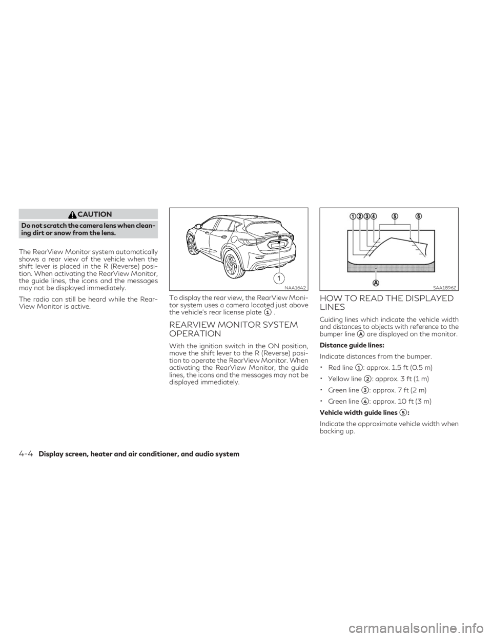
View Monitor is active.To display the rear view, the RearView Moni-
tor system uses a camera located just above
the vehicle’s rear license plate
�1.
REARVIEW MONITOR SYSTEM
OPERATION
With the ignition switch in the ON position,
move the shift lever to the R (Reverse) posi-
tion to operate the RearView Monitor. When
activating the RearView Monitor, the guide
lines, the icons and the messages may not be
displayed immediately.
HOW TO READ THE DISPLAYED
LINES
Guiding lines which indicate the vehicle width
and distances to objects with reference to the
bumper line
�Aare displayed on the monitor.
Distance guide lines:
Indicate distances from the bumper.
•Red line�1: approx. 1.5 ft (0.5 m)
•Yellow line�2: approx. 3 ft (1 m)
•Green line�3: approx. 7 ft (2 m)
•Green line�4: approx. 10 ft (3 m)
Vehicle width guide lines
�5:
Indicate the approximate vehicle width when
backing up.
NAA1642SAA1896Z
4-4Display screen, heater and air conditioner, and audio system
Page 195 of 436
Predicted course lines�6:
Indicate the predicted course when backing up.
The predicted course lines will be displayed on
the monitor when the shift lever is in the R
(Reverse) position and the steering wheel is
turned. The predicted course lines will move
depending on how much the steering wheel is
turned and will not be displayed while the
steering wheel is in the neutral position.
The vehicle width guide lines and the width
of the predicted course lines are wider than
the actual width and course.
DIFFERENCE BETWEEN
PREDICTED AND ACTUAL
DISTANCES
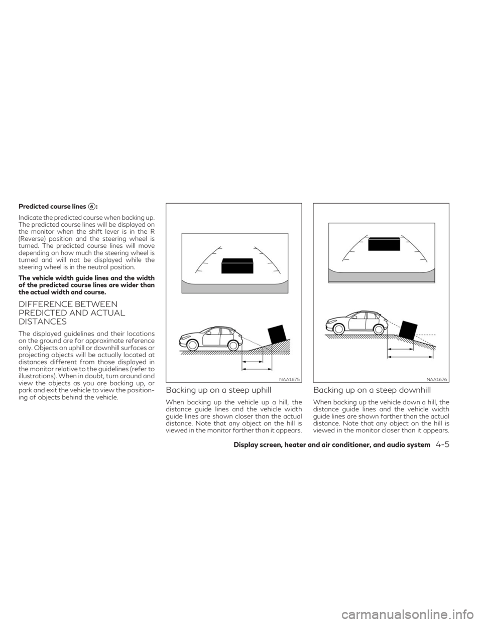
The displayed guidelines and their locations
on the ground are for approximate reference
only. Objects on uphill or downhill surfaces or
projecting objects will be actually located at
distances different from those displayed in
the monitor relative to the guidelines (refer to
illustrations). When in doubt, turn around and
view the objects as you are backing up, or
park and exit the vehicle to view the position-
ing of objects behind the vehicle.
Backing up on a steep uphill
When backing up the vehicle up a hill, the
distance guide lines and the vehicle width
guide lines are shown closer than the actual
distance. Note that any object on the hill is
viewed in the monitor farther than it appears.
Backing up on a steep downhill
When backing up the vehicle down a hill, the
distance guide lines and the vehicle width
guide lines are shown farther than the actual
distance. Note that any object on the hill is
viewed in the monitor closer than it appears.
NAA1675NAA1676
Display screen, heater and air conditioner, and audio system4-5
Page 197 of 436
•When the steering wheel is turned with
the ignition switch in the ACC position,
the predicted course lines may be dis-
played incorrectly.
The vehicle width and predicted course lines
are wider than the actual width and course.1. Visually check that the parking space is
safe before parking your vehicle.
2. The rear view of the vehicle is displayed on
the screen
�Aas illustrated when the shift
lever is moved to the R (Reverse) position.
When activating the RearView Monitor,
the guide lines, the icons and the mes-
sages may not be displayed immediately.
SAA1897
Display screen, heater and air conditioner, and audio system4-7
Page 198 of 436
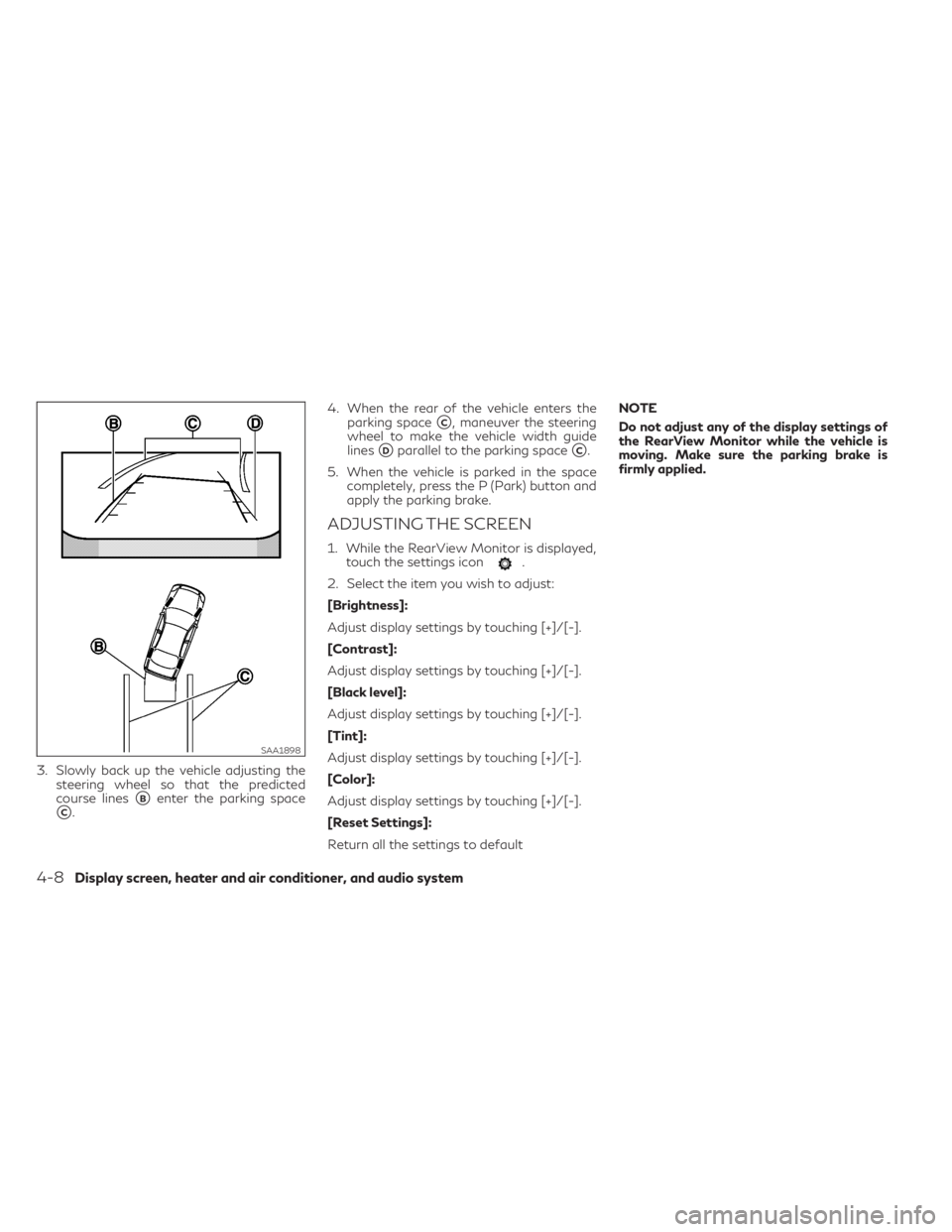
3. Slowly back up the vehicle adjusting the
steering wheel so that the predicted
course lines
�Benter the parking space
�C.4. When the rear of the vehicle enters the
parking space
�C, maneuver the steering
wheel to make the vehicle width guide
lines
�Dparallel to the parking space�C.
5. When the vehicle is parked in the space
completely, press the P (Park) button and
apply the parking brake.
ADJUSTING THE SCREEN
1. While the RearView Monitor is displayed,
touch the settings icon.
2. Select the item you wish to adjust:
[Brightness]:
Adjust display settings by touching [+]/[-].
[Contrast]:
Adjust display settings by touching [+]/[-].
[Black level]:
Adjust display settings by touching [+]/[-].
[Tint]:
Adjust display settings by touching [+]/[-].
[Color]:
Adjust display settings by touching [+]/[-].
[Reset Settings]:
Return all the settings to defaultNOTE
Do not adjust any of the display settings of
the RearView Monitor while the vehicle is
moving. Make sure the parking brake is
firmly applied.
SAA1898
4-8Display screen, heater and air conditioner, and audio system
Page 203 of 436
The screen displayed on the Around View®
Monitor will automatically return to the pre-
vious screen 3 minutes after the
button has been pushed while the shift lever
is in a position other than the R (Reverse)
position.
Available views
WARNING
•The distance guide lines and the vehicle
width lines should be used as a reference
only when the vehicle is on a paved, level
surface. The distance viewed on the
monitor is for reference only and may be
different than the actual distance be-
tween the vehicle and displayed objects.
•Use the displayed lines and the bird's-
eye view as a reference. The lines and the
bird's-eye view are greatly affected by
the number of occupants, fuel level, ve-
hicle position, road condition and road
grade.
•When driving the vehicle up a hill, ob-
jects viewed in the monitor are farther
than they appear. When driving the ve-
hicle down a hill, objects viewed in the
monitor are closer than they appear.
•Objects in the monitor will appear visu-
ally opposite compared to when viewed
in the rear view and outside mirrors.
•Use the mirrors or actually look to prop-
erly judge distances to other objects.
•The distance between objects viewed in
the rear view differs from actual dis-
tance because a wide-angle lens is used.
•The displayed lines on the rear view will
appear slightly off to the right because
the rear view camera is not installed in
the rear center of the vehicle.
Front view
Rear view
SAA1840Z
SAA1896Z
Display screen, heater and air conditioner, and audio system4-13
Page 204 of 436
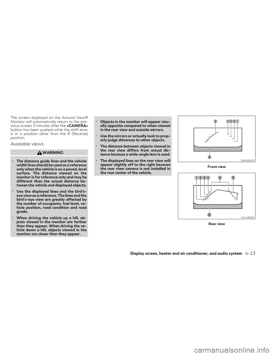
Front and rear views:
Guiding lines, which indicate the vehicle width
and distances to objects with reference to the
vehicle body line
�A, are displayed on the
monitor.
Distance guide lines:
Indicate distances from the vehicle body:
•Red line�1: approx.1.5 ft (0.5 m)
•Yellow line�2: approx. 3 ft (1 m)
•Green line�3: approx. 7 ft (2 m)
•Green line�4: approx. 10 ft (3 m)
Vehicle width guide lines
�5:
Indicate the approximate vehicle width when
backing up.Predicted course lines
�6:
Indicate the predicted course when operating
the vehicle. The predicted course lines will be
displayed on the monitor when the steering
wheel is turned. The predicted course lines
will move depending on how much the steer-
ing wheel is turned and will not be displayed
while the steering wheel is in the straight
ahead position.
The front view will not be displayed when the
vehicle speed is above 10 km/h (6 MPH).
NOTE
When the monitor displays the front view
and the steering wheel turns about 90 de-
grees or less from the neutral position, both
the right and left predicted course lines
�6are displayed. When the steering wheel
turns about 90 degrees or more, a line is dis-
played only on the opposite side of the turn.Bird's-eye view:
WARNING
•Objects in the bird's-eye view will ap-
pear farther than the actual distance.
•Tall objects, such as a curb or a vehicle,
may be misaligned or not displayed at
the seam of the views.
•Objects that are above the camera can-
not be displayed.
•The view for the bird's-eye view may be
misaligned when the camera position
alters.
•A line on the ground may be misaligned
and is not seen as being straight at the
seam of the views. The misalignment will
increase as the line proceeds away from
the vehicle.
•Tire angle display does not indicate the
actual tire angle.
4-14Display screen, heater and air conditioner, and audio system
Page 205 of 436
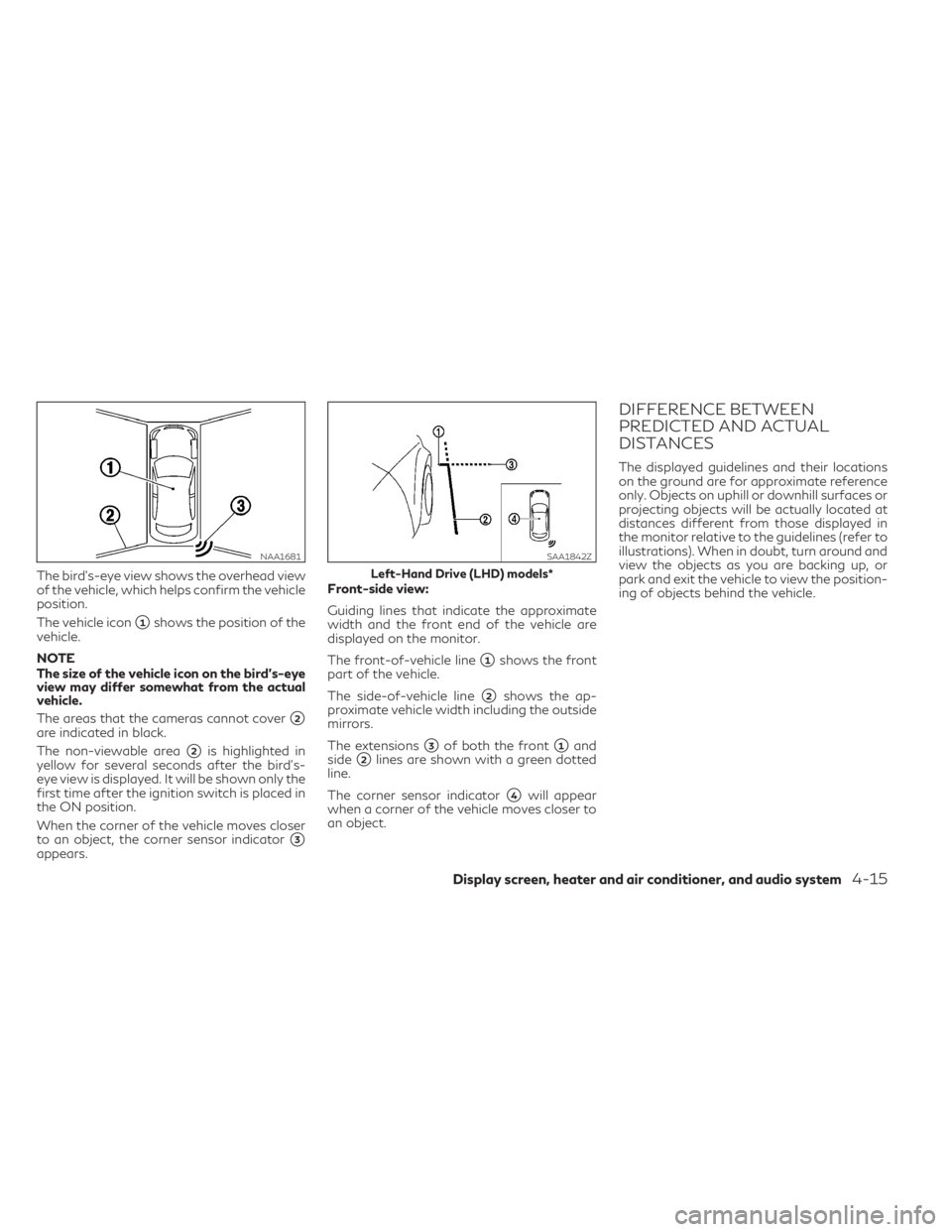
The bird's-eye view shows the overhead view
of the vehicle, which helps confirm the vehicle
position.
The vehicle icon
�1shows the position of the
vehicle.
NOTE
The size of the vehicle icon on the bird's-eye
view may differ somewhat from the actual
vehicle.
The areas that the cameras cannot cover
�2are indicated in black.
The non-viewable area
�2is highlighted in
yellow for several seconds after the bird's-
eye view is displayed. It will be shown only the
first time after the ignition switch is placed in
the ON position.
When the corner of the vehicle moves closer
to an object, the corner sensor indicator
�3appears.Front-side view:
Guiding lines that indicate the approximate
width and the front end of the vehicle are
displayed on the monitor.
The front-of-vehicle line
�1shows the front
part of the vehicle.
The side-of-vehicle line
�2shows the ap-
proximate vehicle width including the outside
mirrors.
The extensions
�3of both the front�1and
side
�2lines are shown with a green dotted
line.
The corner sensor indicator
�4will appear
when a corner of the vehicle moves closer to
an object.
DIFFERENCE BETWEEN
PREDICTED AND ACTUAL
DISTANCES
The displayed guidelines and their locations
on the ground are for approximate reference
only. Objects on uphill or downhill surfaces or
projecting objects will be actually located at
distances different from those displayed in
the monitor relative to the guidelines (refer to
illustrations). When in doubt, turn around and
view the objects as you are backing up, or
park and exit the vehicle to view the position-
ing of objects behind the vehicle.
NAA1681SAA1842Z
Left-Hand Drive (LHD) models*
Display screen, heater and air conditioner, and audio system4-15