Page 403 of 491
7-29
7
Maintenance
A
AI
IR
R
C
C L
LE
E A
A N
N E
ER
R
Filter Replacement
The air cleaner filter can be cleaned
for inspection using compressed air.
Do not attempt to wash or to rinse it,
as water will damage the filter.
If soiled, the air cleaner filter must be
replaced. 1. Loosen the air cleaner cover
attaching clips and open the cover.
2. Wipe the inside of the air cleaner.
3. Replace the air cleaner filter. 4. Insert the air cleaner cover in the
hinge and engage the clamp after
closing the cover.
5. Check that the cover is firmly installed.
OJS078016
OJS078017
OJS078015
OJS078047
Page 410 of 491
7-36
Maintenance
By jump starting
After a jump start from a good bat-
tery, drive the vehicle for 20-30 min-
utes before it is shutoff. The vehicle
may not restart if you shut it off
before the battery had a chance to
adequately recharge. See "Jump
Starting" in chapter 6 for more details
on jump starting procedures.
Information
An inappropriately disposedbattery can be harmful to
the environment and human
health. Dispose of the bat-
tery according to your local
law(s) or regulations.
Reset Features
The following items may need to be
reset after the battery has been dis-
charged or the battery has been dis-
connected. See chapter 3 or 4 for:
Power Windows
Trip Computer
Climate Control System
Clock
Audio System
Sunroof
i
Watch the battery during
charging, and stop or reduce
the charging rate if the battery
cells begin boiling violently.
The negative battery cable
must be removed first and
installed last when the battery
is disconnected. Disconnect
the battery charger in the fol-
lowing order:
(1) Turn off the battery charg- er main switch.
(2) Unhook the negative
clamp from the negative
battery terminal.
(3) Unhook the positive clamp from the positive battery
terminal.
Always use a genuine
HYUNDAI approved battery
when you replace the battery.
Page 421 of 491
7-47
7
Maintenance
Bead
The tire bead contains steel wires
wrapped by steel cords that hold the
tire onto the rim.
Bias Ply Tire
A pneumatic tire in which the plies
are laid at alternate angles less than
90 degrees to the centerline of the
tread.
Cold Tire Pressure
The amount of air pressure in a tire,
measured in pounds per square inch
(psi) or kilopascals (kPa) before a tire
has built up heat from driving.
Curb Weight
This means the weight of a motor
vehicle with standard and optional
equipment including the maximum
capacity of fuel, oil and coolant, but
without passengers and cargo.
DOT Markings
A code molded into the sidewall of a
tire signifying that the tire is in com-
pliance with the U.S. Department of
Transportation motor vehicle safety
standards. The DOT code includes
the Tire Identification Number (TIN),
an alphanumeric designator which
can also identify the tire manufactur-
er, production plant, brand and date
of production.
GVWR
Gross Vehicle Weight Rating
GAWR FRT
Gross Axle Weight Rating for the
Front Axle.
GAWR RR
Gross Axle Weight Rating for the
Rear axle.
Intended Outboard Sidewall
The side of an asymmetrical tire, that
must always face outward when
mounted on a vehicle.
Kilopascal (kPa)
The metric unit for air pressure.
Light truck(LT) tire
A tire designated by its manufacturer
as primarily intended for use on light-
weight trucks or multipurpose pas-
senger vehicles.
Load ratings
The maximum load that a tire is rated
to carry for a given inflation pressure.
Load Index
An assigned number ranging from 1
to 279 that corresponds to the load
carrying capacity of a tire.
Maximum Inflation Pressure
The maximum air pressure to which
a cold tire may be inflated. The max-
imum air pressure is molded onto the
sidewall.
Page 426 of 491
7-52
Maintenance
F
FU
U S
SE
E S
S
A vehicle's electrical system is pro-
tected from electrical overload dam-
age by fuses.
This vehicle has 2 (or 3) fuse panels,
one located in the driver's side panel
bolster, the other in the engine com-
partment near the battery. If any of your vehicle's lights, acces-
sories, or controls do not work, check
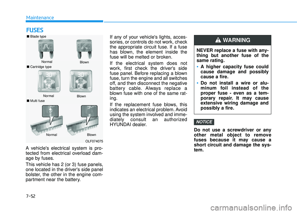
the appropriate circuit fuse. If a fuse
has blown, the element inside the
fuse will be melted or broken.
If the electrical system does not
work, first check the driver's side
fuse panel. Before replacing a blown
fuse, turn the engine and all switches
off, and then disconnect the negative
battery cable. Always replace a
blown fuse with one of the same rat-
ing.
If the replacement fuse blows, this
indicates an electrical problem. Avoid
using the system involved and imme-
diately consult an authorized
HYUNDAI dealer.
Do not use a screwdriver or any
other metal object to remove
fuses because it may cause a
short circuit and damage the sys-
tem.
NOTICE
NEVER replace a fuse with any-
thing but another fuse of the
same rating.
A higher capacity fuse could
cause damage and possibly
cause a fire.
Do not install a wire or alu-
minum foil instead of the
proper fuse - even as a tem-
porary repair. It may cause
extensive wiring damage and
possibly a fire.
WARNING ■Blade type
Normal
■ Cartridge type Blown
Normal
Blown
■ Multi fuse
Normal Blown
OLF074075
Page 438 of 491
7-64
Maintenance
Fuse NameFuse RatingProtected Component
SENSOR210A
G4FJ : Canister Close Valve, Oil Control Valve #1/#2, RCV Control Solenoid Valve, Purge Control Solenoid Valve, E/R Junction Block (C/FAN2 HI Relay)
G4NH : Canister Close Valve, Oil Control Valve #1/#2/#3, Electronic Thermostat, Variable Intake Solenoid Valve, Purge Control Solenoid Valve, E/R Junction Block (C/FAN 1 Low Relay, C/FAN 2 HI Relay)
ECU210AECM (G4FJ)
ECU120AECM/PCM
INJECTOR15AInjector #1/#2/#3/#4 (G4NH)
SENSOR115AOxygen Sensor (Up/Down)
IGN COIL20AIgnition Coil #1/#2/#3/#4
ECU315AECM/PCM
A/C10AA/CON COMP Relay (G4NH)
ECU510AECM/PCM
VACUUMPUMP215AVacuum Pump (G4FJ)
Engine compartment fuse panel
[G4FJ] : 1.6 T-GDI
[G4NH] : 2.0 MPI
Page 442 of 491
7-68
Maintenance
Headlamp, Position lamp,
Daytime Running Light, Turn
signal lamp and Side marker
Type A
(1) Headlamp (High)
(2) Headlamp (Low)
(3) Turn signal lamp
(4) Position lamp & Daytime running light (DRL)
(5) Side marker Always handle them carefully, and
avoid scratches and abrasions. If
the bulbs are lit, avoid contact with
liquids.
Never touch the glass with bare hands. Residual oil may cause the
bulb to overheat and burst when lit.
A bulb should be operated only when installed in a headlamp.
If a bulb becomes damaged or cracked, replace it immediately
and carefully dispose of it.
Handle halogen bulbs with
care. Halogen bulbs contain
pressurized gas that will pro-
duce flying pieces of glass that
could cause injuries if broken.
Wear eye protection when
changing a bulb. Allow the
bulb to cool down before han-
dling it.
WARNING
OLMB073042L
OJS078057N
Page 445 of 491
7-71
7
Maintenance
Always handle them carefully, andavoid scratches and abrasions. If
the bulbs are lit, avoid contact with
liquids.
Never touch the glass with bare hands. Residual oil may cause the
bulb to overheat and burst when lit.
A bulb should be operated only when installed in a headlamp.
If a bulb becomes damaged or cracked, replace it immediately
and carefully dispose of it.
Headlamp (Low beam), side mark-
er, position lamp and daytime run-
ning light
Your vehicle is equipped with LED
lamps. LED lamps do not have
replaceable bulbs. If the LED lamp
does not operate, have the vehicle
checked by an authorized HYUNDAI
dealer.
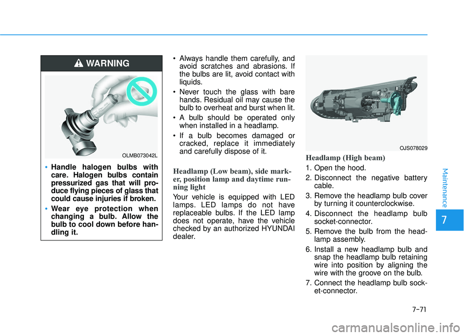
Headlamp (High beam)
1. Open the hood.
2. Disconnect the negative battery cable.
3. Remove the headlamp bulb cover by turning it counterclockwise.
4. Disconnect the headlamp bulb socket-connector.
5. Remove the bulb from the head- lamp assembly.
6. Install a new headlamp bulb and snap the headlamp bulb retaining
wire into position by aligning the
wire with the groove on the bulb.
7. Connect the headlamp bulb sock- et-connector.
OJS078029
Handle halogen bulbs with
care. Halogen bulbs contain
pressurized gas that will pro-
duce flying pieces of glass that
could cause injuries if broken.
Wear eye protection when
changing a bulb. Allow the
bulb to cool down before han-
dling it.
WARNING
OLMB073042L
Page 453 of 491
7-79
7
Maintenance
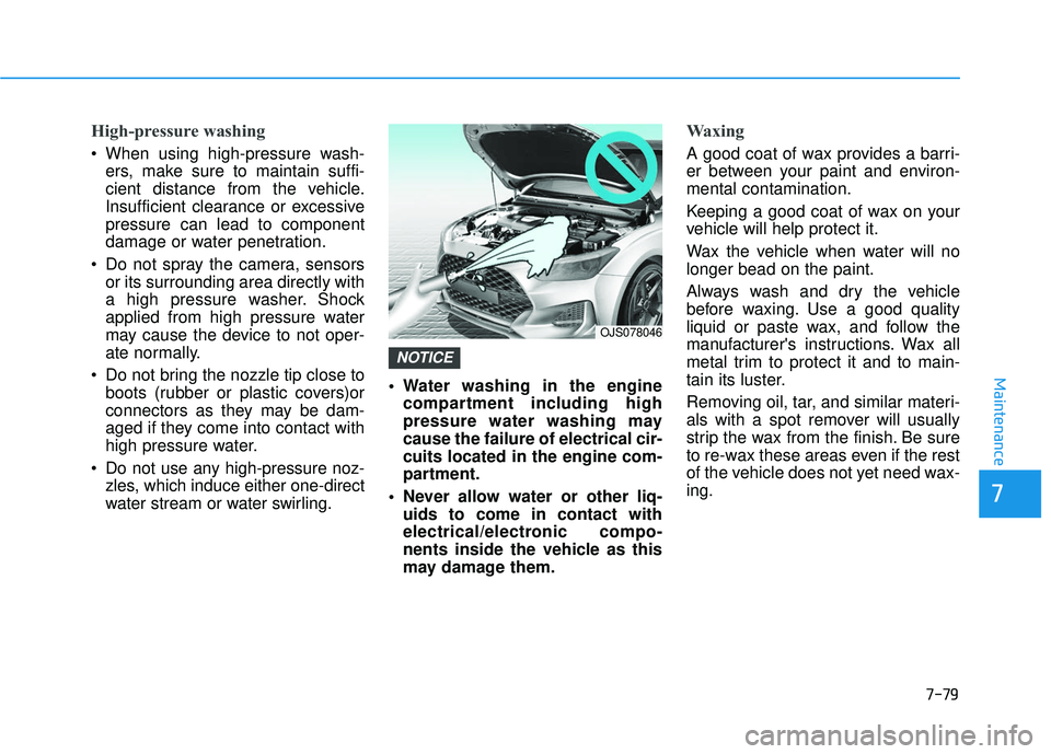
High-pressure washing
When using high-pressure wash-ers, make sure to maintain suffi-
cient distance from the vehicle.
Insufficient clearance or excessive
pressure can lead to component
damage or water penetration.
Do not spray the camera, sensors or its surrounding area directly with
a high pressure washer. Shock
applied from high pressure water
may cause the device to not oper-
ate normally.
Do not bring the nozzle tip close to boots (rubber or plastic covers)or
connectors as they may be dam-
aged if they come into contact with
high pressure water.
Do not use any high-pressure noz- zles, which induce either one-direct
water stream or water swirling. Water washing in the engine
compartment including high
pressure water washing may
cause the failure of electrical cir-
cuits located in the engine com-
partment.
Never allow water or other liq- uids to come in contact with
electrical/electronic compo-
nents inside the vehicle as this
may damage them.
Waxing
A good coat of wax provides a barri-
er between your paint and environ-
mental contamination.
Keeping a good coat of wax on your
vehicle will help protect it.
Wax the vehicle when water will no
longer bead on the paint.
Always wash and dry the vehicle
before waxing. Use a good quality
liquid or paste wax, and follow the
manufacturer's instructions. Wax all
metal trim to protect it and to main-
tain its luster.
Removing oil, tar, and similar materi-
als with a spot remover will usually
strip the wax from the finish. Be sure
to re-wax these areas even if the rest
of the vehicle does not yet need wax-
ing.
NOTICE
OJS078046