2019 Hyundai Tucson symbol
[x] Cancel search: symbolPage 6 of 546

F6
Introduction
We want to help you get the greatest
possible driving pleasure from your
vehicle. Your Owner’s Manual can
assist you in many ways. To gain an
overview of the contents of your
Owner’s Manual, use the Table of
Contents in the front of the manual.
The first page of each Chapter
includes a detailed Table of Contents
of the Topics in that Chapter.
To quickly locate information about
your vehicle, use the Index in the
back of the manual. It is an alphabet-
ical list of what is in this manual and
the page number where it can be
found.
For your convenience, we have
incorporated tabs on the right-hand
page edges. These tabs are coded
with the Chapter titles to assist you
with navigating through the manual.Your safety, and the safety of others,
is very important. This Owner’s
Manual provides you with many safe-
ty precautions and operating proce-
dures. This information alerts you to
potential hazards that may hurt you
or others, as well as damage to your
vehicle.
Safety messages found on vehicle
labels and in this manual describe
these hazards and what to do to
avoid or reduce the risks.
Warnings and instructions contained
in this manual are for your safety.
Failure to follow safety warnings and
instructions can lead to serious injury
or death.Throughout this manual DANGER,
WARNING, CAUTION, NOTICE and
the SAFETY ALERT SYMBOL will
be used.
This is the safety alert sym-
bol. It is used to alert you to
potential physical injury haz-
ards. Obey all safety mes-
sages that follow this symbol
to avoid possible injury or
death. The safety alert sym-
bol precedes the signal words
DANGER, WARNING and
CAUTION.
H HO
OW
W
T
TO
O
U
US
SE
E
T
TH
HI
IS
S
M
MA
AN
NU
UA
AL
L
DANGER indicates a hazardous
situation which, if not avoided,
will result in death or serious
injury.
DANGER
WARNING indicates a hazardous
situation which, if not avoided,
could result in death or serious
injury.
WARNING
S SA
AF
FE
ET
TY
Y
M
ME
ES
SS
SA
AG
GE
ES
S
Page 61 of 546
Safety system of your vehicle
2
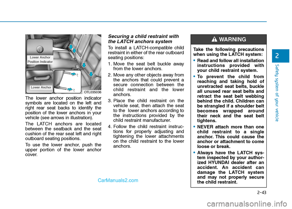
The lower anchor position indicator
symbols are located on the left and
right rear seat backs to identify the
position of the lower anchors in your
vehicle (see arrows in illustration).
The LATCH anchors are located
between the seatback and the seat
cushion of the rear seat left and right
outboard seating positions.
To use the lower anchor, push the
upper portion of the lower anchor
cover.
Securing a child restraint with
the LATCH anchors system
To install a LATCH-compatible child
restraint in either of the rear outboard
seating positions:
1. Move the seat belt buckle away
from the lower anchors.
2. Move any other objects away from
the anchors that could prevent a
secure connection between the
child restraint and the lower
anchors.
3. Place the child restraint on the
vehicle seat, then attach the seat
to the lower anchors according to
the instructions provided by the
child restraint manufacturer.
4. Follow the child restraint instruc-
tions for properly adjusting and
tightening the lower attachments
on the child restraint to the lower
anchors.
OTL035036
Lower Anchor
Position Indicator
Lower Anchor
Take the following precautions
when using the LATCH system:
Read and follow all installation
instructions provided with
your child restraint system.
To prevent the child from
reaching and taking hold of
unretracted seat belts, buckle
all unused rear seat belts and
retract the seat belt webbing
behind the child. Children can
be strangled if a shoulder belt
becomes wrapped around
their neck and the seat belt
tightens.
NEVER attach more than one
child restraint to a single
anchor. This could cause the
anchor or attachment to come
loose or break.
Always have the LATCH sys-
tem inspected by your author-
ized HYUNDAI dealer after an
accident. An accident can
damage the LATCH system
and may not properly secure
the child restraint.
WARNING
2-43
Page 72 of 546

2-54
Safety system of your vehicle
How Does the Air Bag System
Operate?
The SRS consists of the following
components:
1. Driver's front air bag module
2. Passenger's front air bag module
3. Side air bag modules
4. Curtain air bag modules
5. Retractor pre-tensioner assemblies
6. Air bag warning light
7. SRS control module (SRSCM)/
Rollover sensor
8. Front impact sensors
9. Side impact sensors10. Side pressure sensors
11. The front passenger's seat belt
buckle sensors
12. Emergency Fastening Device
(EFD)
13. Occupant classification system
The SRSCM (Supplemental Restraint
System Control Module) continually
monitors all SRS components while
the ignition switch is in the ON posi-
tion to determine if a crash impact is
severe enough to require air bag
deployment or pre-tensioner seat belt
deployment.
Information
The seat belt buckle sensor deter-
mines whether the front passenger's
seat belt is fastened. According to
whether the seat belt is fastened or not
and how severe the impact is, this sen-
sor provides the function to control
the SRS deployment.
SRS warning light
The SRS (Supplement Restraint
System) air bag warning light on the
instrument panel displays the air bag
symbol depicted in the illustration.
The system checks the air bag elec-
trical system for malfunctions. The
light indicates that there is a potential
malfunction with your air bag system,
which could include your side and
curtain air bags used for rollover pro-
tection.
i
ODH033104L/Q
Page 114 of 546
3-23
Convenient features of your vehicle
3
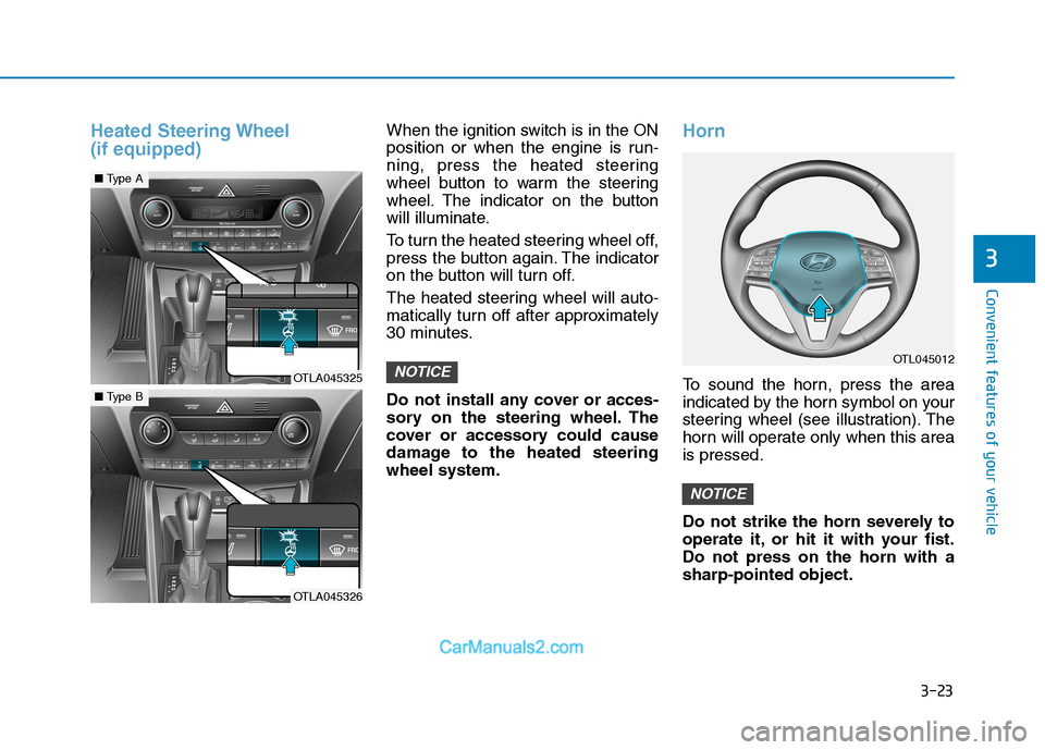
Heated Steering Wheel
(if equipped)When the ignition switch is in the ON
position or when the engine is run-
ning, press the heated steering
wheel button to warm the steering
wheel. The indicator on the button
will illuminate.
To turn the heated steering wheel off,
press the button again. The indicator
on the button will turn off.
The heated steering wheel will auto-
matically turn off after approximately
30 minutes.
Do not install any cover or acces-
sory on the steering wheel. The
cover or accessory could cause
damage to the heated steering
wheel system.Horn
To sound the horn, press the area
indicated by the horn symbol on your
steering wheel (see illustration). The
horn will operate only when this area
is pressed.
Do not strike the horn severely to
operate it, or hit it with your fist.
Do not press on the horn with a
sharp-pointed object.
NOTICE
NOTICEOTL045012
OTLA045325
■Type A
OTLA045326
■Type B
Page 183 of 546
3-92
Convenient features of your vehicle
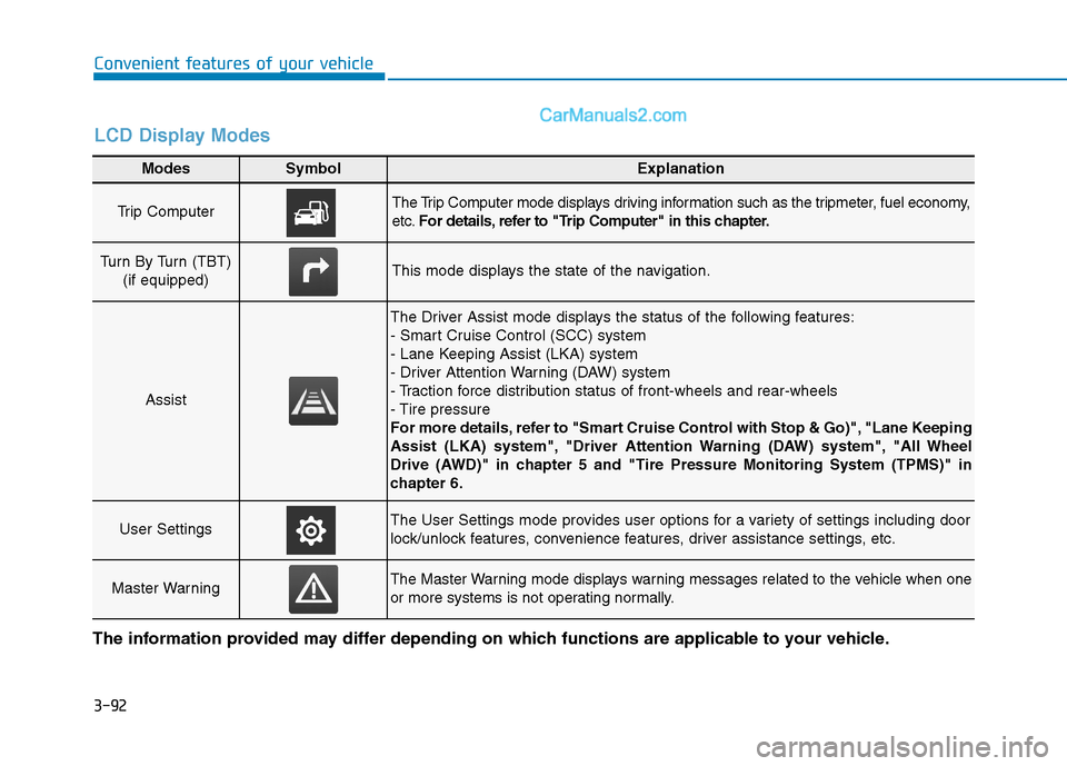
Modes SymbolExplanation
Trip Computer The Trip Computer mode displays driving information such as the tripmeter, fuel economy,
etc.For details, refer to "Trip Computer" in this chapter.
Turn By Turn (TBT)
(if equipped)This mode displays the state of the navigation.
Assist
The Driver Assist mode displays the status of the following features:
- Smart Cruise Control (SCC) system
- Lane Keeping Assist (LKA) system
- Driver Attention Warning (DAW) system
- Traction force distribution status of front-wheels and rear-wheels
- Tire pressure
For more details, refer to "Smart Cruise Control with Stop & Go)", "Lane Keeping
Assist (LKA) system", "Driver Attention Warning (DAW) system", "All Wheel
Drive (AWD)" in chapter 5 and "Tire Pressure Monitoring System (TPMS)" in
chapter 6.
User SettingsThe User Settings mode provides user options for a variety of settings including door
lock/unlock features, convenience features, driver assistance settings, etc.
Master WarningThe Master Warning mode displays warning messages related to the vehicle when one
or more systems is not operating normally.
The information provided may differ depending on which functions are applicable to your vehicle.
LCD Display Modes
Page 220 of 546
3-129
Convenient features of your vehicle
3
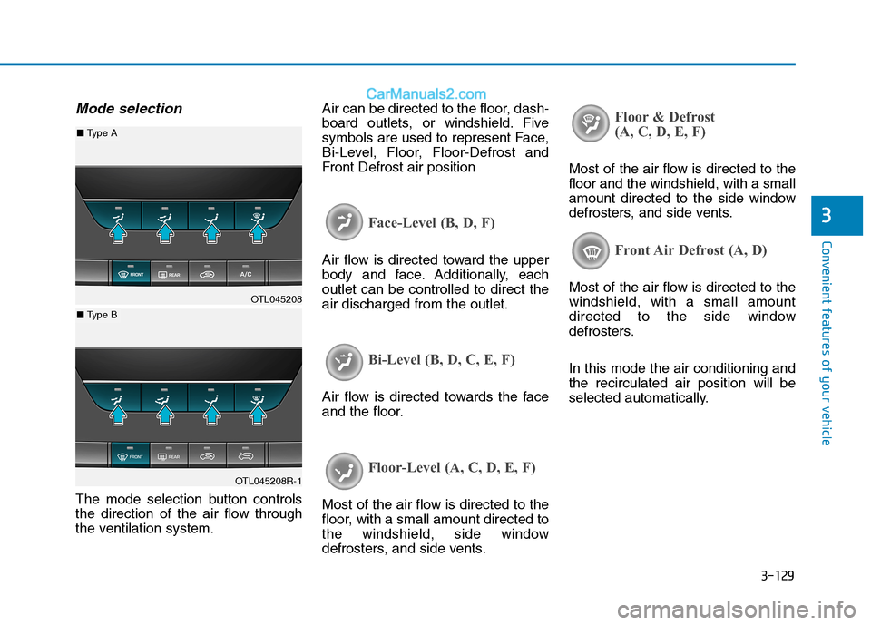
Mode selection
The mode selection button controls
the direction of the air flow through
the ventilation system.Air can be directed to the floor, dash-
board outlets, or windshield. Five
symbols are used to represent Face,
Bi-Level, Floor, Floor-Defrost and
Front Defrost air position
Face-Level (B, D, F)
Air flow is directed toward the upper
body and face. Additionally, each
outlet can be controlled to direct the
air discharged from the outlet.
Bi-Level (B, D, C, E, F)
Air flow is directed towards the face
and the floor.
Floor-Level (A, C, D, E, F)
Most of the air flow is directed to the
floor, with a small amount directed to
the windshield, side window
defrosters, and side vents.
Floor & Defrost
(A, C, D, E, F)
Most of the air flow is directed to the
floor and the windshield, with a small
amount directed to the side window
defrosters, and side vents.
Front Air Defrost (A, D)
Most of the air flow is directed to the
windshield, with a small amount
directed to the side window
defrosters.
In this mode the air conditioning and
the recirculated air position will be
selected automatically.OTL045208
OTL045208R-1
■ Type A
■ Type B
Page 227 of 546
3-136
Convenient features of your vehicle
Checking the amount of air
conditioner refrigerant and
compressor lubricant
When the amount of refrigerant is
low, the performance of the air con-
ditioning is reduced. Overfilling also
has a negative influence on the air
conditioning system.
Therefore, if abnormal operation is
found, have the system inspected by
an authorized HYUNDAI dealer.
It is important that the correct
type and amount of oil and refrig-
erant is used. Otherwise, damage
to the compressor and abnormal
system operation may occur.The air conditioning system should
be serviced by an authorized
HYUNDAI dealer.
Air Conditioning refrigerant label
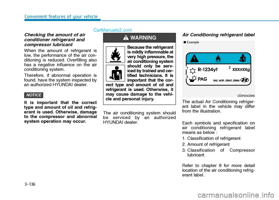
The actual Air Conditioning refriger-
ant label in the vehicle may differ
from the illustration.
Each symbols and specification on
air conditioning refrigerant label
means as below :
1. Classification of refrigerant
2. Amount of refrigerant
3. Classification of Compressor
lubricant
Refer to chapter 8 for more detail
location of the air conditioning refrig-
erant label.
NOTICE
Because the refrigerant
is mildly inflammable at
very high pressure, the
air conditioning system
should only be serv-
iced by trained and cer-
tified technicians. It is
important that the cor-
rect type and amount of oil and
refrigerant is used.Otherwise, it
may cause damage to the vehi-
cle and personal injury.
WARNING
ODH043366
■Example
Page 240 of 546
3-149
Convenient features of your vehicle
3
If the air flow rate suddenly decreas-
es, the system should be checked at
an authorized HYUNDAI dealer.
Checking the amount of air
conditioner refrigerant and
compressor lubricant
When the amount of refrigerant is
low, the performance of the air con-
ditioning is reduced. Overfilling also
has a negative influence on the air
conditioning system.
Therefore, if abnormal operation is
found, have the system inspected by
an authorized HYUNDAI dealer.
It is important that the correct
type and amount of oil and refrig-
erant is used. Otherwise, damage
to the compressor and abnormal
system operation may occur.The air conditioning system should
be serviced by an authorized
HYUNDAI dealer.
Air Conditioning refrigerant label
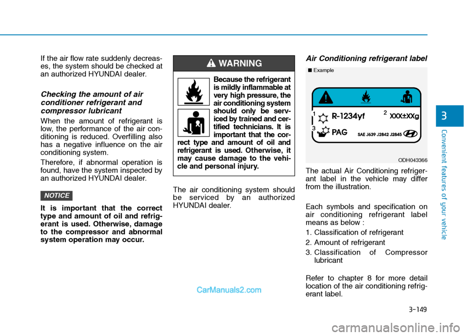
The actual Air Conditioning refriger-
ant label in the vehicle may differ
from the illustration.
Each symbols and specification on
air conditioning refrigerant label
means as below :
1. Classification of refrigerant
2. Amount of refrigerant
3. Classification of Compressor
lubricant
Refer to chapter 8 for more detail
location of the air conditioning refrig-
erant label.
NOTICE
ODH043366
■Example
Because the refrigerant
is mildly inflammable at
very high pressure, the
air conditioning system
should only be serv-
iced by trained and cer-
tified technicians. It is
important that the cor-
rect type and amount of oil and
refrigerant is used.Otherwise, it
may cause damage to the vehi-
cle and personal injury.
WARNING