2019 Hyundai Tucson crank
[x] Cancel search: crankPage 273 of 546

5-7
Driving your vehicle
5
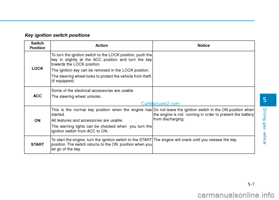
Key ignition switch positions
Switch
PositionActionNotice
LOCK
To turn the ignition switch to the LOCK position, push the
key in slightly at the ACC position and turn the key
towards the LOCK position.
The ignition key can be removed in the LOCK position.
The steering wheel locks to protect the vehicle from theft.
(if equipped)
ACC
Some of the electrical accessories are usable.
The steering wheel unlocks.
ON
This is the normal key position when the engine has
started.
All features and accessories are usable.
The warning lights can be checked when you turn the
ignition switch from ACC to ON.Do not leave the ignition switch in the ON position when
the engine is not running in order to prevent the battery
from discharging.
START
To start the engine, turn the ignition switch to the START
position. The switch returns to the ON position when you
let go of the key.The engine will crank until you release the key.
Page 436 of 546

7
Tire Traction .....................................................................7-41
Tire Maintenance ............................................................7-41
Tire Sidewall Labeling ....................................................7-41
Tire Terminology and Definitions................................7-45
All Season Tires ...............................................................7-48
Summer Tires ...................................................................7-48
Snow Tires ........................................................................7-49
Radial-Ply Tires ...............................................................7-49
Low Aspect Ratio Tires..................................................7-50
Fuses ......................................................................7-51
Instrument Panel Fuse Replacement..........................7-52
Engine Compartment Panel Fuse Replacement.......7-53
Fuse/Relay Panel Description ......................................7-56
Light Bulbs ............................................................7-64
Headlamp, Daytime Running Lamp, Side Marker,
Parking Lamp, Turn Signal Lamp and
Fog Lamp Replacement .................................................7-65
Side Repeater Lamp Replacement ..............................7-69
Rear Combination Light Bulb Replacement ..............7-70
High Mounted Stop Lamp Replacement ....................7-73
License Plate Light Bulb Replacement ......................7-73
Interior Light Bulb Replacement .................................7-73
Appearance Care..................................................7-75
Exterior Care ....................................................................7-75
Interior Care .....................................................................7-80
Emission Control System ....................................7-83
Crankcase Emission Control System ..........................7-83
Evaporative Emission Control System Including
Onboard Refueling Vapor Recovery (ORVR)............7-83
Exhaust Emission Control System ..............................7-84
California Perchlorate Notice.............................7-87
Page 448 of 546

7-14
Maintenance
E EX
XP
PL
LA
AN
NA
AT
TI
IO
ON
N
O
OF
F
S
SC
CH
HE
ED
DU
UL
LE
ED
D
M
MA
AI
IN
NT
TE
EN
NA
AN
NC
CE
E
I
IT
TE
EM
MS
S
Engine Oil and Filter
The engine oil and filter should be
changed at the intervals specified in
the maintenance schedule. If the car
is being driven in severe conditions,
more frequent oil and filter changes
are required.
Drive Belts
Inspect all drive belts for evidence of
cuts, cracks, excessive wear or oil
saturation and replace if necessary.
Drive belts should be checked peri-
odically for proper tension and
adjusted as necessary.
Fuel Filter
A clogged-up fuel filter may limit the
vehicle driving speed, damage the
emission system, and cause the
hard starting. When a considerable
amount of foreign substances are
accumulated in the fuel tank, the fuel
filter should be replaced.Upon installing a new fuel filter, oper-
ate the diesel engine for several min-
utes, and check the connections for
any leakages. Fuel filters should be
installed by an authorized HYUNDAI
dealer.
Fuel Lines, Fuel Hoses and
Connections
Check the fuel lines, fuel hoses and
connections for leakage and dam-
age. Have an authorized HYUNDAI
dealer replace any damaged or leak-
ing parts immediately.
Vapor Hose and Fuel Filler
Cap
The vapor hose and fuel filler cap
should be inspected at those inter-
vals specified in the maintenance
schedule. Make sure a new vapor
hose or fuel filler cap is correctly
replaced.
Vacuum Crankcase Ventilation
Hoses (if equipped)
Inspect the surface of hoses for evi-
dence of heat and/or mechanical
damage. Hard and brittle rubber,
cracking, tears, cuts, abrasions, and
excessive swelling indicate deterio-
ration. Particular attention should be
paid to examine those hose surfaces
nearest to high heat sources, such
as the exhaust manifold.
Inspect the hose routing to assure
that the hoses do not come in con-
tact with any heat source, sharp
edges or moving component which
might cause heat damage or
mechanical wear. Inspect all hose
connections, such as clamps and
couplings, to make sure they are
secure, and that no leaks are pres-
ent. Hoses should be replaced
immediately if there is any evidence
of deterioration or damage.
Page 517 of 546

7-83
7
Maintenance
E EM
MI
IS
SS
SI
IO
ON
N
C
CO
ON
NT
TR
RO
OL
L
S
SY
YS
ST
TE
EM
M
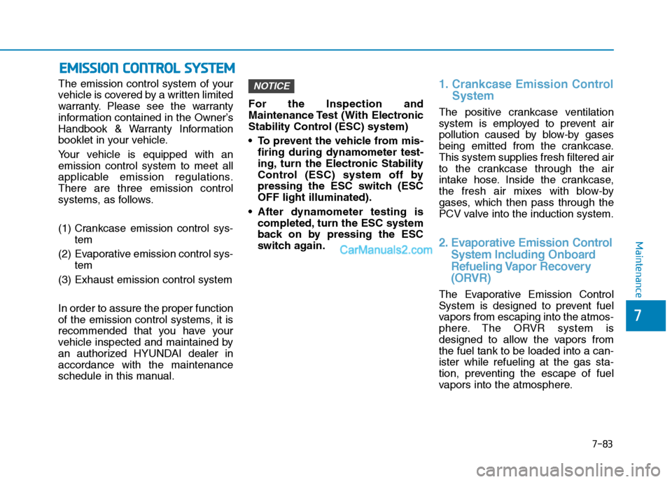
The emission control system of your
vehicle is covered by a written limited
warranty. Please see the warranty
information contained in the Owner’s
Handbook & Warranty Information
booklet in your vehicle.
Your vehicle is equipped with an
emission control system to meet all
applicable emission regulations.
There are three emission control
systems, as follows.
(1) Crankcase emission control sys-
tem
(2) Evaporative emission control sys-
tem
(3) Exhaust emission control system
In order to assure the proper function
of the emission control systems, it is
recommended that you have your
vehicle inspected and maintained by
an authorized HYUNDAI dealer in
accordance with the maintenance
schedule in this manual.For the Inspection and
Maintenance Test (With Electronic
Stability Control (ESC) system)
To prevent the vehicle from mis-
firing during dynamometer test-
ing, turn the Electronic Stability
Control (ESC) system off by
pressing the ESC switch (ESC
OFF light illuminated).
After dynamometer testing is
completed, turn the ESC system
back on by pressing the ESC
switch again.1. Crankcase Emission Control
System
The positive crankcase ventilation
system is employed to prevent air
pollution caused by blow-by gases
being emitted from the crankcase.
This system supplies fresh filtered air
to the crankcase through the air
intake hose. Inside the crankcase,
the fresh air mixes with blow-by
gases, which then pass through the
PCV valve into the induction system.
2. Evaporative Emission Control
System Including Onboard
Refueling Vapor Recovery
(ORVR)
The Evaporative Emission Control
System is designed to prevent fuel
vapors from escaping into the atmos-
phere. The ORVR system is
designed to allow the vapors from
the fuel tank to be loaded into a can-
ister while refueling at the gas sta-
tion, preventing the escape of fuel
vapors into the atmosphere.
NOTICE
Page 539 of 546

I-4
Driver Attention Warning (DAW) System......................5-96
Resetting the System ..................................................5-97
System Malfunction ...................................................5-98
System Setting and Activation ...................................5-96
System Standby ..........................................................5-98
Driver's front air bag .......................................................2-50
Electric Power Steering (EPS) ........................................3-21
Electronic Parking Brake (EPB) .....................................5-24
Electronic Stability Control (ESC) .................................5-35
Emission Control System ...............................................7-83
Crankcase Emission Control System .........................7-83
Evaporative Emission Control System Including
Onboard Refueling Vapor Recovery (ORVR) ........7-83
Exhaust Emission Control System .............................7-84
Engine ...............................................................................8-2
Engine compartment..................................................1-6, 7-3
Engine Coolant ...............................................................7-19
Changing Engine Coolant ..........................................7-22
Checking the Engine Coolant Level ..........................7-19
Engine Number ...............................................................8-12
Engine Oil .......................................................................7-17
Checking the Engine Oil and Filter ...........................7-18
Checking the Engine Oil Level ..................................7-17
Explanation Of Scheduled Maintenance Items ..............7-14Exterior Features .................................................3-47, 3-171
Fuel Filler Door ..........................................................3-48
Hood ...........................................................................3-47
Roof Rack.................................................................3-171
Exterior Lights ..............................................................3-107
AUTO headlamp position ........................................3-108
Battery saver function ..............................................3-114
Daytime running light (DRL) ..................................3-107
Front fog lamp ..........................................................3-114
Headlamp delay function..........................................3-115
Headlamp position....................................................3-109
High Beam Assist (HBA) .........................................3-110
High beam operation ................................................3-109
Lane change signals..................................................3-113
Parking lamp position ..............................................3-108
Turn signals ..............................................................3-113
Exterior overview .............................................................1-2
Floor Mat Anchor(s) .....................................................3-166
Forward Collision-Avoidance Assist (FCA) System
- Camera Type .............................................................5-60
FCA Sensor ................................................................5-65
FCA Warning Message and System Control..............5-63
Limitations of the System ..........................................5-68
System Not Operating ................................................5-67
System Setting and Activation ...................................5-60
Index
E
F