Page 466 of 557
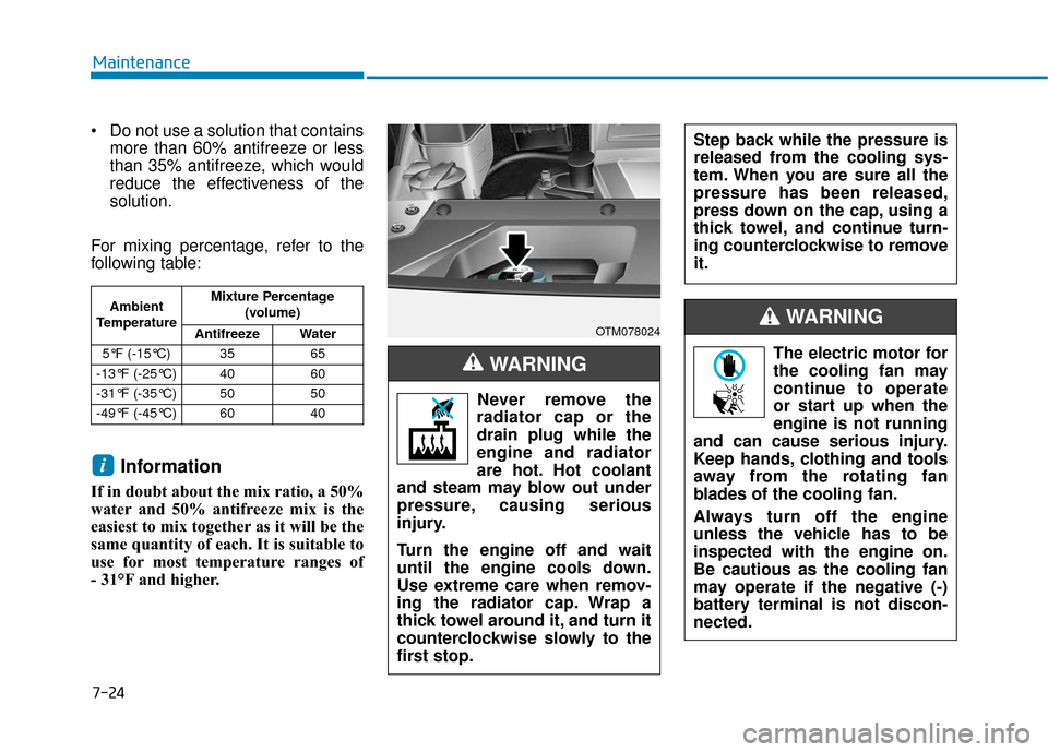
Do not use a solution that containsmore than 60% antifreeze or less
than 35% antifreeze, which would
reduce the effectiveness of the
solution.
For mixing percentage, refer to the
following table:
Information
If in doubt about the mix ratio, a 50%
water and 50% antifreeze mix is the
easiest to mix together as it will be the
same quantity of each. It is suitable to
use for most temperature ranges of
- 31°F and higher.
i
7-24
Maintenance
The electric motor for
the cooling fan may
continue to operate
or start up when the
engine is not running
and can cause serious injury.
Keep hands, clothing and tools
away from the rotating fan
blades of the cooling fan.
Always turn off the engine
unless the vehicle has to be
inspected with the engine on.
Be cautious as the cooling fan
may operate if the negative (-)
battery terminal is not discon-
nected.
WARNING Ambient
Temperature Mixture Percentage
(volume)
Antifreeze Water
5°F (-15°C) 35 65
-13°F (-25°C) 40 60
-31°F (-35°C) 50 50
-49°F (-45°C) 60 40
Never remove the
radiator cap or the
drain plug while the
engine and radiator
are hot. Hot coolant
and steam may blow out under
pressure, causing serious
injury.
Turn the engine off and wait
until the engine cools down.
Use extreme care when remov-
ing the radiator cap. Wrap a
thick towel around it, and turn it
counterclockwise slowly to the
first stop.
WARNING
OTM078024
Step back while the pressure is
released from the cooling sys-
tem. When you are sure all the
pressure has been released,
press down on the cap, using a
thick towel, and continue turn-
ing counterclockwise to remove
it.
Page 473 of 557
W
WI
IP
P E
ER
R
B
B L
LA
A D
DE
ES
S
Blade Inspection
Contamination of either the windshield
or the wiper blades with foreign matter
can reduce the effectiveness of the
windshield wiper functionality.
Common sources of contamination
are insects, tree sap, and hot wax
treatments used by some commercial
car washes. If the blades are not wip-
ing properly, clean both the window
and the blades with a clean cloth
dampened with washer fluid.
To prevent damage to the wiper
blades, arms or other compo-
nents, do not:
Use gasoline, kerosene, paint
thinner, or other solvents on or
near them.
Attempt to move the wipers manually.
Use non-specified wiper blades.
Information
Commercial hot waxes applied by auto-
matic car washes have been known to
make the windshield difficult to clean.
Blade Replacement
When the wipers no longer clean
adequately, the blades may be worn
or cracked, and require replacement.
To prevent damage to the wiper
arms or other components, do not
attempt to move the wipers manu-
ally.
The use of a non-specified wiper
blade could result in wiper mal-
function and failure.
In order to prevent damage to the hood and the wiper arms, the
wiper arms should only be lifted
when in the top wiping position.
Always return the wiper arms to the windshield before driving.
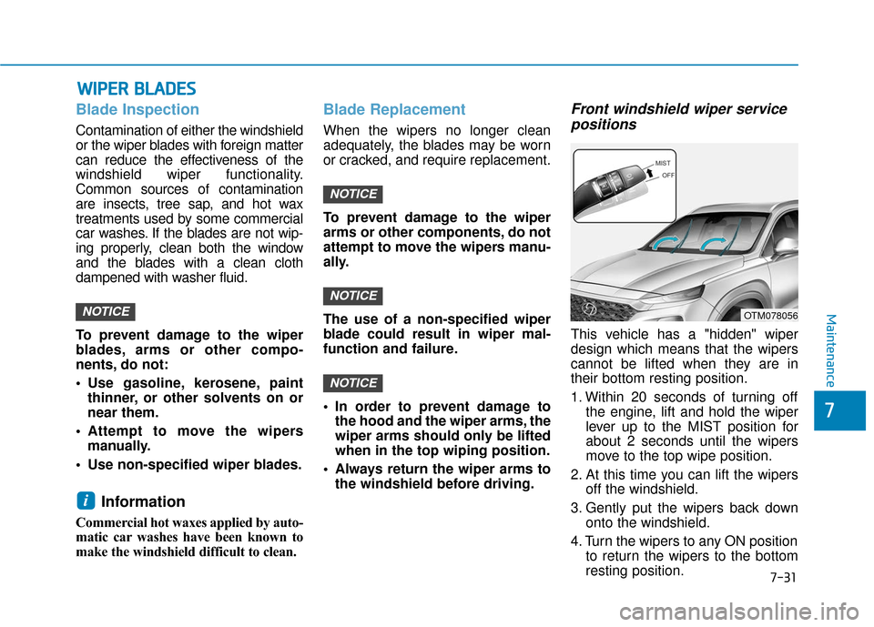
Front windshield wiper servicepositions
This vehicle has a "hidden" wiper
design which means that the wipers
cannot be lifted when they are in
their bottom resting position.
1. Within 20 seconds of turning off
the engine, lift and hold the wiper
lever up to the MIST position for
about 2 seconds until the wipers
move to the top wipe position.
2. At this time you can lift the wipers off the windshield.
3. Gently put the wipers back down onto the windshield.
4. Turn the wipers to any ON position to return the wipers to the bottom
resting position.
NOTICE
NOTICE
NOTICE
i
NOTICEOTM078056Maintenance
7
7-31
Page 474 of 557
Front windshield wiper bladereplacement
1. Put the front windshield wipers
into the service position.
2. Rotate the wiper blade assembly to expose the plastic locking clip.
Do not allow the wiper arm to fall
against the windshield, since it
may chip or crack the windshield. 3. Press the clip (1) and slide the
blade assembly downward (2).
4. Lift it off the arm.
5. Install the blade assembly in the reverse order of removal.
6. Return the wiper arm on the wind- shield.
Rear window wiper bladereplacement
1. Raise the wiper arm and then
rotate the wiper blade assembly
(1).
2. Pull out the wiper blade assembly (2).
NOTICE
OLMB073021
OLMB073022
OLMB073020
OOSEV078007
Maintenance
7-32
Page 475 of 557
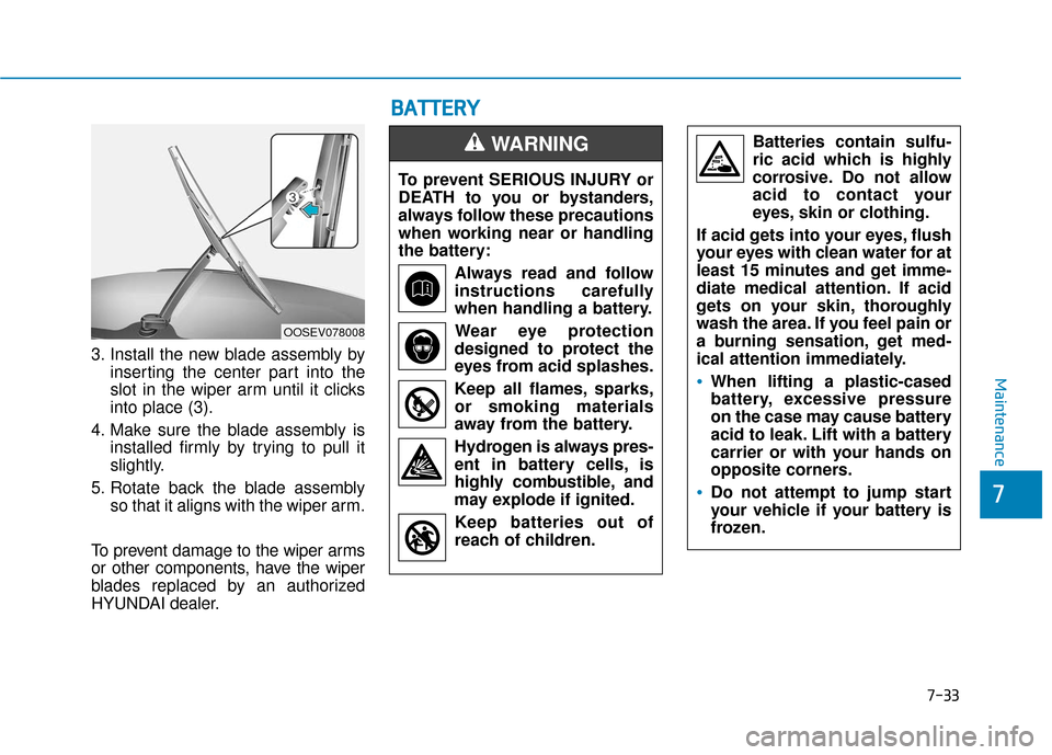
3. Install the new blade assembly byinserting the center part into the
slot in the wiper arm until it clicks
into place (3).
4. Make sure the blade assembly is installed firmly by trying to pull it
slightly.
5. Rotate back the blade assembly so that it aligns with the wiper arm.
To prevent damage to the wiper arms
or other components, have the wiper
blades replaced by an authorized
HYUNDAI dealer.
OOSEV078008
B
B A
A T
TT
TE
ER
R Y
Y
To prevent SERIOUS INJURY or
DEATH to you or bystanders,
always follow these precautions
when working near or handling
the battery:
Always read and follow
instructions carefully
when handling a battery.Wear eye protection
designed to protect the
eyes from acid splashes.
Keep all flames, sparks,
or smoking materials
away from the battery.
Hydrogen is always pres- ent in battery cells, is
highly combustible, and
may explode if ignited.
Keep batteries out of
reach of children.
WARNING Batteries contain sulfu-
ric acid which is highly
corrosive. Do not allow
acid to contact your
eyes, skin or clothing.
If acid gets into your eyes, flush
your eyes with clean water for at
least 15 minutes and get imme-
diate medical attention. If acid
gets on your skin, thoroughly
wash the area. If you feel pain or
a burning sensation, get med-
ical attention immediately.
When lifting a plastic-cased
battery, excessive pressure
on the case may cause battery
acid to leak. Lift with a battery
carrier or with your hands on
opposite corners.
Do not attempt to jump start
your vehicle if your battery is
frozen.
Maintenance
7
7-33
Page 494 of 557
F
FU
U S
SE
E S
S
A vehicle's electrical system is pro-
tected from electrical overload dam-
age by fuses.
This vehicle has 2 (or 3) fuse panels,
one located in the driver's side panel
bolster, the other in the engine com-
partment near the battery.
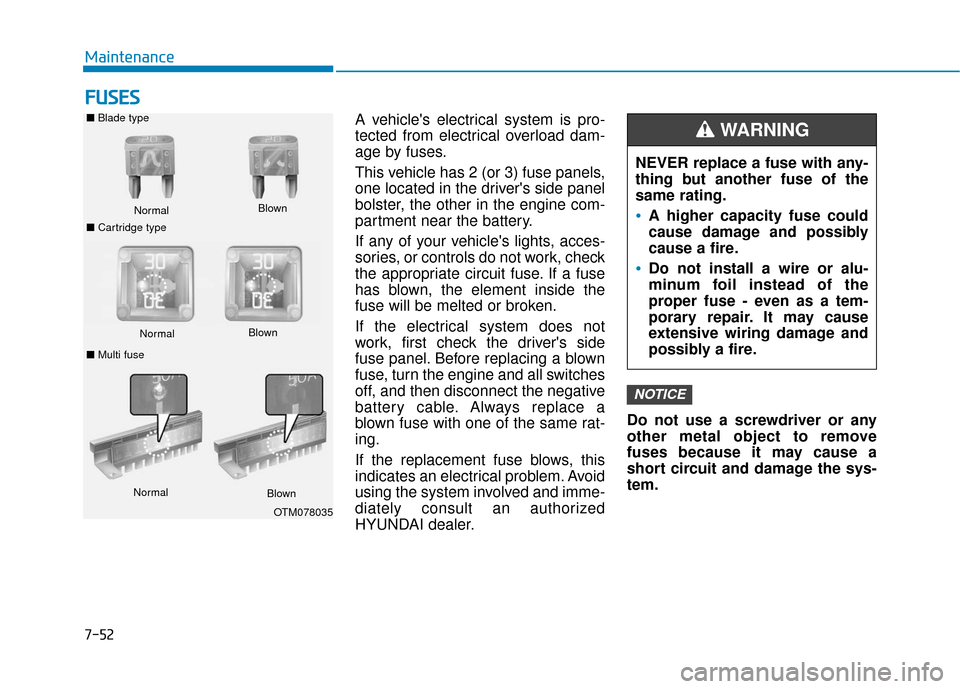
If any of your vehicle's lights, acces-
sories, or controls do not work, check
the appropriate circuit fuse. If a fuse
has blown, the element inside the
fuse will be melted or broken.
If the electrical system does not
work, first check the driver's side
fuse panel. Before replacing a blown
fuse, turn the engine and all switches
off, and then disconnect the negative
battery cable. Always replace a
blown fuse with one of the same rat-
ing.
If the replacement fuse blows, this
indicates an electrical problem. Avoid
using the system involved and imme-
diately consult an authorized
HYUNDAI dealer. Do not use a screwdriver or any
other metal object to remove
fuses because it may cause a
short circuit and damage the sys-
tem.
NOTICE
NEVER replace a fuse with any-
thing but another fuse of the
same rating.
A higher capacity fuse could
cause damage and possibly
cause a fire.
Do not install a wire or alu-
minum foil instead of the
proper fuse - even as a tem-
porary repair. It may cause
extensive wiring damage and
possibly a fire.
WARNING ■
Blade type
Normal
■ Cartridge type Blown
Normal
Blown
■ Multi fuse
Normal Blown
OTM078035
Maintenance
7-52
Page 496 of 557
7-54
Maintenance
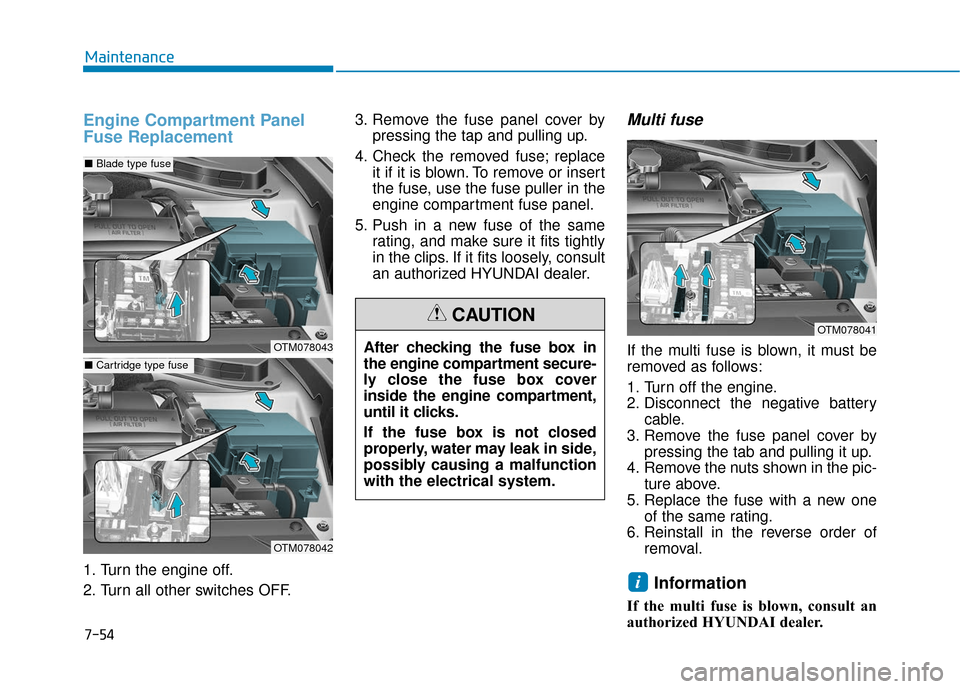
Engine Compartment Panel
Fuse Replacement
1. Turn the engine off.
2. Turn all other switches OFF.3. Remove the fuse panel cover by
pressing the tap and pulling up.
4. Check the removed fuse; replace it if it is blown. To remove or insert
the fuse, use the fuse puller in the
engine compartment fuse panel.
5. Push in a new fuse of the same rating, and make sure it fits tightly
in the clips. If it fits loosely, consult
an authorized HYUNDAI dealer.
Multi fuse
If the multi fuse is blown, it must be
removed as follows:
1. Turn off the engine.
2. Disconnect the negative batterycable.
3. Remove the fuse panel cover by pressing the tab and pulling it up.
4. Remove the nuts shown in the pic- ture above.
5. Replace the fuse with a new one of the same rating.
6. Reinstall in the reverse order of removal.
Information
If the multi fuse is blown, consult an
authorized HYUNDAI dealer.
i
OTM078041
After checking the fuse box in
the engine compartment secure-
ly close the fuse box cover
inside the engine compartment,
until it clicks.
If the fuse box is not closed
properly, water may leak in side,
possibly causing a malfunction
with the electrical system.
CAUTION
OTM078043
OTM078042
■Blade type fuse
■Cartridge type fuse
Page 512 of 557
Rear Combination Light Bulb
Replacement
Type A
(1) Stop/Tail lamp
(2) Tail lamp
(3) Side marker
(4) Turn signal lamp
(5) Backup lamp
Stop/Tail lamp and side marker
lamp
1. Turn off the engine.
2. Open the liftgate.
3. Remove the cover using a flat-blade screwdriver. 4. Loosen the lamp assembly retain-
ing screws with a cross-tip screw-
driver.
5. Remove the rear combination lamp assembly from the body of
the vehicle.
OTM078006
OTMA078004
OTM078005
Maintenance
7-70
Page 513 of 557
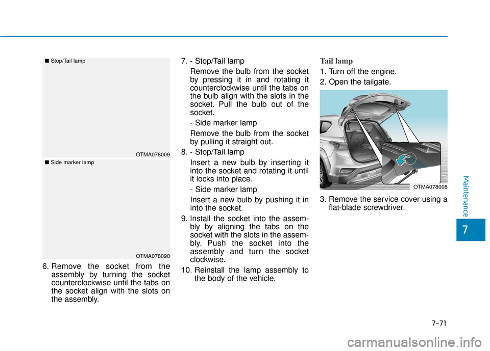
6. Remove the socket from theassembly by turning the socket
counterclockwise until the tabs on
the socket align with the slots on
the assembly. 7. - Stop/Tail lamp
Remove the bulb from the socket
by pressing it in and rotating it
counterclockwise until the tabs on
the bulb align with the slots in the
socket. Pull the bulb out of the
socket.
- Side marker lamp
Remove the bulb from the socket
by pulling it straight out.
8. - Stop/Tail lamp Insert a new bulb by inserting it
into the socket and rotating it until
it locks into place.- Side marker lamp
Insert a new bulb by pushing it in
into the socket.
9. Install the socket into the assem- bly by aligning the tabs on the
socket with the slots in the assem-
bly. Push the socket into the
assembly and turn the socket
clockwise.
10. Reinstall the lamp assembly to the body of the vehicle.
Tail lamp
1. Turn off the engine.
2. Open the tailgate.
3. Remove the service cover using aflat-blade screwdriver.
OTMA078008
OTMA078009
■
Stop/Tail lamp
OTMA078090
■
Side marker lamp
Maintenance
7-71
7