2019 Hyundai Nexo set clock
[x] Cancel search: set clockPage 257 of 560
3-170
Convenient features of your vehicle
The wireless charging processmay temporarily stop, when tem-
perature abnormally increases
inside the wireless cellular phone
charging system. Stop the charg-
ing cellular phone and wait until
temperature falls to a certain level.
The wireless charging process may temporarily stop when there
is any metallic item, such as a
coin, between the wireless cellular
phone charging system and the
cellular phone.
When charging some cellular phones with a self-protection fea-
ture, the wireless charging speed
may decrease and the wireless
charging may stop.
If the cellular phone has a thick cover, the wireless charging may
not be possible.
If the cell phone is not completely contacting the charging pad, wire-
less charging may not operate
properly.
Some magnetic items like credit cards, phone cards or rail tickets
may be damaged if left with the
cellular phone during the charging
process. When any cellular phone without a
wireless charging function or a
metallic object is placed on the
charging pad, a small noise may
sound. This small sound is due to
the vehicle discerning compatibil-
ity of the object placed on the
charging pad. It does not affect
your vehicle or the cellular phone
in any way.
Information
If the POWER button is in the OFF
position, the charging also stops.
Information
This device complies with part 15 of
the FCC Rules.
Operation is subject to the following
two conditions:
1. This device may not cause harmful interference, and
2. This device must accept any inter- ference received, including interfer-
ence that may cause undesired
operation.
Clock
Select the Vehicle Settings menu on
the AVN screen ➟Select [Date/Time].
GPS time: Displays time according to the received GNSS time.
Daylight saving time : The clock is adjusted forward one hour.
Time format : Switches to 12 hour or 24 hour.
For more details, refer to the sepa-
rately supplied Navigation manual.
i
i
Do not attempt to adjust the
clock while driving. Doing so
may result in distracted driving
which may lead to an accident
involving personal injury or
death.
WARNING
Page 403 of 560
6-6
What to do in an emergency
The following items may need to be
reset after the battery has been dis-
charged or the battery has been dis-
connected. See chapter 3 or 4 for:
Power Windows
Trip Computer
Climate Control System
Clock
Audio System
Sunroof
Driver Position Memory System
External power source using 12V
battery
The use of external power acces-
sories may reduce performance
and function of the vehicle.
Especially, the use of dash cam-
eras may shut off the power of the
vehicle prior to the dash camera's
automatic shut-down.
If the power of the vehicle is shut
off, start the vehicle as explained.
(refer to "Using the 12V Battery
Switch")
Jump Starting
In the event vehicle still does not
have a functional 12V battery (check
if interior lights will not turn on) then
you can try a jump start using a 12V
booster pack or jumper cables from
another vehicle's 12V battery
according to the following instruc-
tions. 1. Position the vehicles close enough
that the jumper cables will reach,
but do not allow the vehicles to
touch.
2. Avoid fans or any moving parts in the fuel cell power module com-
partment at all times, even when
the vehicles are turned off.
3. Turn off all electrical devices such as radios, lights, air conditioning,
etc. Put the vehicles in P (Park)
and set the parking brake. Turn
both vehicles OFF.
NOTICE
Jump starting can be danger-
ous if done incorrectly. Follow
the jump starting procedure in
this section to avoid serious
injury or damage to your vehi-
cle. If in doubt about how to
properly jump start your vehi-
cle, we strongly recommend
that you have a service techni-
cian or towing service do it for
you.
CAUTION
Page 406 of 560
6-9
What to do in an emergency
1. Pull off the road and stop as soonas it is safe to do so.
2. Shift to P (Park) and set the park- ing brake. If the air conditioning is
on, turn it off.
3. If coolant is running out under the vehicle or steam is coming out
from the hood, stop the vehicle.
Do not open the hood until the
coolant has stopped running or
the steaming has stopped. If there
is no visible loss of coolant and no
steam, leave the vehicle running
and check to be sure the vehicle
cooling fan is operating. If the fan
is not running, turn the vehicle off. 4. Check for coolant leaking from the
radiator, hoses or under the vehi-
cle. (If the air conditioning had
been in use, it is normal for cold
water to be draining from it when
you stop.)
5. If coolant is leaking out, stop the vehicle immediately and call the
nearest authorized HYUNDAI
dealer for assistance.
I IF
F
T
T H
H E
E
V
V E
EH
H I
IC
C L
LE
E
O
O V
VE
ER
R H
H E
EA
A T
TS
S
6
While the vehicle is
running, keep hands,
clothing and tools
away from the mov-
ing parts such as the
cooling fan to prevent
serious injury.
WARNING
Your vehicle is
equipped with a pres-
surized coolant
reserve tank. NEVER
remove the coolant
reserve tank cap or the radiator
drain plug while the radiator is
HOT. Hot coolant and steam
may blow out under pressure,
causing serious injury.
Turn the vehicle off and wait
until the vehicle cools down.
Use extreme care when remov-
ing the coolant reserve tank
cap. Wrap a towel or thick rag
around it, and turn it counter-
clockwise slowly to release
some of the pressure from the
system. Step back while the
pressure is released.
When you are sure all the pres-
sure has been released, contin-
ue turning the cap counter-
clockwise to remove it.
WARNING
Page 452 of 560
7-28
Maintenance
Battery recharging
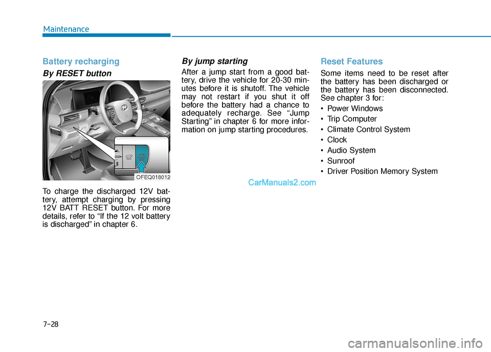
By RESET button
To charge the discharged 12V bat-
tery, attempt charging by pressing
12V BATT RESET button. For more
details, refer to “If the 12 volt battery
is discharged” in chapter 6.
By jump starting
After a jump start from a good bat-
tery, drive the vehicle for 20-30 min-
utes before it is shutoff. The vehicle
may not restart if you shut it off
before the battery had a chance to
adequately recharge. See “Jump
Starting” in chapter 6 for more infor-
mation on jump starting procedures.
Reset Features
Some items need to be reset after
the battery has been discharged or
the battery has been disconnected.
See chapter 3 for:
Power Windows
Trip Computer
Climate Control System
Clock
Audio System
Sunroof
Driver Position Memory System
OFEQ018012
Page 555 of 560
I-6
Instrument Cluster...........................................................3-58Instrument Cluster Control .........................................3-59
Gauges and Meters .....................................................3-59
Warning and Indicator Lights.....................................3-65
LCD Display Messages ..............................................3-76
Instrument Panel Overview ..............................................1-5
Interior Care ....................................................................7-67\
Interior Features ............................................................3-163 Cup Holder ...............................................................3-163
Sunvisor ....................................................................3-16\
4
Power Outlet.............................................................3-165
AC Inverter...............................................................3-166
USB Charger ............................................................3-168
Wireless Cellular Phone Charging System ..............3-168
Clock ........................................................................\
3-170
Coat Hook ................................................................3-171
Floor Mat Anchor(s) .................................................3-171
Luggage Net Holder .................................................3-172
Cargo Security Screen ..............................................3-173
Interior Overview..............................................................1-4
Introduction of FCEV .......................................................H2 Lane Following Assist (LFA) System ............................5-87
LFA operation .............................................................5-88
Warning message........................................................5-90
Limitations of the system ...........................................5-92
Lane Keeping Assist (LKA) System ..............................5-79 LKA System Operation ..............................................5-80
Warning Light and Message.......................................5-83
Limitations of the System ..........................................5-85
LKA System Function Change ..................................5-86
LCD Display ...................................................................3-81 LCD Display Control .................................................3-81
LCD Display Modes ..................................................3-82
LCD Display Messages (FCEV) .....................................H16
Leading Vehicle Departure Alert ..................................5-116 System Setting and Activation .................................5-116
Light bulbs ......................................................................7-\
57 Headlamp, front center lamp, turn signal lamp, daytime running lamp, parking lamp,
side marker replacement .........................................7-58
Side Repeater Lamp Replacement .............................7-58
Rear Combination Light Bulb Replacement ..............7-59
High mounted stop lamp ............................................7-59
License Plate Light Bulb Replacement ......................7-60
Interior Light Bulb Replacement ...............................7-60
Index
L