2019 Hyundai Kona Fuel door
[x] Cancel search: Fuel doorPage 14 of 485
1-3
Your vehicle at a glance
1
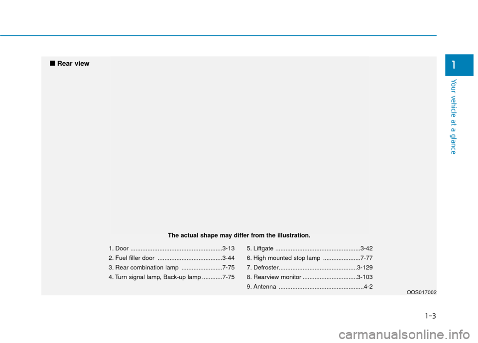
1. Door ......................................................3-13
2. Fuel filler door ......................................3-44
3. Rear combination lamp ........................7-75
4. Turn signal lamp, Back-up lamp ............7-755. Liftgate ..................................................3-42
6. High mounted stop lamp ......................7-77
7. Defroster..............................................3-129
8. Rearview monitor ................................3-103
9. Antenna ..................................................4-2
OOS017002
■
■
Rear view
The actual shape may differ from the illustration.
Page 85 of 485
Convenient features of your vehicle
Accessing Your Vehicle .........................................3-3
Remote Key........................................................................\
.3-3
Smart Key ........................................................................\
....3-6
Immobilizer System .........................................................3-11
Door Locks ............................................................3-13
Operating Door Locks from Outside the Vehicle ....3-13
Operating Door Locks from Inside the Vehicle .......3-14
Automatic Door Lock and Unlock Features .............3-17
Child-Protector Rear Door Locks ...............................3-17
Theft-Alarm System ............................................3-18
Steering Wheel .....................................................3-19
Electric Power Steering (EPS) .....................................3-19
Tilt Steering / Telescope Steering ..............................3-20
Horn ........................................................................\
............3-20
Heated Steering Wheel (for Canada) .........................3-21
Mirrors ...................................................................3-21
Inside Rearview Mirror ..................................................3-21
Side View Mirrors ...........................................................3-31
Windows ................................................................3-33
Power Windows ...............................................................3-34
Sunroof..................................................................3-37
Sunroof opening and closing .......................................3-38
Sliding the sunroof .........................................................3-38
Tilting the sunroof ..........................................................3-38
Sunshade ........................................................................\
...3-39Resetting the sunroof ....................................................3-39
Sunroof Open Warning ..................................................3-40
Exterior Features .................................................3-41
Hood ........................................................................\
...........3-41
Liftgate ........................................................................\
......3-42
Fuel Filler Door ................................................................3-44
Instrument Cluster ...............................................3-47
Instrument Cluster Control............................................3-48
Gauges and Meters ........................................................3-49
Transmission shift indicator .........................................3-52
Warning and Indicator Lights .......................................3-53
LCD Display Messages ...................................................3-65
LCD Display ...........................................................3-70
LCD Display Control ........................................................3-70
LCD Display Modes .........................................................3-71
Trip Computer .......................................................3-81
Head Up Display (HUD) .......................................3-85
Lighting..................................................................3-88
Exterior Lights .................................................................3-88
Smart cornering lamp ....................................................3-95
Interior Lights...................................................................3-96
Welcome System .............................................................3-98
3
Page 128 of 485
3-44
Convenient features of your vehicle
2. Slide the key or screwdriver to the right to engage the safety release
lever.
3. Push the liftgate outward and upward.
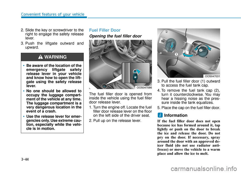
Fuel Filler Door
Opening the fuel filler door
The fuel filler door is opened from
inside the vehicle using the fuel filler
door release lever.
1. Turn the engine off. Locate the fuelfiller door release lever on the floor
on the left side of the driver seat.
2. Pull up on the release lever. 3. Pull the fuel filler door (1) outward
to access the fuel tank cap.
4. To remove the fuel tank cap (2), turn it counterclockwise. You may
hear a hissing noise as the pres-
sure inside the tank equalizes.
5. Place the cap on the fuel filler door.
Information
If the fuel filler door does not open
because ice has formed around it, tap
lightly or push on the door to break
the ice and release the door. Do not
pry on the door. If necessary, spray
around the door with an approved de-
icer fluid (do not use radiator anti-
freeze) or move the vehicle to a warm
place and allow the ice to melt.
i
Be aware of the location of the
emergency liftgate safety
release lever in your vehicle
and know how to open the lift-
gate using the safety release
lever.
No one should be allowed to
occupy the luggage compart-
ment of the vehicle at any time.
The luggage compartment is a
very dangerous location in the
event of a crash.
Use the release lever for emer-
gencies only. Use extreme cau-
tion, especially while the vehi-
cle is in motion.
WARNING
OOS047086
OOS047031
Page 129 of 485
3-45
Convenient features of your vehicle
3
Closing the fuel filler door
1. To install the fuel tank cap, turn itclockwise until it "clicks" one time.
2. Close the fuel filler door until it is latched securely.Do not get back into a vehicle
once you have begun refuel-
ing. You can generate a build-
up of static electricity by
touching, rubbing or sliding
against any item or fabric
capable of producing static
electricity. Static electricity
discharge can ignite fuel
vapors causing a fire. If you
must re-enter the vehicle, you
should once again eliminate
potentially dangerous static
electricity discharge by touch-
ing a metal part of the vehicle,
away from the fuel filler neck,
nozzle or other gasoline
source, with your bare hand.
When using an approved
portable fuel container, be
sure to place the container on
the ground prior to refueling.
Static electricity discharge
from the container can ignite
fuel vapors causing a fire.
Gasoline is highly flammable
and explosive. Failure to follow
these guidelines may result in
SERIOUS INJURY or DEATH:
Read and follow all warnings
posted at the gas station.
Before refueling, note the
location of the Emergency
Gasoline Shut-Off, if available,
at the gas station.
Before touching the fuel noz-
zle, you should eliminate the
potential build-up of static
electricity by touching a metal
part of the vehicle, a safe dis-
tance away from the fuel filler
neck, nozzle, or other gas
source, with your bare hand.
Do not use cellular phones
while refueling. Electric cur-
rent and/or electronic interfer-
ence from cellular phones can
potentially ignite fuel vapors
and cause a fire.
WARNING
Page 155 of 485
3-71
Convenient features of your vehicle
3
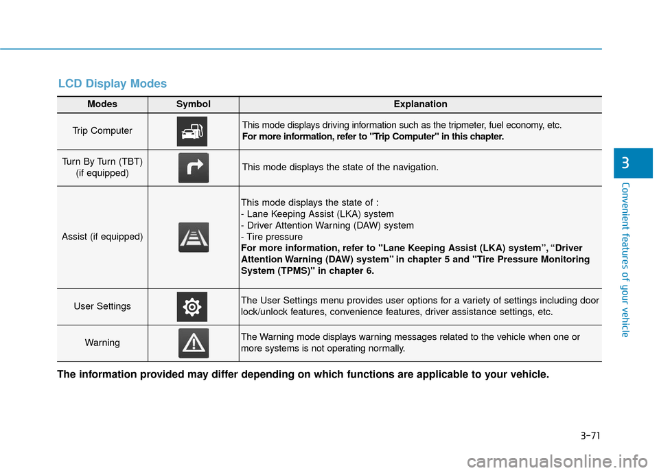
Modes SymbolExplanation
Trip Computer This mode displays driving information such as the tripmeter, fuel economy, etc.
For more information, refer to "Trip Computer" in this chapter.
Turn By Turn (TBT) (if equipped)This mode displays the state of the navigation.
Assist (if equipped)
This mode displays the state of :
- Lane Keeping Assist (LKA) system
- Driver Attention Warning (DAW) system
- Tire pressure
For more information, refer to "Lane Keeping Assist (LKA) system”, “Driver
Attention Warning (DAW) system” in chapter 5 and "Tire Pressure Monitoring
System (TPMS)" in chapter 6.
User SettingsThe User Settings menu provides user options for a variety of settings including door
lock/unlock features, convenience features, driver assistance settings, etc.
WarningThe Warning mode displays warning messages related to the vehicle when one or
more systems is not operating normally.
The information provided may differ depending on which functions are applicable to your vehicle.
LCD Display Modes
Page 337 of 485
Two labels on your driver's door sill
show how much weight your vehicle
was designed to carry: the Tire and
Loading Information Label and the
Certification Label.
Before loading your vehicle, familiar-
ize yourself with the following terms
for determining your vehicle’s weight
ratings, from the vehicle's specifica-
tions and the Certification Label:
Base Curb Weight
This is the weight of the vehicle
including a full tank of fuel and all
standard equipment. It does not
include passengers, cargo, or option-
al equipment.
Vehicle Curb Weight
This is the weight of your new vehicle
when you picked it up from your deal-
er plus any aftermarket equipment.Cargo Weight
This figure includes all weight added
to the Base Curb Weight, including
cargo and optional equipment.
GAW (Gross Axle Weight)
This is the total weight placed on
each axle (front and rear) - including
vehicle curb weight and all payload.
GAWR (Gross Axle Weight Rating)
This is the maximum allowable
weight that can be carried by a single
axle (front or rear). These numbers
are shown on the Certification Label.
The total load on each axle must
never exceed its GAWR.
GVW (Gross Vehicle Weight)
This is the Base Curb Weight plus
actual Cargo Weight plus passen-
gers.
GVWR (Gross Vehicle Weight
Rating)
This is the maximum allowable
weight of the fully loaded vehicle
(including all options, equipment,
passengers and cargo). The GVWR
is shown on the Certification Label
located on the driver’s door sill.
V V
E
EH
H I
IC
C L
LE
E
L
L O
O A
AD
D
L
L I
IM
M I
IT
T
Driving your vehicle
5-105
5
Page 341 of 485
Certification label
The certification label is located on
the driver’s door sill at the center pil-
lar and shows the maximum allow-
able weight of the fully loaded vehi-
cle. This is called the GVWR (Gross
Vehicle Weight Rating). The GVWR
includes the weight of the vehicle, all
occupants, fuel and cargo.
This label also tells you the maxi-
mum weight that can be supported
by the front and rear axles, called
Gross Axle Weight Rating (GAWR).The total weight of the vehicle,
including all occupants, accessories,
cargo, and trailer tongue load must
not exceed the Gross Vehicle Weight
Rating (GVWR) or the Gross Axle
Weight Rating (GAWR). To find out
the actual loads on your front and
rear axles, you need to go to a weigh
station and weigh your vehicle. Be
sure to spread out your load equally
on both sides of the centerline.
OBH059070
Overloading
Never exceed the GVWR for
your vehicle, the GAWR for
either the front or rear axle
and vehicle capacity weight.
Exceeding these ratings can
affect your vehicle’s handling
and braking ability, and cause
an accident.
Do not overload your vehicle.
Overloading your vehicle can
cause heat buildup in your
vehicle’s tires and possible
tire failure, increased stop-
ping distances and poor vehi-
cle handling-all of which may
result in a crash.
WARNING
Driving your vehicle
5-109
5
Page 377 of 485
7-5
7
Maintenance
O
OW
W N
NE
ER
R
M
M A
AI
IN
N T
TE
EN
N A
AN
N C
CE
E
The following lists are vehicle checks
and inspections that should be per-
formed by the owner or an author-
ized HYUNDAI dealer at the frequen-
cies indicated to help ensure safe,
dependable operation of your vehi-
cle.
Any adverse conditions should be
brought to the attention of your deal-
er as soon as possible.
These Owner Maintenance vehicle
checks are generally not covered by
warranties and you may be charged
for labor, parts and lubricants used.
Performing maintenance work
on a vehicle can be dangerous.
If you lack sufficient knowledge
and experience or the proper
tools and equipment to do the
work, have it done by an author-
ized HYUNDAI dealer.
ALWAYS follow these precau-
tions for performing mainte-
nance work:
•Park your vehicle on level
ground, move the shift lever
into the P (Park, for automatic
transmission vehicle) posi-
tion, place the ignition switch
in the LOCK/OFF position.
WARNING Block the tires (front and
back) to prevent the vehicle
from moving.
Remove loose clothing or jew-
elry that can become entan-
gled in moving parts.
If you must run the engine
during maintenance, do so
out doors or in an area with
plenty of ventilation.
Keep flames, sparks, or smok-
ing materials away from the
battery and fuel-related parts.