Page 405 of 540
7-25
7
Maintenance
By jump starting
After a jump start from a good bat-
tery, drive the vehicle for 20-30 min-
utes before it is shutoff. The vehicle
may not restart if you shut it off
before the battery had a chance to
adequately recharge. See "Jump
Starting" in chapter 6 for more infor-
mation on jump starting procedures.
Information
An inappropriately disposedbattery can be harmful to
the environment and human
health. Dispose of the bat-
tery according to your local
law(s) or regulation.
Reset Features
Some items need to be reset after
the battery has been discharged or
the battery has been disconnected.
Power Windows
Trip Computer
Climate Control System
Clock
Audio System
Sunroof
i
Watch the battery during
charging, and stop or reduce
the charging rate if the battery
cells begin boiling violently.
The negative battery cable
must be removed first and
installed last when the battery
is disconnected. Disconnect
the battery charger in the fol-
lowing order:
(1) Turn off the battery charg-
er main switch.
(2) Unhook the negative
clamp from the negative
battery terminal.
(3) Unhook the positive clamp from the positive battery
terminal.
Always use a genuine
HYUNDAI approved battery
when you replace the battery.
Page 417 of 540

7-37
7
Maintenance
Maximum Inflation Pressure
The maximum air pressure to which
a cold tire may be inflated. The max-
imum air pressure is molded onto the
sidewall.
Maximum Load Rating
The load rating for a tire at the maxi-
mum permissible inflation pressure
for that tire.
Maximum Loaded VehicleWeight
The sum of curb weight; accessory
weight; vehicle capacity weight; and
production options weight.
Normal Occupant Weight
The number of occupants a vehicle
is designed to seat multiplied by 150
pounds (68 kg).
Occupant Distribution
Designated seating positions.
Outward Facing Sidewall
An asymmetrical tire has a particular
side that faces outward when mount-
ed on a vehicle. The outward facing
sidewall bears white lettering or
bears manufacturer, brand, and/or
model name molding that is higher or
deeper than the same moldings on
the inner facing sidewall.
Passenger (P-Metric) tire
A tire used on passenger cars and
some light duty trucks and multipur-
pose vehicles.
Ply
A layer of rubber-coated parallel
cords.
Pneumatic tire
A mechanical device made of rubber,
chemicals, fabric and steel or other
materials, that, when mounted on an
automotive wheel provides the trac-
tion and contains the gas or fluid that
sustains the load.
Pneumatic options weight
The combined weight of installed
regular production options weighing
over 5 lb. (2.3 kg) in excess of the
standard items which they replace,
not previously considered in curb
weight or accessory weight, includ-
ing heavy duty breaks, ride levelers,
roof rack, heavy duty battery, and
special trim.
Recommended InflationPressure
Vehicle manufacturer's recommend-
ed tire inflation pressure as shown
on the tire placard.
Page 421 of 540
7-41
7
Maintenance
F
FU
U S
SE
E S
S
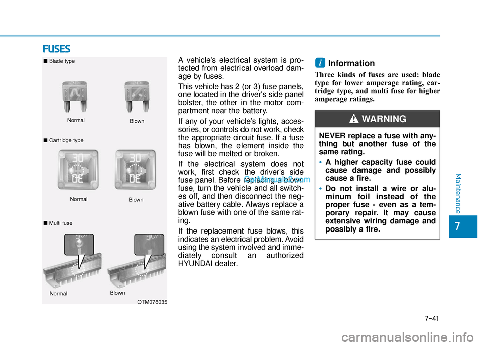
A vehicle's electrical system is pro-
tected from electrical overload dam-
age by fuses.
This vehicle has 2 (or 3) fuse panels,
one located in the driver's side panel
bolster, the other in the motor com-
partment near the battery.
If any of your vehicle’s lights, acces-
sories, or controls do not work, check
the appropriate circuit fuse. If a fuse
has blown, the element inside the
fuse will be melted or broken.
If the electrical system does not
work, first check the driver's side
fuse panel. Before replacing a blown
fuse, turn the vehicle and all switch-
es off, and then disconnect the neg-
ative battery cable. Always replace a
blown fuse with one of the same rat-
ing.
If the replacement fuse blows, this
indicates an electrical problem. Avoid
using the system involved and imme-
diately consult an authorized
HYUNDAI dealer.Information
Three kinds of fuses are used: blade
type for lower amperage rating, car-
tridge type, and multi fuse for higher
amperage ratings.
i
NEVER replace a fuse with any-
thing but another fuse of the
same rating.
A higher capacity fuse could
cause damage and possibly
cause a fire.
Do not install a wire or alu-
minum foil instead of the
proper fuse - even as a tem-
porary repair. It may cause
extensive wiring damage and
possibly a fire.
WARNING Normal
■
Blade type
■ Cartridge type Blown
Normal Blown
OTM078035
Normal
Blown
■ Multi fuse
Page 431 of 540
7-51
7
Maintenance
Motor compartment fuse panel
Fuse NameFuse RatingProtected Component
MULTI
FUSE-3MAIN150AE/R Junction Block (Fuse - IEB 1, IEB 2, CHARGER 1), EPCU (LDC)
MDPS80AMDPS Unit
MULTI
FUSE-1
B+ 560APCB Block ((Fuse - BATTERY MANAGEMENT, HORN, EPCU 1, H/LAMP), IG3 MAIN Relay)
B+ 260AIGPM ((Fuse - S/HEATER), IPS0, IPS1, IPS2)
B+ 360AIGPM (IPS3, IPS5, IPS6, IPS7, IPS8)
B+ 450AIGPM (Fuse - P/WINDOW LH, P/WINDOW RH, TAIL GATE OPEN, SUNROOF, AMP,
P/SEAT (DRV), P/SEAT (PASS))
COOLING FA N60AE/R Junction Block (Cooling Fan Relay)
REAR
HEATED40AE/R Junction Block (Rear Heated Relay)
IG140AE/R Junction Block (PDM (IG1) 2 Relay, PDM (ACC) 1 Relay)
IG240AE/R Junction Block (PDM (IG2) 3 Relay)
MULTI
FUSE-2IEB 440AElectronic Brake Control Module
BLOWER40AE/R Junction Block (Blower Relay)
Page 433 of 540
7-53
7
Maintenance
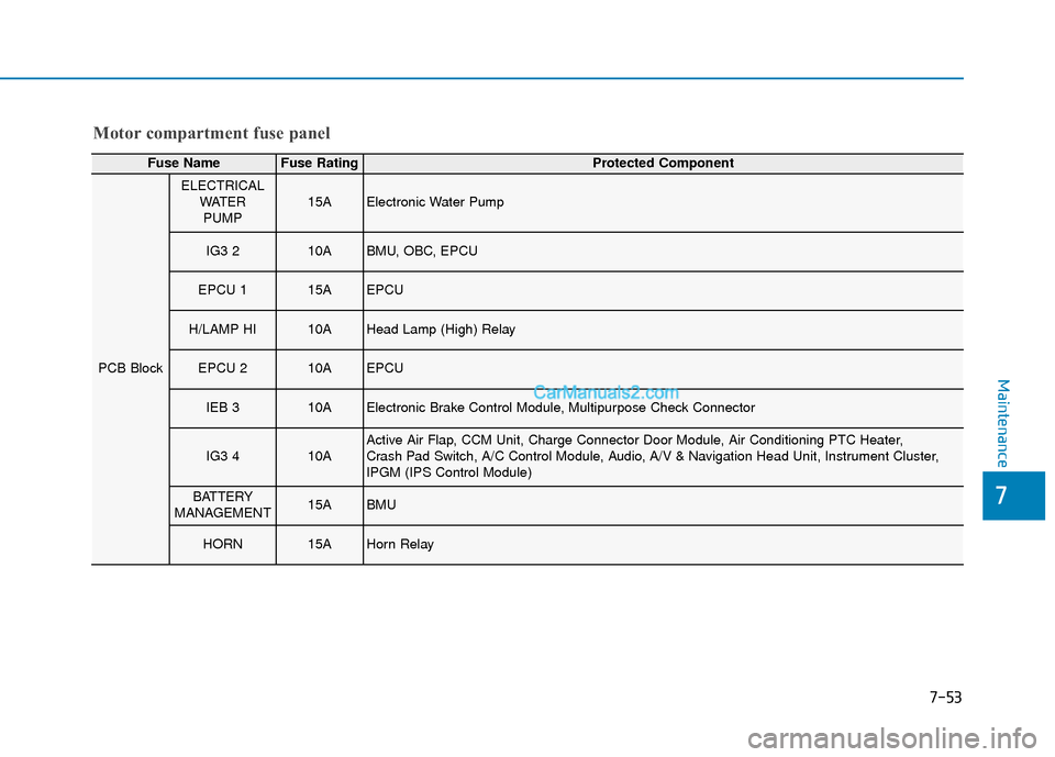
Motor compartment fuse panel
Fuse NameFuse RatingProtected Component
PCB Block
ELECTRICALWATERPUMP15AElectronic Water Pump
IG3 210ABMU, OBC, EPCU
EPCU 115AEPCU
H/LAMP HI10AHead Lamp (High) Relay
EPCU 210AEPCU
IEB 310AElectronic Brake Control Module, Multipurpose Check Connector
IG3 410AActive Air Flap, CCM Unit, Charge Connector Door Module, Air Conditioning PTC Heater,
Crash Pad Switch, A/C Control Module, Audio, A/V & Navigation Head Unit, Instrument Cluster,
IPGM (IPS Control Module)
BATTERY
MANAGEMENT15ABMU
HORN15AHorn Relay
Page 434 of 540
7-54
Maintenance
Motor compartment fuse panel(Battery terminal cover)
Inside the fuse/relay box cover, you
can find the fuse/relay label describ-
ing fuse/relay name and capacity.
Information
Not all fuse panel descriptions in this
manual may be applicable to your
vehicle; the information is accurate at
the time of printing. When you inspect
the fuse panel in your vehicle, refer to
the fuse panel label.
i
OOSEV078019
OPD076065
After checking the fuse panel in the motor compartment, securely
install the cover. If it is not securely latched, electrical failure may occur
from water contact.
NOTICE
Page 436 of 540
7-56
Maintenance
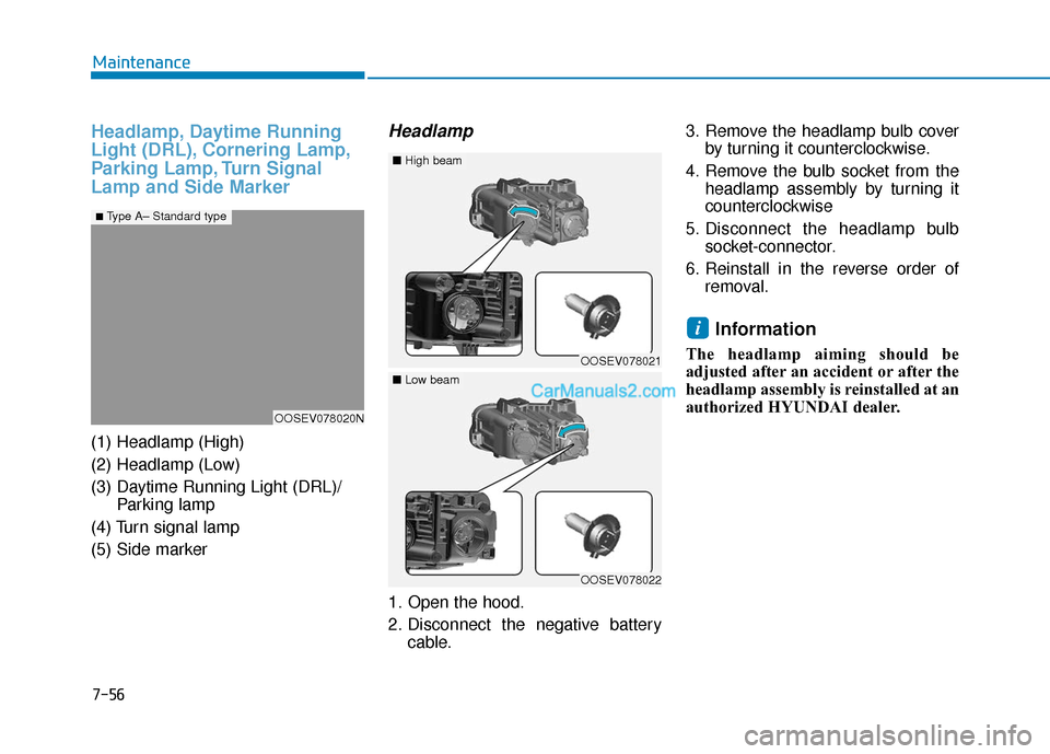
Headlamp, Daytime Running
Light (DRL), Cornering Lamp,
Parking Lamp, Turn Signal
Lamp and Side Marker
(1) Headlamp (High)
(2) Headlamp (Low)
(3) Daytime Running Light (DRL)/Parking lamp
(4) Turn signal lamp
(5) Side marker
Headlamp
1. Open the hood.
2. Disconnect the negative battery cable. 3. Remove the headlamp bulb cover
by turning it counterclockwise.
4. Remove the bulb socket from the headlamp assembly by turning it
counterclockwise
5. Disconnect the headlamp bulb socket-connector.
6. Reinstall in the reverse order of removal.
Information
The headlamp aiming should be
adjusted after an accident or after the
headlamp assembly is reinstalled at an
authorized HYUNDAI dealer.
i
OOSEV078020N
■ Type A– Standard type
OOSEV078021
■High beam
OOSEV078022
■Low beam
Page 437 of 540

7-57
7
Maintenance
Always handle them carefully, andavoid scratches and abrasions. If
the bulbs are lit, avoid contact with
liquids.
Never touch the glass with bare hands. Residual oil may cause the
bulb to overheat and burst when lit.
A bulb should be operated only when installed in a headlamp.
If a bulb becomes damaged or cracked, replace it immediately
and carefully dispose of it.
Daytime running light(DRL)/Position lamp
If the lamp (LED) does not operate,
have the system checked by an
authorized HYUNDAI dealer.
The LED lamps cannot be replaced
as a single unit because it is an inte-
grated unit. The LED lamps has to be
replaced with the unit.
A skilled technician should check or
repair the LED lamp, for it may dam-
age related parts of the vehicle.
Turn signal lamp
1. Open the hood.
2. Disconnect the negative battery
cable.
3. Remove the socket from the assembly by turning the socket
counterclockwise until the tabs on
the socket align with the slots on
the assembly.
4. Remove the bulb from the socket by pressing it in and rotating it
counterclockwise until the tabs on
the bulb align with the slots in the
socket. Pull the bulb out of the
socket.
OOSEV078023Halogen bulb
Handle halogen bulbs with
care. Halogen bulbs contain
pressurized gas that will pro-
duce flying pieces of glass
that could cause injuries if
broken.
Wear eye protection when
changing a bulb. Allow the
bulb to cool down before han-
dling it.
WARNING
OLMB073042L