2019 Hyundai Kona EV navigation
[x] Cancel search: navigationPage 368 of 540

6-12
What to do in an emergency
The TPMS Malfunction Indicator
may illuminate after blinking for
one minute if the vehicle is near
electric power supply cables or
radio transmitters such as police
stations, government and public
offices, broadcasting stations,
military installations, airports,
transmitting towers, etc.
Additionally, the TPMS Malfunction
Indicator may illuminate if snow
chains are used or electronic
devices such as computers, charg-
ers, remote starters, navigation,
etc. This may interfere with normal
operation of the TPMS.
Changing a Tire with TPMS
If you have a flat tire, the Low Tire
Pressure and LCD position indicator
will come on. Have the flat tire
repaired by an authorized HYUNDAI
dealer as soon as possible. Once the original tire equipped with
a tire pressure monitoring sensor is
reinflated to the recommended pres-
sure and reinstalled on the vehicle,
the Low Tire Pressure LCD position
indicator and TPMS Malfunction
Indicator will go off within a few min-
utes of driving.
If the indicators do not disappear
after a few minutes, please visit an
authorized HYUNDAI dealer.
Each wheel is equipped with a tire
pressure sensor mounted inside the
tire behind the valve stem. You must
use TPMS specific wheels. It is rec-
ommended that you always have
your tires serviced by an authorized
HYUNDAI dealer.
NOTICE
Never use a puncture-repairing
agent not approved by a
HYUNDAI dealer to repair and/or
inflate a low pressure tire. Tire
sealant not approved by a
HYUNDAI dealer may damage
the tire pressure sensor.
CAUTION
Page 426 of 540

7-46
Maintenance
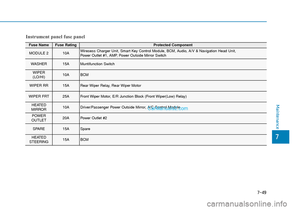
Fuse NameFuse RatingProtected Component
MODULE 57.5AElectro Chromic Mirror, Audio, A/V & Navigation Head Unit, Crash Pad Switch, Head Lamp LH,
Front Air Ventilation Seat Module, Front Seat Warmer Module
MODULE 37.5AStop Lamp Switch, BCM
SUNROOF20ASunroof Unit
TAIL GATEOPEN10ATail Gate Relay
P/WINDOW LH25APower Window LH Relay, Driver Safety Power Window Module
MULTI MEDIA15AAudio, A/V & Navigation Head Unit
P/WINDOWRH25APower Window RH Relay, Passenger Safety Power Window Module
P/SEAT(DRV)25ADriver Seat Manual Switch, Driver Lumbar Support Switch
P/SEAT(PASS)25APassenger Seat Manual Switch
MODULE 47.5ABlind-Spot Collision Warning Unit LH/RH, BCM, Crash Pad Switch, Vess Unit (Speaker),
Multifunction Front View Camera
PDM 37.5ASmart Key Control Module
SPARE20ASpare
Instrument panel fuse panel
Page 429 of 540

7-49
7
Maintenance
Fuse NameFuse RatingProtected Component
MODULE 210AWiresess Charger Unit, Smart Key Control Module, BCM, Audio, A/V & Navigation Head Unit,
Power Outlet #1, AMP, Power Outside Mirror Switch
WASHER15AMuntifunction Switch
WIPER
(LO/HI)10ABCM
WIPER RR15ARear Wiper Relay, Rear Wiper Motor
WIPER FRT25AFront Wiper Motor, E/R Junction Block (Front Wiper(Low) Relay)
HEATED
MIRROR10ADriver/Passenger Power Outside Mirror, A/C Control Module
POWER
OUTLET20APower Outlet #2
SPARE15ASpare
HEATED
STEERING15ABCM
Instrument panel fuse panel
Page 433 of 540

7-53
7
Maintenance
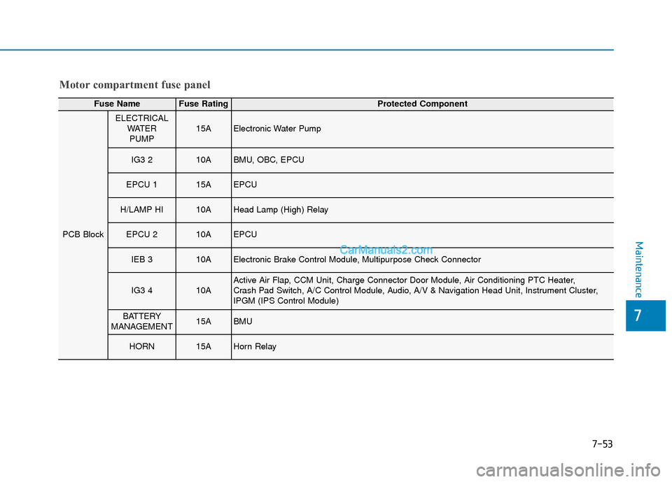
Motor compartment fuse panel
Fuse NameFuse RatingProtected Component
PCB Block
ELECTRICALWATERPUMP15AElectronic Water Pump
IG3 210ABMU, OBC, EPCU
EPCU 115AEPCU
H/LAMP HI10AHead Lamp (High) Relay
EPCU 210AEPCU
IEB 310AElectronic Brake Control Module, Multipurpose Check Connector
IG3 410AActive Air Flap, CCM Unit, Charge Connector Door Module, Air Conditioning PTC Heater,
Crash Pad Switch, A/C Control Module, Audio, A/V & Navigation Head Unit, Instrument Cluster,
IPGM (IPS Control Module)
BATTERY
MANAGEMENT15ABMU
HORN15AHorn Relay
Page 465 of 540

How to Disconnect Portable Charger .........................H41
Charging Connector Manual Release ..........................H42
Precautions When Using the Portable Charger ........H42
EV Charging Troubleshooting
- Steps to Consider ...............................................H43
How to Start the Vehicle ......................................H44
How to Stop the Vehicle.......................................H44
Virtual Engine Sound System ..............................H45
Distance to Empty .................................................H45
When destination is not set ...........................................H46
Navigation - When a Destination is Set .....................H46
Tips for Improving Range When Using the
Climate Control System ........................................H46
Tips for Improving Range While Driving ............H47
Power/Charge Gauge............................................H47
State of Charge (SOC) Gauge for
High Voltage Battery ...........................................H47
Warning and Indicator Lights .............................H48
Ready Indicator ................................................................H48
Service Warning Light .....................................................H48
Power Down Warning Light ...........................................H49
Charging Indicator Light..................................................H49
High Voltage Battery Level Warning Light .................H49
Regenerative Brake Warning Light ..............................H49
LCD Display Messages ..........................................H50
Shift to P to charge .........................................................H50
Remaining Time .................................................................H50
Unplug vehicle to start ....................................................H50
Charging Door Open ........................................................H51Charging Stopped. Check the AC/DC charger ...........H51
Charging Stopped. Check the cable connection .......H52
Check regenerative brakes/
Stop vehicle and check regenerative brakes ............H52 Low Battery........................................................................\
H52
Charge immediately. Power limited ..............................H53
Low outside temperature may limit power output.
Charge EV battery/Low EV battery temperature.
Power limited .....................................................................H53\
EV Battery Overheated! Stop vehicle..........................H54
Power limited .....................................................................H54\
Stop vehicle and check power supply .........................H55
Check Virtual Engine Sound System............................H55
Check electric vehicle system .......................................H55
Energy Flow ..........................................................H56
Vehicle Stop........................................................................\
H56
EV Propulsion ....................................................................H56
Regeneration ......................................................................H5\
6
Aux. Battery Saver+ .............................................H57
Mode ........................................................................\
............H57
System Setting...................................................................H58
LCD Message .....................................................................H58\
Utility Mode ............................................................H59
System Setting and Activation ......................................H59
System Deactivation .........................................................H59
If an Accident Occurs ...........................................H60
Additional Precautions..........................................H62
Service Interlock Connector ................................H62
Service Plug ...........................................................H62
Page 476 of 540

H13
This is primarily due to reduced per-
formance of the EV battery when
exposed to cold temperatures.
Some vehicles may come equipped
with Winter mode selectable option.
The Winter mode feature can be
selected in the EV Settings menu.
When selected, Winter mode
enables the use of the EV battery
coolant heater. This mode is recom-
mended to improve EV battery per-
formance in cold climate conditions.
Note that EV range may reduce
when Winter mode is enabled, as
electrical energy is used to maintain
the EV battery temperature.
Winter mode enables operation of
the EV battery coolant heater. While
driving your vehicle, if the battery
temperature is low or the A/C and/or
heater is turned ON, the EV battery
coolant heater will be used.
Note that the EV battery coolant
heater will not be used when the EV
battery SOC is low.
❈This mode is available for the vehi-
cles equipped with the battery
heater.Warning
You can select or deselect the Range
Warning.
- Range Warning : If the destination
set in the navigation cannot be
reached with the remaining EV bat-
tery charge level, a warning mes-
sage is displayed.
EV route
If EV route is selected, EV related
information will show on the route. You
can check the distance the vehicle
can be driven with the current EV bat-
tery charge level % along the route.
An icon is also indicated so the driver
is able to search for nearby charging
stations.
Page 482 of 540

H19
Scheduled Charging
You can set-up a charging sched-ule for your vehicle using the Audio
or Navigation screen or BlueLink
application.
Refer to the Multimedia manual or
the BlueLink manual for detailed
information about setting sched-
uled charging.
Scheduled charging can only be done when using a Level 2 AC
charging station or the Level 1 AC
charger with the Hyundai-supplied
charging power cord. When scheduled charging has
been set and the charging cable is
connected, the indicator lamp
blinks green (1) for 3 minutes, indi-
cating that scheduled charging is
enabled.
If immediate charging is required, use the audio/infotainment screen
menus to deactivate the scheduled
charge setting, or press the sched-
uled charging deactivation button
(2) for 3 seconds.
OOSEVQ018070N
S
SC
C H
H E
ED
D U
U L
LE
E D
D
C
C H
H A
AR
RG
G I
IN
N G
G
Page 509 of 540

H46
D
DR
RI
IV
V I
IN
N G
G
A
A N
N D
D
O
O P
PE
ER
R A
A T
TI
IN
N G
G
I
IN
N F
FO
O R
RM
M A
AT
TI
IO
O N
N
(
( C
C O
O N
NT
T.
.)
)
When destination is not set
On average, a vehicle can drive
about 250 miles (400 km). Under
certain circumstances where the
air conditioner/heater is ON, the
range is affected, resulting in a
possible distance range from
210~310 miles (335~500 km).
When using the heater during cold
weather or driving at high speed,
the high voltage battery consumes
a lot more electricity. This may
reduce the range significantly.
After "---" has been displayed, the vehicle can drive an additional 2~5
miles (3~8 km) depending on driv-
ing speed, heater/air conditioner,
weather, driving style, and other
factors.
The range that is displayed on the instrument cluster after completing
a recharge may vary significantly
depending on previous driving pat-
terns.
When the previous driving patterns
include aggressive or high speed
driving (e.g. predominantly high-
way miles, etc.), the estimated
range on the next full charge will be
lower than normal. When the previous driving patterns
are predominantly mild or econom-
ical (e.g. city driving), the estimated
range on the next full charge will be
increased.
Calculated range may depend on many factors such as the charge
amount of the high voltage battery,
weather, temperature, durability of
the battery, geographical features,
and driving style.
Natural degradation may occur with the high voltage battery
depending on the number of years
the vehicle is used. This may
reduce the vehicle range.
Navigation - When a Destinationis Set
When a destination is set using the
vehicle navigation system (if
equipped), the vehicle range may
change. The vehicle range is recalcu-
lated using the destination route infor-
mation. While driving, the range may
vary based on traffic conditions, driv-
ing pattern and vehicle settings, etc.
Tips for Improving Range
When Using the Climate
Control System
Operating the climate control sys-
tem consumes electrical energy
from the EV battery. Continuous use
may reduce the vehicle range.
When using the climate control sys-
tem, it is recommended to set the
control to 72°F (22°C) AUTO. The
climate control system has been
optimized to operate at this setting
for maximum comfort and efficiency.
When possible, use the DRIVER ONLY feature on the climate control
system. This will discontinue airflow
to the passenger side and reduces
climate control power consumption.