Page 49 of 599
H49
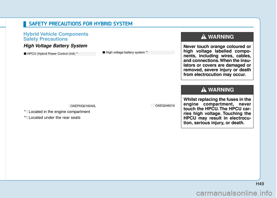
Hybrid Vehicle Components
Safety Precautions
High Voltage Battery SystemNever touch orange coloured or
high voltage labelled compo-
nents, including wires, cables,
and connections. When the insu-
lators or covers are damaged or
removed, severe injury or death
from electrocution may occur.
WARNING
Whilst replacing the fuses in the
engine compartment, never
touch the HPCU. The HPCU car-
ries high voltage. Touching the
HPCU may result in electrocu-
tion, serious injury, or death.
WARNING
S SA
A F
FE
E T
T Y
Y
P
P R
R E
EC
CA
A U
U T
TI
IO
O N
NS
S
F
F O
O R
R
H
H Y
Y B
BR
RI
ID
D
S
S Y
Y S
ST
T E
EM
M
OAEQ046019
■ High voltage battery system *2
*1: Located in the engine compartment
*
2: Located under the rear seats
OAEPHQ016040L
■ HPCU (Hybrid Power Control Unit) *1
Page 52 of 599
H52
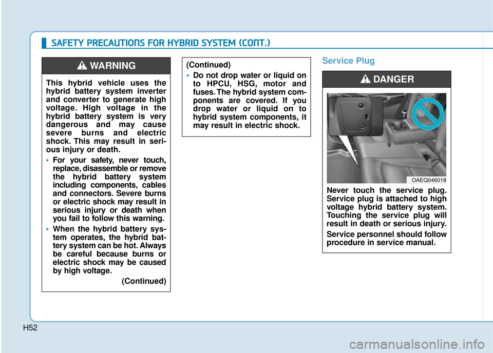
Service Plug
Never touch the service plug.
Service plug is attached to high
voltage hybrid battery system.
Touching the service plug will
result in death or serious injury.
Service personnel should follow
procedure in service manual.
DANGER
OAEQ046018
S
SA
A F
FE
E T
T Y
Y
P
P R
R E
EC
CA
A U
U T
TI
IO
O N
NS
S
F
F O
O R
R
H
H Y
Y B
BR
RI
ID
D
S
S Y
Y S
ST
T E
EM
M
(
( C
C O
O N
NT
T.
.)
)
(Continued)
Do not drop water or liquid on
to HPCU, HSG, motor and
fuses. The hybrid system com-
ponents are covered. If you
drop water or liquid on to
hybrid system compone nts, it
may result in electric shock.
This hybrid vehicle uses the
hybrid battery system inverter
and converter to generate high
voltage. High voltage in the
hybrid battery system is very
dangerous and may cause
severe burns and electric
shock. This may result in seri-
ous injury or death.
For your safety, never touch,
replace, disassemble or remove
the hybrid battery system
including components, cables
and connectors. Severe burns
or electric shock may result in
serious injury or death when
you fail to follow this warning.
When the hybrid battery sys-
tem operates, the hybrid bat-
tery system can be hot. Always
be careful because burns or
electric shock may be caused
by high voltage.
(Continued)
WARNING
Page 70 of 599

1-4
Your vehicle at a glance
I
IN
N T
TE
ER
R I
IO
O R
R
O
O V
VE
ER
R V
V I
IE
E W
W
-
-
H
H Y
Y B
BR
RI
ID
D
V
V E
EH
H I
IC
C L
LE
E
1. Door lock/unlock button ....................3-14
2. Driver position memory system ........3-18
3. Outside rearview mirror folding
switch ................................................3-26
4. Outside rearview mirror control switch ................................................3-25
5. Central door lock switch ....................3-14
6. Power window switches ....................3-27
7. Power window lock switch ................3-30
8. Headlamp levelling device ..............3-112
9. Instrument panel illumination control switch ......................................3-46
10. Blind-Spot Collision Warning (BCW) system................................................5-41
11. Lane keeping assist (LKA) system....5-63
12. ESC OFF button ..............................5-33
13. Fuel filler door opener ....................3-38
14. 12V battery reset switch ....................6-5
15. Bonnet release lever........................3-35
16. Fuse box ..........................................7-41
17. Steering wheel ................................3-20
18. Seat ..................................................2-4
OAEPH017008LThe actual shape may differ from the illustration.
Page 72 of 599
1-6
Your vehicle at a glance
E
EN
N G
GI
IN
N E
E
C
C O
O M
M P
PA
A R
RT
TM
M E
EN
N T
T
-
-
H
H Y
Y B
BR
RI
ID
D
V
V E
EH
H I
IC
C L
LE
E
OAE076001
■
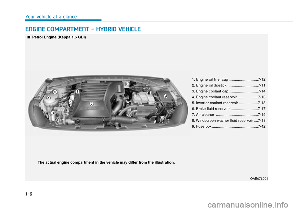
■Petrol Engine (Kappa 1.6 GDI)
1. Engine oil filler cap ............................7-12
2. Engine oil dipstick ............................7-11
3. Engine coolant cap ............................7-14
4. Engine coolant reservoir ..................7-13
5. Inverter coolant reservoir ..................7-13
6. Brake fluid reservoir ..........................7-17
7. Air cleaner ........................................7-19
8. Windscreen washer fluid reservoir ....7-18
9. Fuse box ............................................7-42
The actual engine compartment in the vehicle may differ from the illustration.
Page 75 of 599
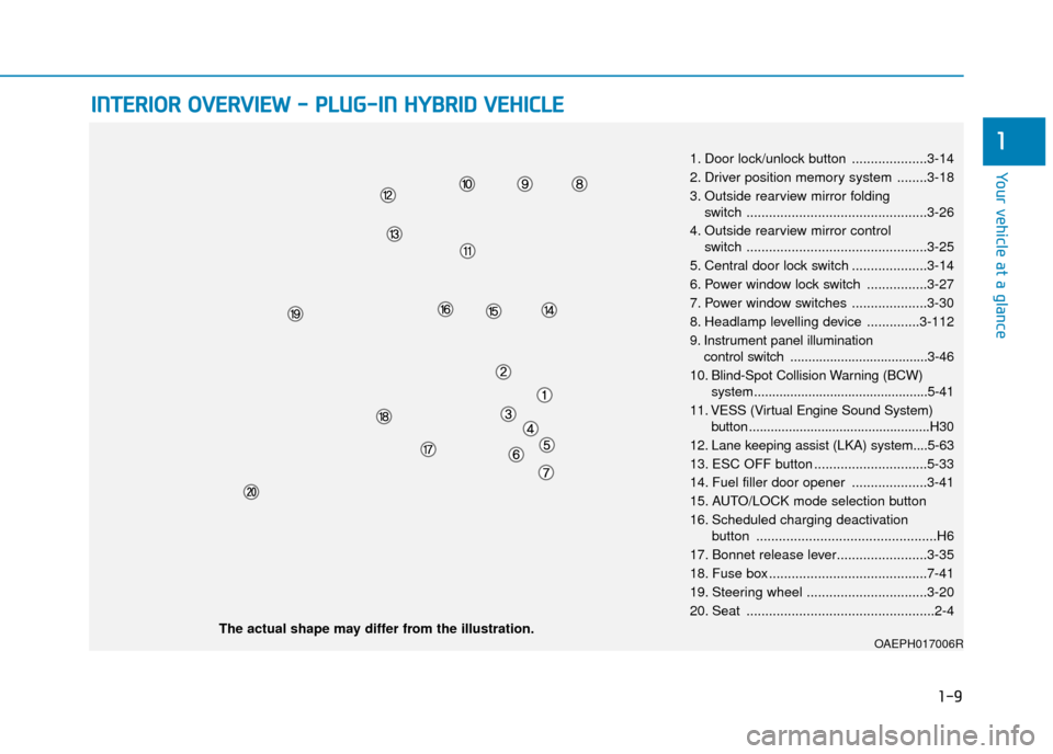
1-9
Your vehicle at a glance
1
I
IN
N T
TE
ER
R I
IO
O R
R
O
O V
VE
ER
R V
V I
IE
E W
W
-
-
P
P L
LU
U G
G-
-I
IN
N
H
H Y
Y B
BR
RI
ID
D
V
V E
EH
H I
IC
C L
LE
E
1. Door lock/unlock button ....................3-14
2. Driver position memory system ........3-18
3. Outside rearview mirror folding
switch ................................................3-26
4. Outside rearview mirror control switch ................................................3-25
5. Central door lock switch ....................3-14
6. Power window lock switch ................3-27
7. Power window switches ....................3-30
8. Headlamp levelling device ..............3-112
9. Instrument panel illumination control switch ......................................3-46
10. Blind-Spot Collision Warning (BCW) system................................................5-41
11. VESS (Virtual Engine Sound System) button ..................................................H30
12. Lane keeping assist (LKA) system....5-63
13. ESC OFF button ..............................5-33
14. Fuel filler door opener ....................3-41
15. AUTO/LOCK mode selection button
16. Scheduled charging deactivation button ................................................H6
17. Bonnet release lever........................3-35
18. Fuse box ..........................................7-41
19. Steering wheel ................................3-20
20. Seat ..................................................2-4
OAEPH017006RThe actual shape may differ from the illustration.
Page 77 of 599
1-11
Your vehicle at a glance
1
E
EN
N G
GI
IN
N E
E
C
C O
O M
M P
PA
A R
RT
TM
M E
EN
N T
T
-
-
P
P L
LU
U G
G-
-I
IN
N
H
H Y
Y B
BR
RI
ID
D
V
V E
EH
H I
IC
C L
LE
E
OAEPH076001
■
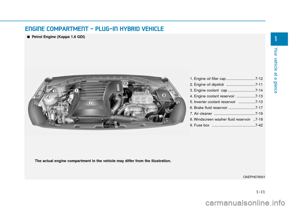
■Petrol Engine (Kappa 1.6 GDI)
1. Engine oil filler cap ............................7-12
2. Engine oil dipstick ............................7-11
3. Engine coolant cap ..........................7-14
4. Engine coolant reservoir ..................7-13
5. Inverter coolant reservoir ................7-13
6. Brake fluid reservoir ..........................7-17
7. Air cleaner ........................................7-19
8. Windscreen washer fluid reservoir ..7-18
9. Fuse box ..........................................7-42
The actual engine compartment in the vehicle may differ from the illustration.
Page 176 of 599

3-30
Convenient features of your vehicle
Information
The automatic reverse feature is only
active when the “Auto Up” feature is
used by fully pulling up the switch to
the second detent.
Do not install any accessories on
the windows. The automatic
reverse feature may not operate.
Power window lock switch
The driver can disable the power
window switches on the rear passen-
gers' doors by pressing the power
window lock switch.
When the power window lock switch
is pressed:
The driver's master control canoperate all the power windows.
The front passenger's control can operate the front passenger's power
window.
The rear passenger's control can- not operate the rear passengers'
power window. To prevent possible damage to
the power window system, do
not open or close two windows
or more at the same time. This
will also ensure the longevity of
the fuse.
Never try to operate the main switch on the driver's door and
the individual door window
switch in opposite directions at
the same time. If this is done, the
window will stop and cannot be
opened or closed.
NOTICE
NOTICE
i
Make sure body parts or other
objects are safely out of the way
before closing the windows to
avoid injuries or vehicle damage.
Objects less than 4 mm (0.16
inch) in diameter caught between
the window glass and the upper
window channel may not be
detected by the automatic reverse
window and the window will not
stop and reverse direction.
WARNING
Do not allow children to play
with the power windows. Keep
the driver’s door power window
lock switch in the LOCK posi-
tion. Serious injury or death can
result from unintentional win-
dow operation by a child.
WARNING
OAE046021R
Page 180 of 599

3-34
Convenient features of your vehicle
Periodically remove any dirt that may accumulate on the sunroof
guide rail or between the sun-
roof and roof panel, which can
make a noise.
Do not try to open the sunroof when the temperature is below
freezing or when the sunroof is
covered with snow or ice, other-
wise the motor could be dam-
aged. In cold and wet climates, the
sunroof may not work properly.
Sunshade
The sunshade will open automatical-
ly with the sunroof when the glass
panel moves. If you want it closed,
move the sunshade manually.
The sunroof is made to slide
together with the sunshade. Do
not leave the sunshade closed
whilst the sunroof is open.
Resetting the sunroof
The sunroof may need to be reset if
the following conditions occur:
- The battery is discharged or dis-connected or the sunroof fuse has
been replaced or disconnected
- The sunroof control lever is not operating correctly
To reset the sunroof, perform the fol-
lowing steps:
1. Place the ignition switch to the ON position or start the engine. It is rec-
ommended to reset the sunroof
whilst the engine is running.
2. Push the control lever forward. The sunroof will close completely or tilt
depending on the condition of the
sunroof.
3. Release the control lever until the sunroof does not move.
NOTICE
NOTICE
OAD045037