2019 Hyundai Ioniq Hybrid Parking brake
[x] Cancel search: Parking brakePage 458 of 603
7-13
7
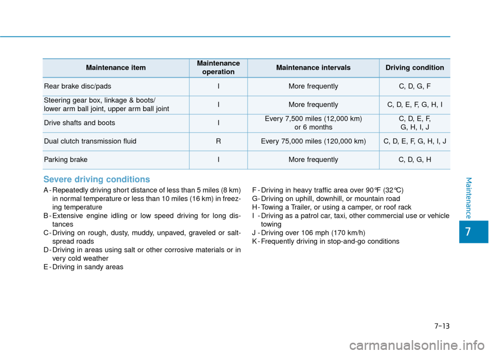
MaintenanceSevere driving conditions
A - Repeatedly driving short distance of less than 5 miles (8 km)in normal temperature or less than 10 miles (16 km) in freez-
ing temperature
B - Extensive engine idling or low speed driving for long dis- tances
C - Driving on rough, dusty, muddy, unpaved, graveled or salt- spread roads
D - Driving in areas using salt or other corrosive materials or in very cold weather
E - Driving in sandy areas F - Driving in heavy traffic area over 90°F (32°C)
G- Driving on uphill, downhill, or mountain road
H - Towing a Trailer, or using a camper, or roof rack
I - Driving as a patrol car, taxi, other commercial use or vehicle
towing
J - Driving over 106 mph (170 km/h)
K - Frequently driving in stop-and-go conditions
Maintenance itemMaintenance operationMaintenance intervalsDriving condition
Rear brake disc/padsIMore frequentlyC, D, G, F
Steering gear box, linkage & boots/
lower arm ball joint, upper arm ball jointIMore frequentlyC, D, E, F, G, H, I
Drive shafts and bootsIEvery 7,500 miles (12,000 km) or 6 monthsC, D, E, F, G, H, I, J
Dual clutch transmission fluidREvery 75,000 miles (120,000 km)C, D, E, F, G, H, I, J
Parking brakeIMore frequentlyC, D, G, H
Page 460 of 603
7-15
7
Maintenance
Dual Clutch Transmission
Fluid
The dual clutch transmission fluid
should be inspected according to the
intervals specified in the mainte-
nance schedule.
Engine Clutch Actuator Fluid
The engine clutch actuator fluid level
should be inspected or replaced to
the intervals specified in the mainte-
nance schedule.
Brake Hoses and Lines
Visually check for proper installation,
chafing, cracks, deterioration and
any leakage. Replace any deteriorat-
ed or damaged parts immediately.
Brake Fluid
Check the brake fluid level in the
brake the fluid reservoir. The level
should be between the MIN and the
MAX marks on the side of the reser-
voir. Use only hydraulic brake fluid
conforming to DOT 3 or DOT 4 spec-
ification.
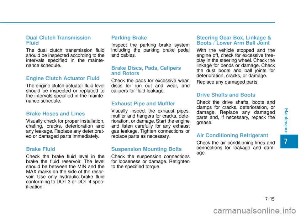
Parking Brake
Inspect the parking brake system
including the parking brake pedal
and cables.
Brake Discs, Pads, Calipers
and Rotors
Check the pads for excessive wear,
discs for run out and wear, and
calipers for fluid leakage.
Exhaust Pipe and Muffler
Visually inspect the exhaust pipes,
muffler and hangers for cracks, dete-
rioration, or damage. Start the engine
and listen carefully for any exhaust
gas leakage. Tighten connections or
replace parts as necessary.
Suspension Mounting Bolts
Check the suspension connections
for looseness or damage. Retighten
to the specified torque.
Steering Gear Box, Linkage &
Boots / Lower Arm Ball Joint
With the vehicle stopped and the
engine off, check for excessive free-
play in the steering wheel. Check the
linkage for bends or damage. Check
the dust boots and ball joints for
deterioration, cracks, or damage.
Replace any damaged parts.
Drive Shafts and Boots
Check the drive shafts, boots and
clamps for cracks, deterioration, or
damage. Replace any damaged
parts and, if necessary, repack the
grease.
Air Conditioning Refrigerant
Check the air conditioning lines and
connections for leakage and dam-
age.
Page 469 of 603
7-24
Maintenance
P
PA
A R
RK
K I
IN
N G
G
B
B R
RA
A K
KE
E
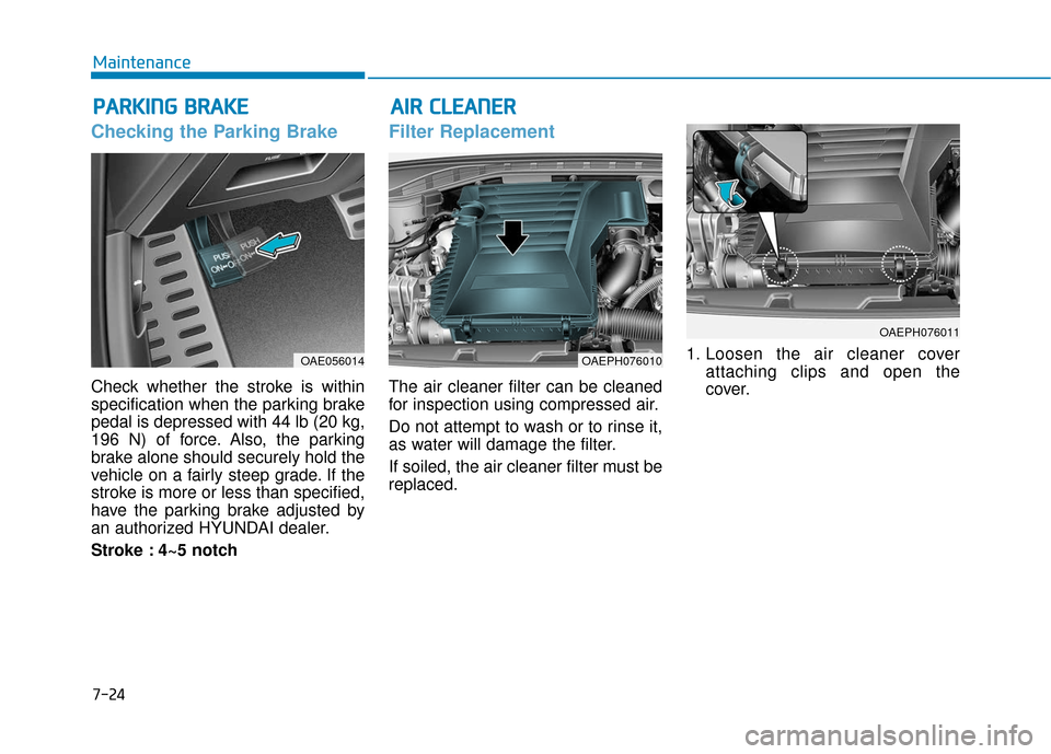
Checking the Parking Brake
Check whether the stroke is within
specification when the parking brake
pedal is depressed with 44 lb (20 kg,
196 N) of force. Also, the parking
brake alone should securely hold the
vehicle on a fairly steep grade. If the
stroke is more or less than specified,
have the parking brake adjusted by
an authorized HYUNDAI dealer.
Stroke : 4~5 notch
Filter Replacement
The air cleaner filter can be cleaned
for inspection using compressed air.
Do not attempt to wash or to rinse it,
as water will damage the filter.
If soiled, the air cleaner filter must be
replaced. 1. Loosen the air cleaner cover
attaching clips and open the
cover.
OAE056014
A
AI
IR
R
C
C L
LE
E A
A N
N E
ER
R
OAEPH076010
OAEPH076011
Page 500 of 603
7-55
7
Maintenance
L
LI
IG
G H
H T
T
B
B U
U L
LB
B S
S
Consult an authorized HYUNDAI
dealer to replace most vehicle light
bulbs. It is difficult to replace vehicle
light bulbs because other parts of the
vehicle must be removed before you
can get to the bulb. This is especially
true for removing the headlamp
assembly to get to the bulb(s).
Removing/installing the headlamp
assembly can result in damage to
the vehicle.
Information
After heavy driving rain or washing,
lamps could appear frosty. This condi-
tion is caused by the temperature dif-
ference between the lamp inside and
the outside temperature. This is simi-
lar to the condensation on your win-
dows inside your vehicle when raining
and doesn 't indicate a problem with
your vehicle. If the water leaks into
the lamp bulb circuitry, have your
vehicle checked by an authorized
HYUNDAI dealer.
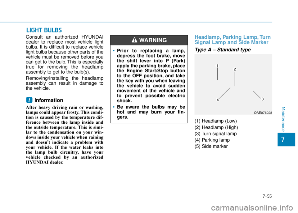
Headlamp, Parking Lamp, Turn
Signal Lamp and Side Marker
Type A – Standard type
(1) Headlamp (Low)
(2) Headlamp (High)
(3) Turn signal lamp
(4) Parking lamp
(5) Side marker
i
Prior to replacing a lamp,
depress the foot brake, move
the shift lever into P (Park)
apply the parking brake, place
the Engine Start/Stop button
to the OFF position, and take
the key with you when leaving
the vehicle to avoid sudden
movement of the vehicle and
to prevent possible electric
shock.
Be aware the bulbs may be
hot and may burn your fin-
gers.
WARNING
OAE076028
Page 545 of 603
H10
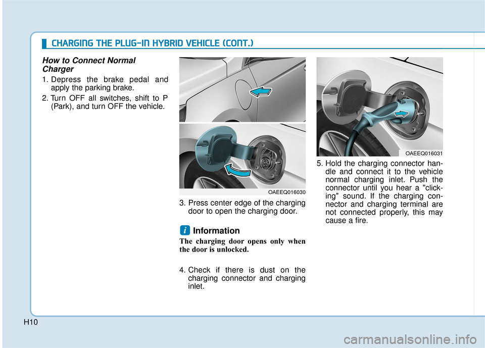
How to Connect NormalCharger
1. Depress the brake pedal and
apply the parking brake.
2. Turn OFF all switches, shift to P (Park), and turn OFF the vehicle.
3. Press center edge of the chargingdoor to open the charging door.
Information
The charging door opens only when
the door is unlocked.
4. Check if there is dust on thecharging connector and charging
inlet. 5. Hold the charging connector han-
dle and connect it to the vehicle
normal charging inlet. Push the
connector until you hear a "click-
ing" sound. If the charging con-
nector and charging terminal are
not connected properly, this may
cause a fire.
i
OAEEQ016030
OAEEQ016031
C
CH
H A
AR
RG
G I
IN
N G
G
T
T H
H E
E
P
P L
LU
U G
G-
-I
IN
N
H
H Y
Y B
BR
RI
ID
D
V
V E
EH
H I
IC
C L
LE
E
(
( C
C O
O N
NT
T.
.)
)
Page 553 of 603
H18
C
CH
H A
AR
RG
G I
IN
N G
G
T
T H
H E
E
P
P L
LU
U G
G-
-I
IN
N
H
H Y
Y B
BR
RI
ID
D
V
V E
EH
H I
IC
C L
LE
E
(
( C
C O
O N
NT
T.
.)
)
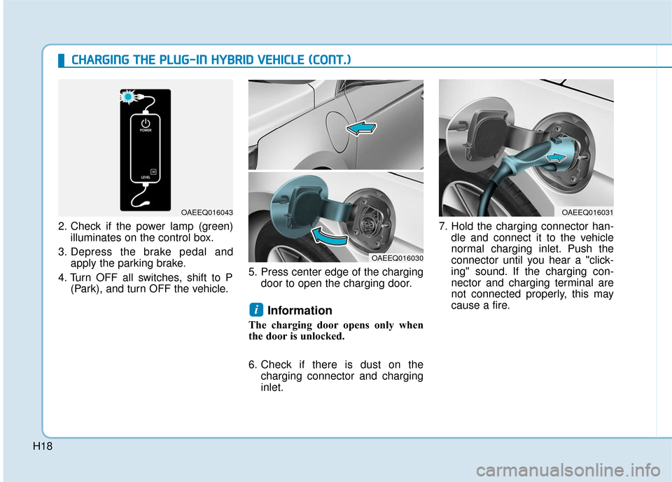
2. Check if the power lamp (green)
illuminates on the control box.
3. Depress the brake pedal and apply the parking brake.
4. Turn OFF all switches, shift to P (Park), and turn OFF the vehicle. 5. Press center edge of the charging
door to open the charging door.
Information
The charging door opens only when
the door is unlocked.
6. Check if there is dust on thecharging connector and charging
inlet. 7. Hold the charging connector han-
dle and connect it to the vehicle
normal charging inlet. Push the
connector until you hear a "click-
ing" sound. If the charging con-
nector and charging terminal are
not connected properly, this may
cause a fire.
i
OAEEQ016030
OAEEQ016031OAEEQ016043
Page 562 of 603
H27
Starting the Vehicle
1. Carry the smart key or leave itinside the vehicle.
2. Make sure the parking brake is firmly applied.
3. Place the shift lever in P (Park). With the shift lever in N (Neutral),
you cannot start the vehicle.
4. Depress the brake pedal.
5. Press the Engine Start/Stop but- ton. If the hybrid system starts, the
" " indicator will come on.
Whether the engine is cold or warm, it should be started without
depressing the accelerator.
After following the start proce-
dures, " " indicator on the
instrument cluster will turn on.
For more information, please
check Chapter 5. ECONOMICAL and SAFE OPERA-
TION of Hybrid system
Drive smoothly. Accelerate at a
moderate rate and maintain a
steady cruising speed. Do not
make "jack-rabbit" starts. Do not
race between stoplights.
Avoid heavy traffic whenever pos-
sible. Always maintain a safe dis-
tance from other vehicles so you
can avoid unnecessary braking.
This also reduces brake wear.
The regenerative brake generates energy when the vehicle deceler-
ates.
When the hybrid battery power is low, the hybrid system automatical-
ly recharges the hybrid battery.
When the engine is running with the shift lever in N (Neutral), the
hybrid system cannot generate
electricity. The hybrid battery can-
not recharge with the shift lever in N
(Neutral).
Information
In the hybrid system, the engine auto-
matically runs and stops. When the
hybrid system operates, the " "
indicator is illuminated.
In the following situation, the engine
may operate automatically.
- When the engine is ready to run
- When the hybrid battery is beingcharged
- Depending on the temperature con- dition of the hybrid battery
i
D
DR
RI
IV
V I
IN
N G
G
T
T H
H E
E
H
H Y
Y B
BR
RI
ID
D /
/P
P L
LU
U G
G-
-I
IN
N
H
H Y
Y B
BR
RI
ID
D
V
V E
EH
H I
IC
C L
LE
E
Page 591 of 603
I-3
Automatic ventilation ...................................................3-149
AUX, USB and iPod®Port ...............................................4-2
Batterty (12 volt, Plug-in hybrid vehicle).......................7-31
Battery cooling duct........................................................2-22
Battery saver function ...................................................3-122
Before driving ...................................................................5-4
Blind-spot Collision Warning (BCW) system ................5-34
Blind spot mirror.............................................................3-34
Blue Link
®center ...........................................................3-19
Bluetooth®Wireless Technology hands-free ....................4-4
Bottle holder .................................................................3-152
Brake fluid ......................................................................7-\
22
Brake system ...................................................................5-23 Anti-lock Brake System (ABS)..................................5-26
Disc brakes wear indicator .........................................5-24
Electronic Stability Control (ESC).............................5-28
Good braking practices ..............................................5-33
Hill-start Assist Control (HAC) .................................5-33
Parking brake..............................................................5-24
Power brakes ..............................................................5-23
Vehicle Stability Management (VSM) .......................5-31 Bulb replacement ............................................................7-55
Daytime Running Lamp (DRL) .................................7-60
Front parking lamp .....................................................7-55
Front turn signal lamp ................................................7-55
Headlamp....................................................................7-55\
High mounted stop lamp ............................................7-64
Interior light bulb .......................................................7-65
License plate light bulb ..............................................7-65
Rear combination light bulb .......................................7-61
Side marker ................................................................7-55
Side repeater lamp ......................................................7-61
Bulb wattage .....................................................................8-3\
Button start/stop, see engine start/stop button ..................5-6
Capacities (Lubricants) .....................................................8-7
Care Exterior care ...............................................................7-67
Interior care ................................................................7-71
Tire care ......................................................................7-\
34
Cargo security screen ....................................................3-159
Center console storage ..................................................3-150
Central door lock switch .................................................3-11
Certification label location ...............................................8-9
Chains Tire chains ..................................................................5-96
Checking tire inflation pressure ......................................7-36
I
Index
B
C