2019 Hyundai Ioniq Electric power steering
[x] Cancel search: power steeringPage 296 of 555
5-29
Driving your vehicle
5
When you drive on a road having
poor traction, such as an icy road,
and apply your brakes continu-
ously, the ABS will be active con-
tinuously and the ABS warning
light ( ) may illuminate. Pull
your car over to a safe place and
turn the vehicle off.
Restart the vehicle. If the ABS
warning light is off, then your ABS
system is normal.
Otherwise, you may have a prob-
lem with your ABS system.
Contact an authorized HYUNDAI
dealer as soon as possible.
Information
When you jump start your vehicle
because of a drained battery, the ABS
warning light ( ) may turn on at the
same time. This happens because of
the low battery voltage. It does not
mean your ABS is malfunctioning.
Have the battery recharged before
driving the vehicle.
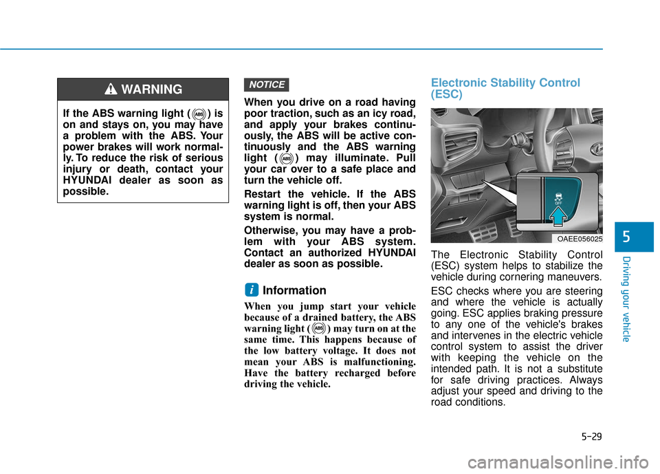
Electronic Stability Control
(ESC)
The Electronic Stability Control
(ESC) system helps to stabilize the
vehicle during cornering maneuvers.
ESC checks where you are steering
and where the vehicle is actually
going. ESC applies braking pressure
to any one of the vehicle's brakes
and intervenes in the electric vehicle
control system to assist the driver
with keeping the vehicle on the
intended path. It is not a substitute
for safe driving practices. Always
adjust your speed and driving to the
road conditions.
i
NOTICE
If the ABS warning light ( ) is
on and stays on, you may have
a problem with the ABS. Your
power brakes will work normal-
ly. To reduce the risk of serious
injury or death, contact your
HYUNDAI dealer as soon as
possible.
WARNING
OAEE056025
Page 300 of 555
5-33
Driving your vehicle
5
Vehicle Stability Management
(VSM)
The Vehicle Stability Management
(VSM) is a function of the Electronic
Stability Control (ESC) system. It
helps ensure the vehicle stays stable
when accelerating or braking sud-
denly on wet, slippery and rough
roads where traction over the four
tires can suddenly become uneven.
VSM operation
VSM ON condition
The VSM operates when:
The Electronic Stability Control(ESC) is on.
Vehicle speed is approximately above 9 mph (15 km/h) on curve
roads.
Vehicle speed is approximately above 12 mph (20 km/h) when the
vehicle is braking on rough roads.
When operating
When you apply your brakes under
conditions which may activate the
ESC, you may hear sounds from the
brakes, or feel a corresponding sen-
sation in the brake pedal. This is nor-
mal and it means your VSM is active.
Information
The VSM does not operate when:
• Driving on a banked road such as agradient or incline.
• Driving in reverse.
• The ESC OFF indicator light is on.
• The EPS (Electric power steering)
warning light ( ) is on or blinks.
i
Take the following precautions
when using the Vehicle Stability
Management (VSM):
ALWAYS check the speed and
the distance to the vehicle
ahead. The VSM is not a substi-
tute for safe driving practices.
Never drive too fast for the
road conditions. The VSM sys-
tem will not prevent acci-
dents. Excessive speed in bad
weather, slippery and uneven
roads can result in severe
accidents.
WARNING
Page 315 of 555
5-48
Driving your vehicle
Prerequisite for activation
The FCA system is on and ready
when FCA is selected on the LCD
display and when the following pre-
requisites are satisfied:
- The ESC (Electronic StabilityControl) is activated.
- Driving speed exceeds approxi- mately 6 mph (10 km/h). (The FCA
is only activated within a certain
speed range.)
- The system detects a pedestrian or a vehicle in front, which may collide
with your vehicle. (The FCA may
not be activated or may sound a
warning alarm in accordance with
the driving situation or vehicle con-
dition.)
FCA Warning Message and
System Control
The FCA produces warning mes-
sages and warning alarms in accor-
dance with the collision risk levels,
such as abrupt stopping of the vehi-
cle in front, insufficient braking dis-
tance, or pedestrian detection. Also,
it controls the brakes in accordance
with the collision risk levels.Completely stop the vehicle
on a safe location before
operating the switch on the
steering wheel to activate/
deactivate the FCA system.
The FCA automatically acti-
vates when the POWER but-
ton is in the ON position. The
driver can deactivate the FCA
by canceling the system set-
ting on the LCD display.
If you cancel the ESC
(Electronic Stability Control)
when the FCA system is
turned on the FCA automati-
cally deactivates and the FCA
warning light illuminates.
When the ESC is cancelled
the FCA cannot be activated
on the LCD display.
WARNING
Page 317 of 555
5-50
Driving your vehicle
Brake operation
In an urgent situation, the brakingsystem enters into the ready status
for prompt reaction against the dri-
ver's depressing the brake pedal.
The FCA provides additional brak- ing power for optimum braking per-
formance, when the driver
depresses the brake pedal.
The braking control is automatical- ly deactivated, when the driver
sharply depresses the accelerator
pedal, or when the driver abruptly
operates the steering wheel.
The FCA brake control is automat- ically canceled, when risk factors
disappear.
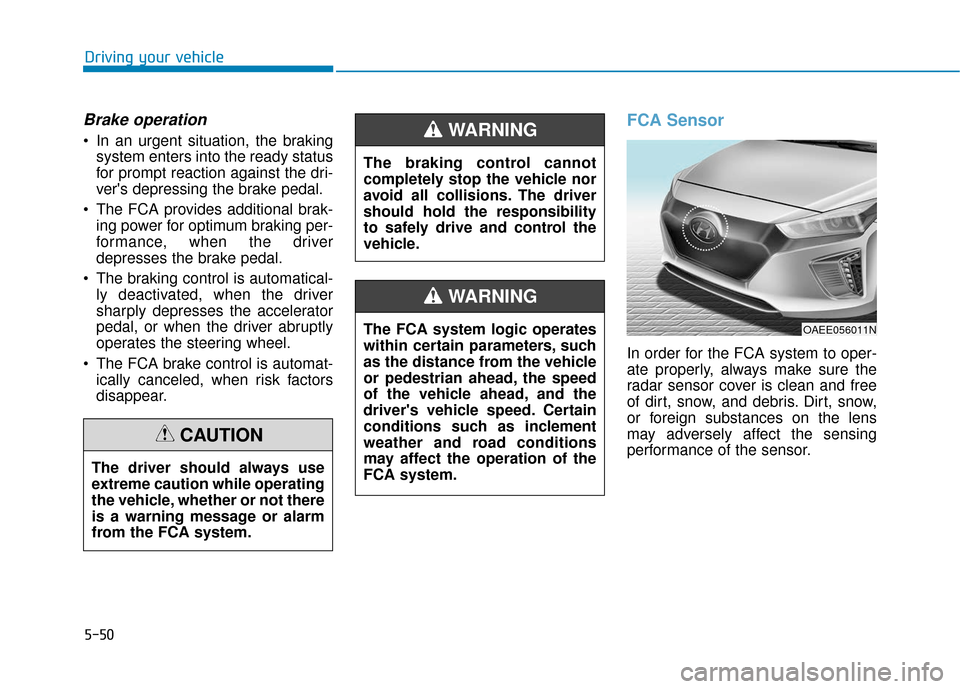
FCA Sensor
In order for the FCA system to oper-
ate properly, always make sure the
radar sensor cover is clean and free
of dirt, snow, and debris. Dirt, snow,
or foreign substances on the lens
may adversely affect the sensing
performance of the sensor.
The driver should always use
extreme caution while operating
the vehicle, whether or not there
is a warning message or alarm
from the FCA system.
CAUTION
The braking control cannot
completely stop the vehicle nor
avoid all collisions. The driver
should hold the responsibility
to safely drive and control the
vehicle.
WARNING
The FCA system logic operates
within certain parameters, such
as the distance from the vehicle
or pedestrian ahead, the speed
of the vehicle ahead, and the
driver's vehicle speed. Certain
conditions such as inclement
weather and road conditions
may affect the operation of the
FCA system.
WARNING
OAEE056011N
Page 328 of 555
5-61
Driving your vehicle
5
LKA System Operation
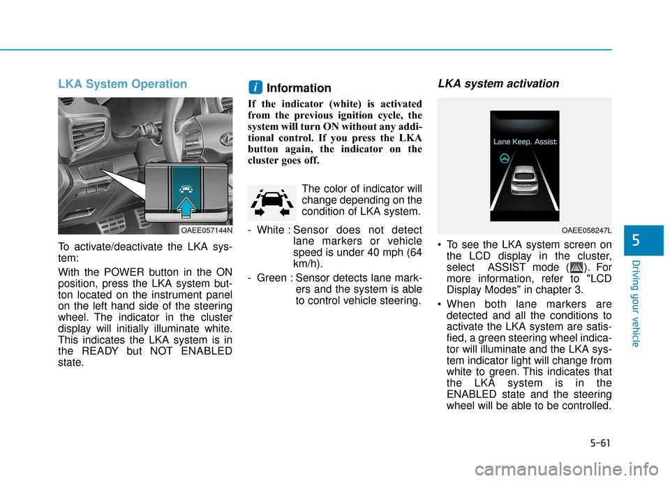
To activate/deactivate the LKA sys-
tem:
With the POWER button in the ON
position, press the LKA system but-
ton located on the instrument panel
on the left hand side of the steering
wheel. The indicator in the cluster
display will initially illuminate white.
This indicates the LKA system is in
the READY but NOT ENABLED
state.
Information
If the indicator (white) is activated
from the previous ignition cycle, the
system will turn ON without any addi-
tional control. If you press the LKA
button again, the indicator on the
cluster goes off. The color of indicator will
change depending on the
condition of LKA system.
- White : Sensor does not detect
lane markers or vehicle
speed is under 40 mph (64
km/h).
- Green : Sensor detects lane mark- ers and the system is able
to control vehicle steering.
LKA system activation
To see the LKA system screen onthe LCD display in the cluster,
select ASSIST mode ( ). For
more information, refer to "LCD
Display Modes" in chapter 3.
When both lane markers are detected and all the conditions to
activate the LKA system are satis-
fied, a green steering wheel indica-
tor will illuminate and the LKA sys-
tem indicator light will change from
white to green. This indicates that
the LKA system is in the
ENABLED state and the steering
wheel will be able to be controlled.
i
OAEE057144NOAEE058247L
Page 341 of 555
5-74
Driving your vehicle
Information
• During normal cruise control opera-tion, when the SET switch is activat-
ed or reactivated after applying the
brakes, the cruise control will ener-
gize after approximately 3 seconds.
This delay is normal.
• Before activating the cruise control function, the system will check to
verify that the brake switch is oper-
ating normally. Depress the brake
pedal at least once after turning ON
the POWER button or starting the
vehicle.
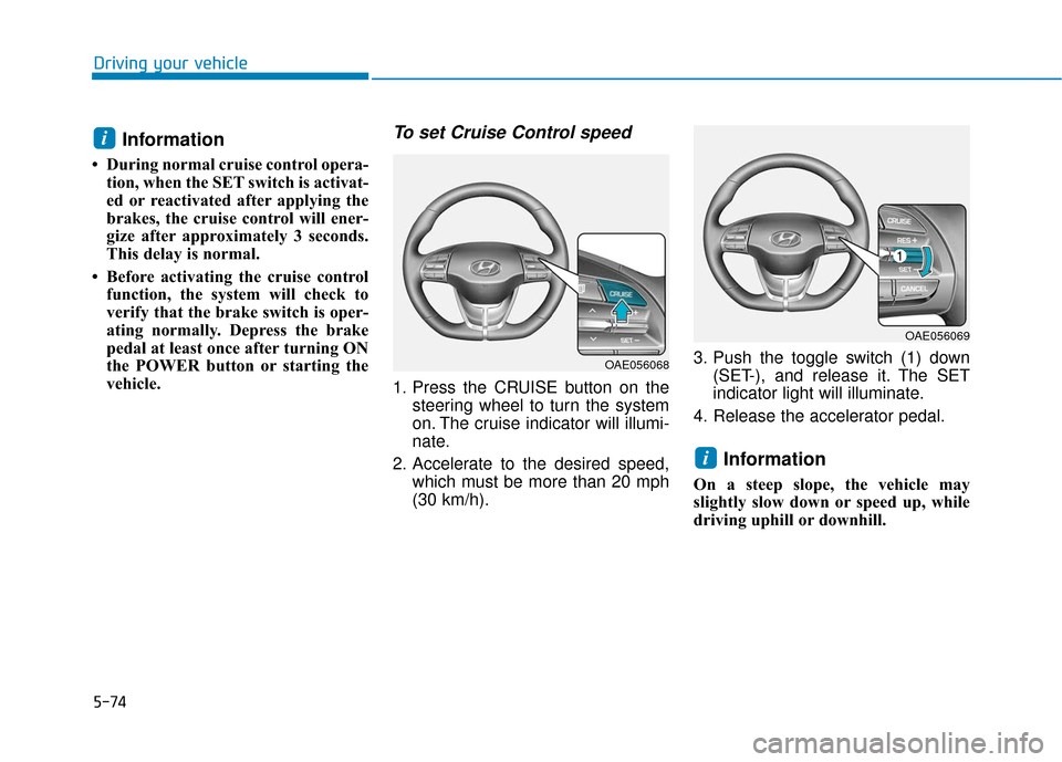
To set Cruise Control speed
1. Press the CRUISE button on the steering wheel to turn the system
on. The cruise indicator will illumi-
nate.
2. Accelerate to the desired speed, which must be more than 20 mph
(30 km/h). 3. Push the toggle switch (1) down
(SET-), and release it. The SET
indicator light will illuminate.
4. Release the accelerator pedal.
Information
On a steep slope, the vehicle may
slightly slow down or speed up, while
driving uphill or downhill.
i
i
OAE056068
OAE056069
Page 396 of 555
6-23
What to do in an emergency
6
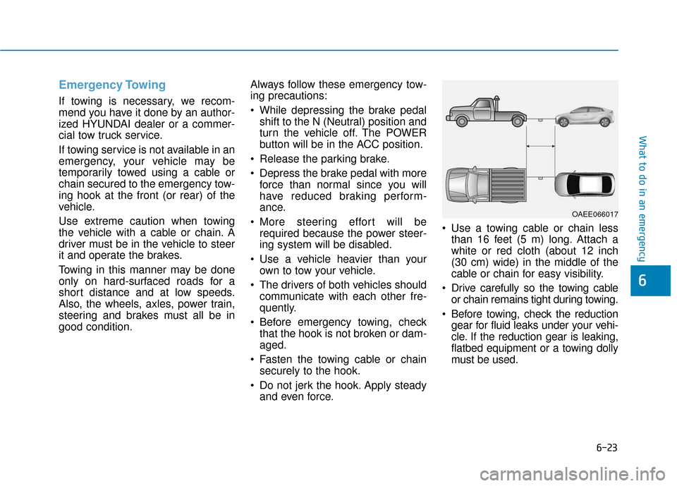
Emergency Towing
If towing is necessary, we recom-
mend you have it done by an author-
ized HYUNDAI dealer or a commer-
cial tow truck service.
If towing service is not available in an
emergency, your vehicle may be
temporarily towed using a cable or
chain secured to the emergency tow-
ing hook at the front (or rear) of the
vehicle.
Use extreme caution when towing
the vehicle with a cable or chain. A
driver must be in the vehicle to steer
it and operate the brakes.
Towing in this manner may be done
only on hard-surfaced roads for a
short distance and at low speeds.
Also, the wheels, axles, power train,
steering and brakes must all be in
good condition.Always follow these emergency tow-
ing precautions:
While depressing the brake pedal
shift to the N (Neutral) position and
turn the vehicle off. The POWER
button will be in the ACC position.
Release the parking brake.
Depress the brake pedal with more force than normal since you will
have reduced braking perform-
ance.
More steering effort will be required because the power steer-
ing system will be disabled.
Use a vehicle heavier than your own to tow your vehicle.
The drivers of both vehicles should communicate with each other fre-
quently.
Before emergency towing, check that the hook is not broken or dam-
aged.
Fasten the towing cable or chain securely to the hook.
Do not jerk the hook. Apply steady and even force. Use a towing cable or chain less
than 16 feet (5 m) long. Attach a
white or red cloth (about 12 inch
(30 cm) wide) in the middle of the
cable or chain for easy visibility.
Drive carefully so the towing cable or chain remains tight during towing.
Before towing, check the reduction gear for fluid leaks under your vehi-
cle. If the reduction gear is leaking,
flatbed equipment or a towing dolly
must be used.
OAEE066017
Page 546 of 555
I-5
Driver's air bag................................................................2-49
Driver's knee airbag ........................................................2-49
Driving at night ...............................................................5-96
Driving in flooded areas .................................................5-97
Driving in the rain...........................................................5-96
Dynamic Bending Light (DBL)....................................3-102
Easy access function .......................................................3-15
ECO guide.......................................................................3\
-53
ECO mode.......................................................................5\
-36
Electric chromic mirror (ECM) with HomeLink
®system,
compass and Blue Link®.............................................3-19
Electric power steering (EPS).........................................3-16
Electric vehicle specifications ..........................................8-2
Electronic Parking Brake (EPB) .....................................5-18
Electronic Stability Control (ESC) .................................5-29
Emergency towing ..........................................................6-23
EPB (Electronic Parking Brake) .....................................5-18
Explanation of scheduled maintenance items .................7-11
Exterior care....................................................................7-65\
Exterior overview Front view ....................................................................1-2
Rear view......................................................................1-\
3 Flat tire
Tire Mobility Kit (TMK)............................................6-14
Floor mat anchor(s).......................................................3-136
Fluid Brake fluid ..................................................................7-18
Washer fluid ...............................................................7-17
Forward Collision-Avoidance Assist (FCA) system ......5-46
Front seat adjustment ........................................................2-6 Adjusting the height up and down .............................2-17
Manual adjustment .......................................................2-7
Power adjustment .........................................................2-9
Front seat head restraints Removal/Reinstall ......................................................2-18
Seatback pocket ..........................................................2-12
Fuse switch .....................................................................7-4\
4
Fuse/relay panel description Battery terminal cover ................................................7-54
Instrument panel fuse panel .......................................7-46
Motor compartment fuse panel ..................................7-51
Fuses ........................................................................\
.......7-42 Fuse switch .................................................................7-44
Fuse/relay panel description .......................................7-46
Instrument panel fuse replacement.............................7-43
Motor compartment panel fuse replacement..............7-44
Multi fuse ...................................................................7-45
I
Index
E
F