2019 HYUNDAI ELANTRA SPORT tow
[x] Cancel search: towPage 206 of 534
3-121
Convenient features of your vehicle
3
Mode selection
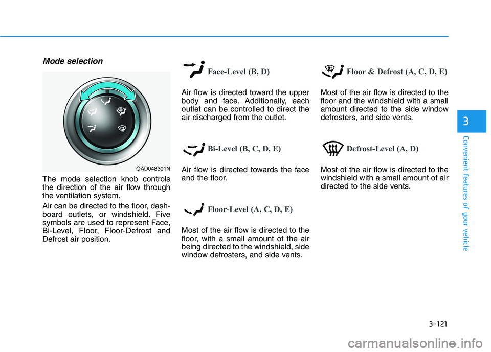
The mode selection knob controls
the direction of the air flow through
the ventilation system.
Air can be directed to the floor, dash-
board outlets, or windshield. Five
symbols are used to represent Face,
Bi-Level, Floor, Floor-Defrost andDefrost air position.
Face-Level (B, D)
Air flow is directed toward the upper
body and face. Additionally, eachoutlet can be controlled to direct theair discharged from the outlet.
Bi-Level (B, C, D, E)
Air flow is directed towards the face
and the floor.
Floor-Level (A, C, D, E)
Most of the air flow is directed to the
floor, with a small amount of the airbeing directed to the windshield, side
window defrosters, and side vents.
Floor & Defrost (A, C, D, E)
Most of the air flow is directed to the floor and the windshield with a small
amount directed to the side window
defrosters, and side vents.
Defrost-Level (A, D)
Most of the air flow is directed to the windshield with a small amount of air
directed to the side vents.OAD048301N
Page 207 of 534
3-122
Convenient features of your vehicle
MAX A/C-Level (B, D) (if equipped)
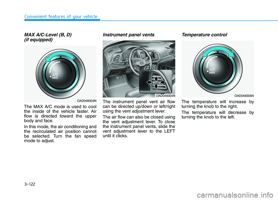
The MAX A/C mode is used to cool
the inside of the vehicle faster. Air
flow is directed toward the upper
body and face.
In this mode, the air conditioning and the recirculated air position cannot
be selected. Turn the fan speedmode to adjust.
Instrument panel vents
The instrument panel vent air flow
can be directed up/down or left/right
using the vent adjustment lever.
The air flow can also be closed using
the vent adjustment lever. To close
the instrument panel vents, slide the
vent adjustment lever to the LEFT
until it clicks.
Temperature control
The temperature will increase by
turning the knob to the right.
The temperature will decrease by
turning the knob to the left.
OAD048305N
OAD048303N
OAD048304N
Page 217 of 534
3-132
Convenient features of your vehicle
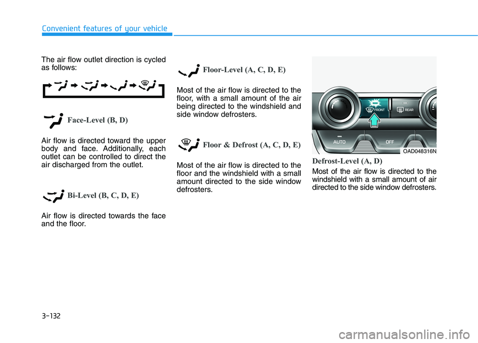
The air flow outlet direction is cycled
as follows:
Face-Level (B, D)
Air flow is directed toward the upper
body and face. Additionally, eachoutlet can be controlled to direct theair discharged from the outlet.
Bi-Level (B, C, D, E)
Air flow is directed towards the face
and the floor.
Floor-Level (A, C, D, E)
Most of the air flow is directed to the
floor, with a small amount of the airbeing directed to the windshield and
side window defrosters.
Floor & Defrost (A, C, D, E)
Most of the air flow is directed to the floor and the windshield with a small
amount directed to the side window
defrosters.Defrost-Level (A, D)
Most of the air flow is directed to the windshield with a small amount of air
directed to the side window defrosters.
OAD048316N
Page 243 of 534
5
Forward Collision Avoidance (FCA) System
(With Hyundai Smart Sense)..............................5-87System Setting and Activation.....................................5-87
FCA Warning Message and System Control ............5-90
FCA Sensor (Front Radar/Front Camera) .................5-92
System Malfunction .......................................................5-94
Limitations of the System .............................................5-96
Lane Keeping Assist (LKA) System .................5-101 LKA System Operation.................................................5-102
Warning Light and Message ......................................5-105
Limitations of the System...........................................5-107
LKA System Function Change ...................................5-109
Driver Attention Warning (DAW) System .......5-110 System Setting and Activation ..................................5-110
Resetting the System ...................................................5-111
System Standby.............................................................5-112
System Malfunction .....................................................5-112
Cruise Control .....................................................5-114 Cruise Control Operation ............................................5-114
Smart Cruise Control System ...........................5-119 Smart Cruise Control Switch ......................................5-120
Smart Cruise Control Speed .......................................5-121
Smart Cruise Control Vehicle-to-Vehicle
Distance ...........................................................................5-125 Sensor to Detect Distance to the
Vehicle Ahead ................................................................5-127
To Adjust the Sensitivity of
Smart Cruise Control ....................................................5-129
To Convert to Cruise Control Mode .........................5-130
Limitations of the System...........................................5-130
Special Driving Conditions ................................5-136 Hazardous Driving Conditions....................................5-136
Rocking the Vehicle ......................................................5-136
Smooth Cornering .........................................................5-137
Driving at Night .............................................................5-137
Driving in the Rain ........................................................5-137
Driving in Flooded Areas.............................................5-138
Highway Driving ............................................................5-138
Winter Driving ....................................................5-139 Snow or Icy Conditions................................................5-139
Winter Precautions .......................................................5-139
Vehicle Load Limit..............................................5-142 Tire Loading Information Label .................................5-143
Trailer Towing .....................................................5-148
Page 248 of 534
5-7
Driving your vehicle
5
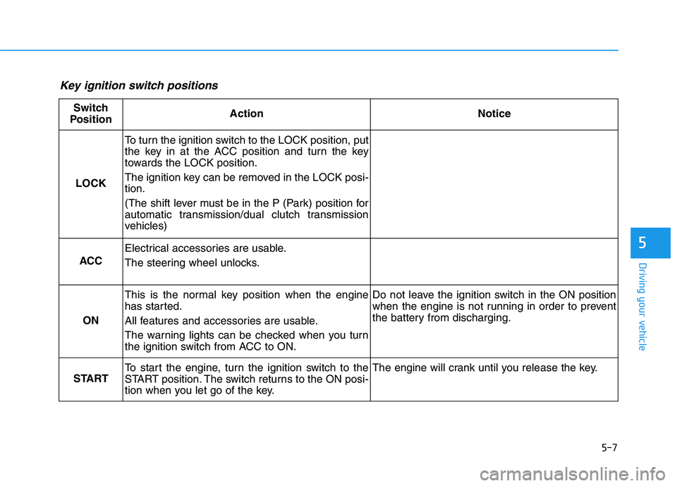
Key ignition switch positions
Switch
PositionActionNotice
LOCK
To turn the ignition switch to the LOCK position, put
the key in at the ACC position and turn the key
towards the LOCK position.
The ignition key can be removed in the LOCK posi- tion.
(The shift lever must be in the P (Park) position for
automatic transmission/dual clutch transmission
vehicles)
ACC
Electrical accessories are usable.
The steering wheel unlocks.
ON
This is the normal key position when the engine
has started.
All features and accessories are usable.
The warning lights can be checked when you turn
the ignition switch from ACC to ON.Do not leave the ignition switch in the ON position
when the engine is not running in order to prevent
the battery from discharging.
START
To start the engine, turn the ignition switch to the
START position. The switch returns to the ON posi-
tion when you let go of the key.The engine will crank until you release the key.
Page 249 of 534
5-8
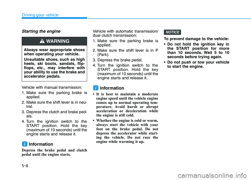
Starting the engine
Vehicle with manual transmission:
1. Make sure the parking brake isapplied.
2. Make sure the shift lever is in neu- tral.
3. Depress the clutch and brake ped- als.
4. Turn the ignition switch to the START position. Hold the key
(maximum of 10 seconds) until the
engine starts and release it.
Information
Depress the brake pedal and clutch
pedal until the engine starts. Vehicle with automatic transmission/
dual clutch transmission:
1. Make sure the parking brake is
applied.
2. Make sure the shift lever is in P (Park).
3. Depress the brake pedal.
4. Turn the ignition switch to the START position. Hold the key
(maximum of 10 seconds) until the
engine starts and release it.
Information
It is best to maintain a moderate engine speed until the vehicle engine
comes up to normal operating tem-
perature. Avoid harsh or abrupt
acceleration or deceleration while
the engine is still cold.
Whether the engine is cold or warm, always start the vehicle with your
foot on the brake pedal. Do not
depress the accelerator while start-
ing the vehicle. Do not race the
engine while warming it up. To prevent damage to the vehicle:
Do not hold the ignition key in
the START position for more
than 10 seconds. Wait 5 to 10
seconds before trying again.
Do not push or tow your vehicle to start the engine.
NOTICE
i
i
Driving your vehicle
Always wear appropriate shoes
when operating your vehicle.
Unsuitable shoes, such as high
heels, ski boots, sandals, flip-
flops, etc., may interfere with
your ability to use the brake andaccelerator pedals.
WARNING
Page 256 of 534
5-15
Driving your vehicle
5
Information
Do not wait for the engine to warm up while the vehicle remains station-
ary. Start driving at moderate
engine speeds. (Aggressive acceler-
ating and decelerating should be
avoided.)
Always start the vehicle with your foot on the brake pedal. Do not
depress the accelerator while start-
ing the vehicle. Do not race the
engine while warming it up.
To prevent damage to the vehicle:
If the engine stalls while you are in motion, do not attempt to
move the shift lever to the P
(Park) position.
If traffic and road conditions
permit, you may put the shift
lever in the N (Neutral) position
while the vehicle is still moving
and press the Engine Start/Stop
button in an attempt to restart
the engine.
Do not push or tow your vehicle to start the engine. To prevent damage to the vehicle:
When the stop lamp switch fuse is
blown, you can't start the engine
normally. Replace the fuse with a
new one. If you are not able to
replace the fuse, you can start the
engine by pressing and holding
the Engine Start/Stop button for10 seconds with the Engine
Start/Stop button in the ACC posi-tion.
Do not press the Engine Start/
Stop button for more than 10 sec-
onds except when the stop lamp
switch fuse is blown.
For your safety always depress
the brake pedal before starting the
engine.
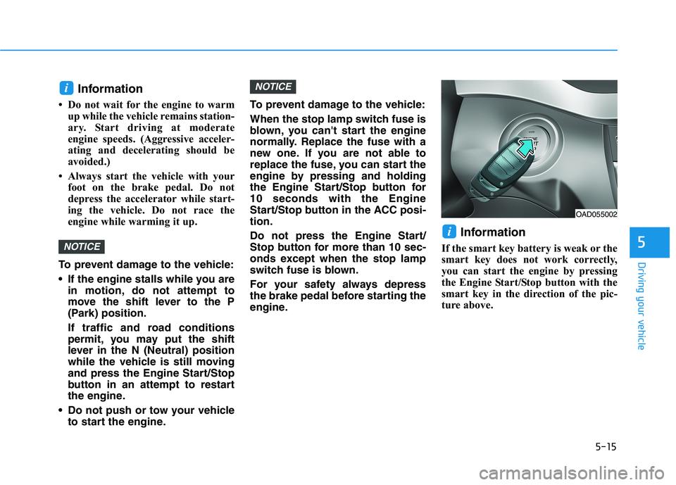
Information
If the smart key battery is weak or the
smart key does not work correctly,
you can start the engine by pressing
the Engine Start/Stop button with the
smart key in the direction of the pic-
ture above.
i
NOTICE
NOTICE
i
OAD055002
Page 322 of 534
5-81
Driving your vehicle
5
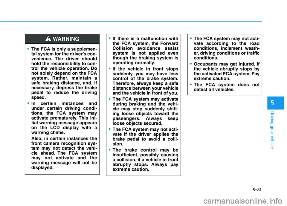
The FCA is only a supplemen-
tal system for the driver’s con-
venience. The driver shouldhold the responsibility to con-
trol the vehicle operation. Do
not solely depend on the FCA
system. Rather, maintain a
safe braking distance, and, if
necessary, depress the brakepedal to reduce the drivingspeed.
In certain instances and
under certain driving condi-
tions, the FCA system may
activate prematurely. This ini-
tial warning message appears
on the LCD display with a
warning chime.
Also, in certain instances the
front camera recognition sys-
tem may not detect the vehi-
cle ahead. The FCA system
may not activate and the
warning message will not be
displayed.
WARNING If there is a malfunction with
the FCA system, the Forward
Collision avoidance assist
system is not applied eventhough the braking system is
operating normally.
If the vehicle in front stops
suddenly, you may have less
control of the brake system.
Therefore, always keep a safe
distance between your vehicle
and the vehicle in front of you.
The FCA system may activate during braking and the vehi-
cle may stop suddenly shift-
ing loose objects toward the
passengers. Always keeploose objects secured.
The FCA system may not acti-
vate if the driver applies the
brake pedal to avoid a colli-sion.
The brake control may be
insufficient, possibly causing
a collision, if a vehicle in front
abruptly stops. Always pay
extreme caution.
The FCA system may not acti-
vate according to the road
conditions, inclement weath-
er, driving conditions or trafficconditions.
Occupants may get injured, if
the vehicle abruptly stops by
the activated FCA system. Pay
extreme caution.
The FCA system does not
detect all vehicles.