2019 HYUNDAI ELANTRA SPORT park assist
[x] Cancel search: park assistPage 291 of 534
5-50
Driving your vehicle
VSM OFF condition
To cancel VSM operation, press the
ESC OFF button. ESC OFF indicator
light ( ) will illuminate.
To turn on VSM, press the ESC OFF
button again. The ESC OFF indicatorlight will go out.
Driving with wheels and tires with dif-
ferent sizes may cause the ESC sys-
tem to malfunction. Before replacing
tires, make sure all four tires and
wheels are the same size. Never
drive the vehicle with different sizedtires and wheels installed.
Hill-Start Assist Control (HAC)
The Hill-Start Assist Control (HAC)
helps prevent the vehicle from rolling
backwards when starting a vehicle
from a stop on a hill. The system
operates the brakes automatically for
approximately 2 seconds and releas-
es the brake after 2 seconds or when
the accelerator pedal is depressed.
The HAC does not operate whenthe shift lever is in P (Park) or N (Neutral)
The HAC activates even though the ESC (Electronic Stability
Control) is off but does not acti-
vate when the ESC has malfunc-tioned.
Good Braking Practices
Wet brakes can be dangerous! The
brakes may get wet if the vehicle is
driven through standing water or if it
is washed. Your vehicle will not stop
as quickly if the brakes are wet. Wet
brakes may cause the vehicle to pull
to one side.
NOTICE
If ESC indicator light ( ) or
EPS warning light ( ) stays on
or blinks, your vehicle may have
a malfunction with the VSM sys-
tem. When the warning light illu-
minates, have your vehicle
checked by an authorized
HYUNDAI dealer as soon as
possible.
WARNING
Always be ready to depress the
accelerator pedal when starting
off on a incline. The HAC acti-
vates only for approximately 2seconds.
WARNING
Whenever leaving the vehicle or
parking, always come to a com-
plete stop and continue to
depress the brake pedal. Move
the shift lever into the 1 st
gear
(for manual transmission vehi-
cle) or P (Park, for automatic
transmission vehicle) position,
then apply the parking brake,
and place the ignition switch inthe LOCK/OFF position.
Vehicles parked with the park- ing brake not applied or not
fully engaged may roll inadver-
tently and may cause injury to
the driver and others. ALWAYS
apply the parking brake before
exiting the vehicle.
WARNING
Page 323 of 534
5-82
Driving your vehicle
Limitations of the System
The Forward Collision Avoidance Assist (FCA) system is designed to
monitor the vehicle ahead on the
roadway through camera recognition
to warn the driver that a collision is
imminent, and if necessary, apply
emergency braking.
In certain situations, the camera may
not be able to detect the vehicle
ahead. In these cases, the FCA sys-
tem may not operate normally. The
driver must pay careful attention in
the following situations where the
FCA operation may be limited.
Detecting vehicles
The sensor may be limited when:
The camera is blocked with a for-eign object or debris
Inclement weather such as heavy rain or snow obscures the field of
view of the camera
There is interference by electro- magnetic waves
The vehicle is on unpaved or uneven rough surfaces, or road
with sudden gradient changes.
The vehicle drives through a con- struction area, on an unpaved
road, or above metal materials,
such as a railway
The vehicle in front is too small to be detected (for example a motor-
cycle or a bicycle, etc.)
The camera's field of view is not well illuminated (either too dark or
too much reflection or too much
backlight that obscures the field of
view)
The camera does not recognize the entire vehicle in front.
The FCA system operates
only to detect vehicles in front
of the vehicle.
The FCA system does not
operate when the vehicle is in
reverse.
The FCA system is not designed to detect other
objects on the road such asanimals.
The FCA system does not
detect vehicles in the oppo-
site lane.
The FCA system does not
detect cross traffic vehicles
that are approaching.
The FCA system cannot
detect the driver approaching
the side view of a parked vehi-
cle (for example on a deadend street).
In these cases, you must main-
tain a safe braking distance,
and if necessary, depress thebrake pedal to reduce the driv-
ing speed in order to maintain a
safe distance.
WARNING
Page 337 of 534
5-96
Driving your vehicle
Limitations of the System
The Forward Collision Avoidance Assist (FCA) system is designed to
monitor the vehicle ahead or a
pedestrian on the roadway through
radar signals and camera recogni-
tion to warn the driver that a collision
is imminent, and if necessary, apply
emergency braking.
In certain situations, the radar sen-
sor or the camera may not be able to
detect the vehicle or pedestrian
ahead. In these cases, the FCA sys-
tem may not operate normally. The
driver must pay careful attention in
the following situations where the
FCA operation may be limited.
Detecting vehicles
The sensor may be limited when:
The radar sensor or camera isblocked with a foreign object or
debris
Inclement weather such as heavy rain or snow obscures the field of
view of the radar sensor or camera
There is interference by electro- magnetic waves The vehicle is on unpaved or
uneven rough surfaces, or road
with sudden gradient changes.
The vehicle drives through a con- struction area, on an unpaved
road, or above metal materials,
such as a railway
The vehicle in front is too small to be detected (for example a motor-
cycle or a bicycle, etc.)
The camera’s field of view is not well illuminated (either too dark or
too much reflection or too much
backlight that obscures the field of
view)
The camera does not recognize the entire vehicle in front.
The vehicle in front is an oversize vehicle or trailer that is too big to
be detected by the camera recog-
nition system (for example a tractor
trailer, etc.)
The vehicle in front does not have rear lights or the rear lights are not
turned ON or the rear lights are
located unusually.
The outside brightness changes suddenly, for example when enter-
ing or exiting a tunnel The vehicle drives inside a build-
ing, such as a basement parkinglot
The adverse road conditions cause excessive vehicle vibrations while
driving
You are on a roundabout and the vehicle in front circles
The camera lens is contaminated due to tinted, filmed or coated
windshield, damaged glass, or
stuck of foreign matter (sticker,
bug, etc.) on the glass
The camera is damaged.
The brightness outside is too low such as when the headlamps are
not on at night or the vehicle isgoing through a tunnel.
Light coming from a street light or an oncoming vehicle is reflected on
a wet road surface such as a pud-dle in the road
The field of view in front is obstructed by sun glare
The shadow is on the road by a median strip, trees, etc.
The vehicle drives through a toll- gate.
Page 392 of 534
6-3
What to do in an emergency
If the Engine Stalls While Driving
Reduce your speed gradually,keeping a straight line. Move cau-
tiously off the road to a safe place.
Turn on your hazard warning flash- er.
Try to start the engine again. If your vehicle will not start, contact an
authorized HYUNDAI dealer or
seek other qualified assistance.
If the Engine Stalls at a
Crossroad or Crossing
If the engine stalls at a crossroad or
crossing, if safe to do so, move the
shift lever to the N (Neutral) position
and then push the vehicle to a safelocation.
If You Have a Flat Tire While Driving
If a tire goes flat while you are driv- ing:
Take your foot off the acceleratorpedal and let the vehicle slow
down while driving straight ahead.
Do not apply the brakes immedi-ately or attempt to pull off the road
as this may cause loss of vehiclecontrol resulting in an accident.
When the vehicle has slowed to
such a speed that it is safe to do
so, brake carefully and pull off the
road. Drive off the road as far as
possible and park on firm, level
ground. If you are on a divided
highway, do not park in the median
area between the two traffic lanes.
When the vehicle is stopped, press the hazard warning flasher button,
move the shift lever into P(Park),
and apply the parking brake, and
place the ignition switch in theLOCK/OFF position.
Have all passengers get out of the vehicle. Be sure they all get out on
the side of the vehicle that is away
from traffic. When changing a flat tire, follow
the instructions provided later in
this chapter.
IINN CC AA SSEE OO FF AA NN EE MM EERR GG EENN CCYY WW HHIILL EE DD RRIIVV IINN GG
6
Page 396 of 534
6-7
What to do in an emergency
6
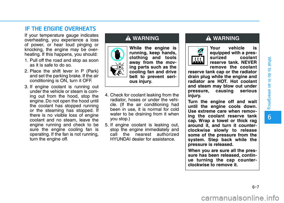
If your temperature gauge indicates
overheating, you experience a loss
of power, or hear loud pinging or
knocking, the engine may be over-
heating. If this happens, you should:
1. Pull off the road and stop as soonas it is safe to do so.
2. Place the shift lever in P (Park) and set the parking brake. If the air
conditioning is ON, turn it OFF.
3. If engine coolant is running out under the vehicle or steam is com-ing out from the hood, stop the
engine. Do not open the hood until
the coolant has stopped running
or the steaming has stopped. If
there is no visible loss of engine
coolant and no steam, leave the
engine running and check to be
sure the engine cooling fan is
operating. If the fan is not running,
turn the engine off. 4. Check for coolant leaking from the
radiator, hoses or under the vehi-
cle. (If the air conditioning had
been in use, it is normal for cold
water to be draining from it when
you stop.)
5. If engine coolant is leaking out, stop the engine immediately and
call the nearest authorized
HYUNDAI dealer for assistance.
IIFF TT HH EE EE NN GGIINN EE OO VVEERR HH EEAA TTSS
While the engine is
running, keep hands,
clothing and tools
away from the mov-
ing parts such as thecooling fan and drive
belt to prevent seri-
ous injury.
WARNING
Your vehicle is equipped with a pres-
surized coolant
reserve tank. NEVER
remove the coolant
reserve tank cap or the radiatordrain plug while the engine and
radiator are HOT. Hot coolant
and steam may blow out under
pressure, causing serious
injury.
Turn the engine off and wait
until the engine cools down.
Use extreme care when remov-
ing the coolant reserve tank
cap. Wrap a towel or thick rag
around it, and turn it counter-
clockwise slowly to release
some of the pressure from the
system. Step back while thepressure is released.
When you are sure all the pres-
sure has been released, contin-ue turning the cap counter-
clockwise to remove it.
WARNING
Page 399 of 534
6-10
What to do in an emergency
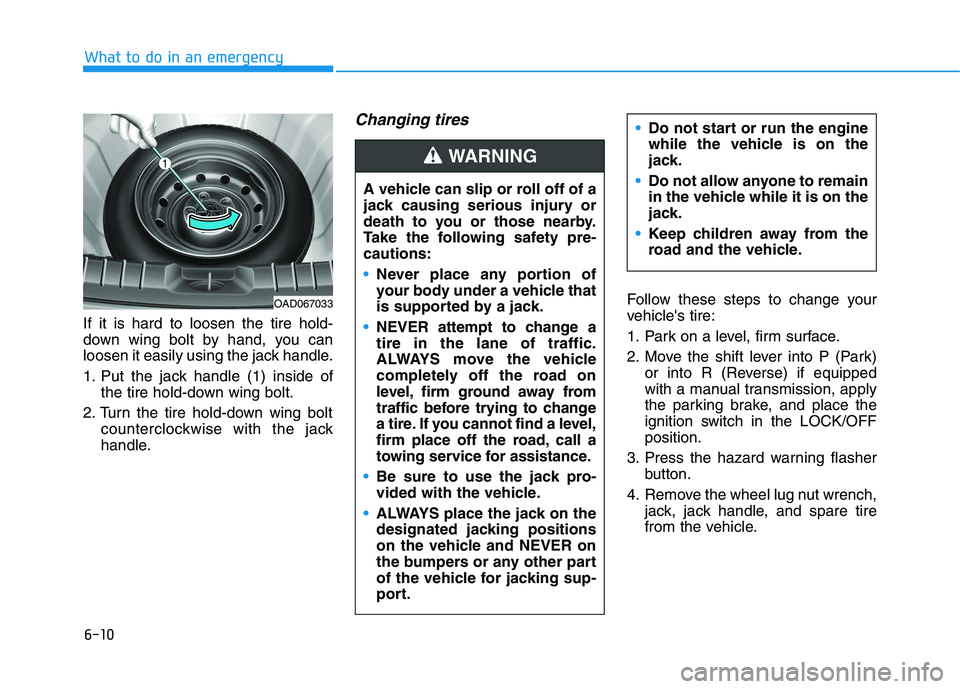
If it is hard to loosen the tire hold-
down wing bolt by hand, you can
loosen it easily using the jack handle.
1. Put the jack handle (1) inside ofthe tire hold-down wing bolt.
2. Turn the tire hold-down wing bolt counterclockwise with the jack
handle.
Changing tires
Follow these steps to change your
vehicle's tire:
1. Park on a level, firm surface.
2. Move the shift lever into P (Park)or into R (Reverse) if equipped
with a manual transmission, apply
the parking brake, and place the
ignition switch in the LOCK/OFFposition.
3. Press the hazard warning flasher button.
4. Remove the wheel lug nut wrench, jack, jack handle, and spare tire
from the vehicle.
A vehicle can slip or roll off of a
jack causing serious injury or
death to you or those nearby.
Take the following safety pre-cautions:
Never place any portion of
your body under a vehicle that
is supported by a jack.
NEVER attempt to change a tire in the lane of traffic.
ALWAYS move the vehicle
completely off the road on
level, firm ground away from
traffic before trying to change
a tire. If you cannot find a level,
firm place off the road, call a
towing service for assistance.
Be sure to use the jack pro-
vided with the vehicle.
ALWAYS place the jack on the
designated jacking positions
on the vehicle and NEVER on
the bumpers or any other part
of the vehicle for jacking sup-
port.
Do not start or run the engine
while the vehicle is on the
jack.
Do not allow anyone to remain
in the vehicle while it is on the
jack.
Keep children away from the
road and the vehicle.
WARNING
OAD067033
Page 486 of 534
7-61
Maintenance
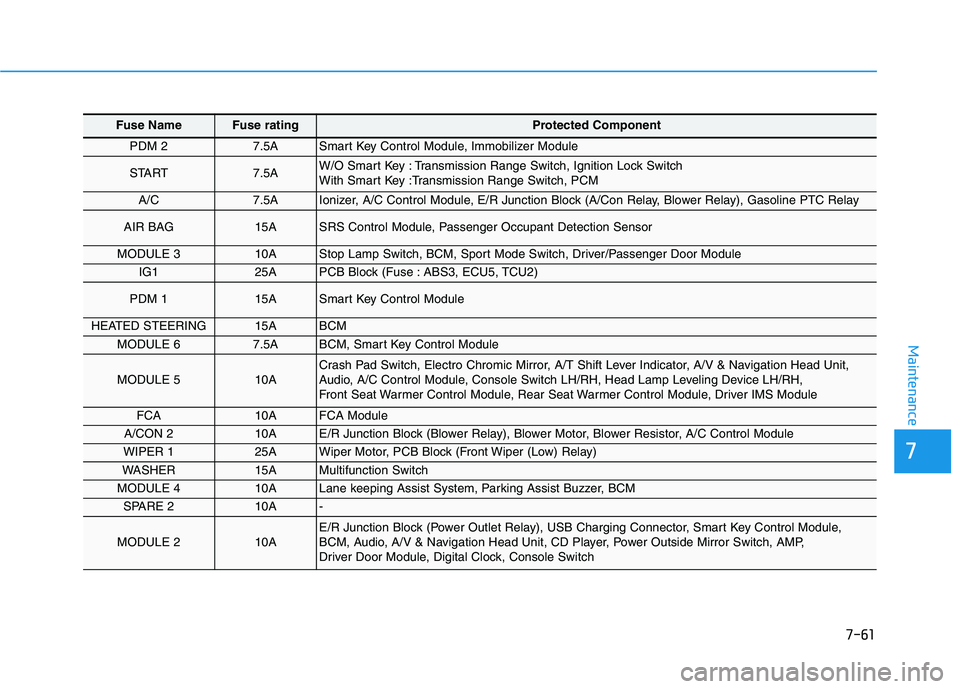
Fuse Name Fuse rating Protected Component
PDM 2 7.5A Smart Key Control Module, Immobilizer Module
START 7.5A W/O Smart Key : Transmission Range Switch, Ignition Lock Switch
With Smart Key :Transmission Range Switch, PCM
A/C7.5A Ionizer, A/C Control Module, E/R Junction Block (A/Con Relay, Blower Relay), Gasoline PTC Relay
AIR BAG 15A SRS Control Module, Passenger Occupant Detection Sensor
MODULE 3 10A Stop Lamp Switch, BCM, Sport Mode Switch, Driver/Passenger Door Module
IG1 25A PCB Block (Fuse : ABS3, ECU5, TCU2)
PDM 1 15A Smart Key Control Module
HEATED STEERING 15A BCM
MODULE 6 7.5A BCM, Smart Key Control Module
MODULE 5 10A Crash Pad Switch, Electro Chromic Mirror, A/T Shift Lever Indicator, A/V & Navigation Head Unit,
Audio, A/C Control Module, Console Switch LH/RH, Head Lamp Leveling Device LH/RH,
Front Seat Warmer Control Module, Rear Seat Warmer Control Module, Driver IMS Module
FCA10A FCA Module
A/CON 2 10A E/R Junction Block (Blower Relay), Blower Motor, Blower Resistor, A/C Control Module
WIPER 1 25A Wiper Motor, PCB Block (Front Wiper (Low) Relay)
WASHER 15A Multifunction Switch
MODULE 4 10A Lane keeping Assist System, Parking Assist Buzzer, BCM
SPARE 2 10A -
MODULE 2 10A E/R Junction Block (Power Outlet Relay), USB Charging Connector, Smart Key Control Module,
BCM, Audio, A/V & Navigation Head Unit, CD Player, Power Outside Mirror Switch, AMP,
Driver Door Module, Digital Clock, Console Switch
7
Page 526 of 534
I-3
Brake/Clutch Fluid..........................................................7-27
Checking the Brake/Clutch Fluid Level.....................7-27
Braking System ...............................................................5-40
Anti-lock Brake System (ABS)..................................5-43
Disc Brakes Wear Indicator........................................5-41
Electronic Stability Control (ESC).............................5-45
Good Braking Practices..............................................5-50
Hill-Start Assist Control (HAC) .................................5-50
Parking Brake .............................................................5-41
Power Brakes..............................................................5-40
Rear drum brakes .......................................................5-41
Vehicle Stability Management (VSM) .......................5-49
Bulb Wattage .....................................................................8-3 Center Console Storage ................................................3-144
Child Restraint System (CRS) ........................................2-33
Children Always in the Rear ......................................2-33
Installing a Child Restraint System (CRS) ................2-36
Selecting a Child Restraint System (CRS).................2-34
Climate Control Additional Features ............................3-143
Automatic Ventilation...............................................3-143
Sunroof Inside Air Recirculation .............................3-143
Climate Control Air Filter...............................................7-31 Filter Inspection..........................................................7-31
Clock .............................................................................3-151
Clothes Hanger .............................................................3-151
Cruise Control ...............................................................5-114 Cruise Control operation ..........................................5-114
Cup Holder....................................................................3-146
Curtain air bags ...............................................................2-48
I
Index
C