2019 HONDA CLARITY ELECTRIC tow
[x] Cancel search: towPage 449 of 559
Continued447
uuCharging uCharge the High Voltage battery using a Level 1, 2 or SAE J1772 DC charger
Driving
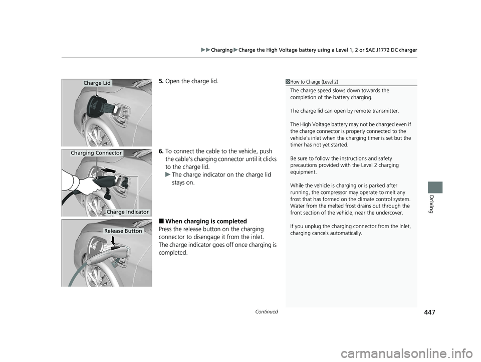
5. Open the charge lid.
6. To connect the cable to the vehicle, push
the cable’s charging conn ector until it clicks
to the charge lid.
u The charge indicator on the charge lid
stays on.
■When charging is completed
Press the release button on the charging
connector to disengag e it from the inlet.
The charge indicator goes off once charging is
completed.
1 How to Charge (Level 2)
The charge speed slows down towards the
completion of the battery charging.
The charge lid can open by remote transmitter.
The High Voltage battery may not be charged even if
the charge connector is properly connected to the
vehicle’s inlet when the charging timer is set but the
timer has not yet started.
Be sure to follow the instructions and safety
precautions provided with the Level 2 charging
equipment.
While the vehicle is charging or is parked after
running, the compressor may operate to melt any
frost that has formed on the climate control system.
Water from the melt ed frost drains out through the
front section of the vehi cle, near the undercover.
If you unplug the charging connector from the inlet,
charging cancels automatically.Charge Lid
Charge Indicator
Charging Connector
Release Button
19 CLARITY BEV-31TRV6200.book 447 ページ 2018年10月29日 月曜日 午前10時54分
Page 450 of 559
uuCharging uCharge the High Voltage battery using a Level 1, 2 or SAE J1772 DC charger
448
Driving
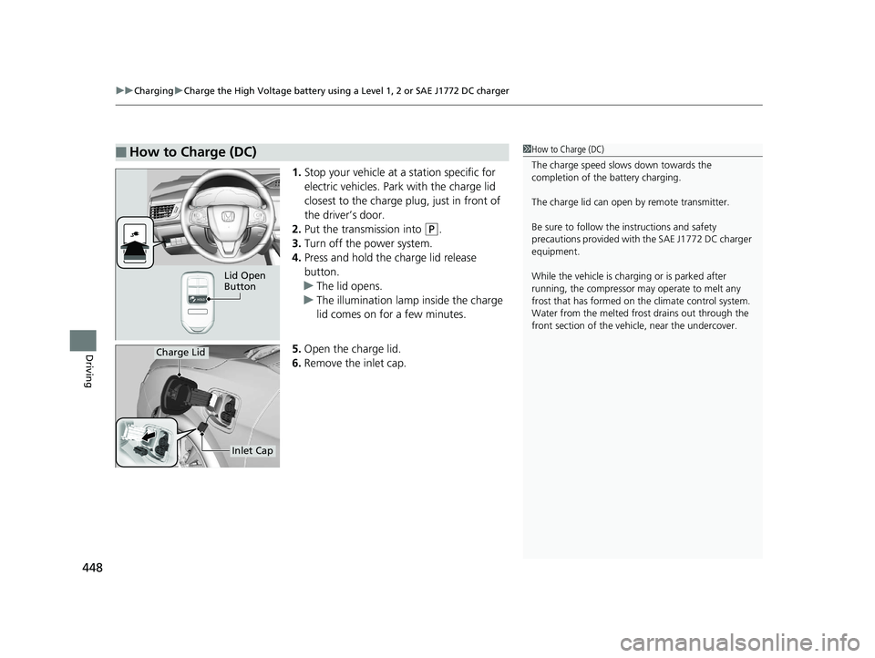
1. Stop your vehicle at a station specific for
electric vehicles. Park with the charge lid
closest to the charge plug, just in front of
the driver’s door.
2. Put the transmission into
(P.
3. Turn off the power system.
4. Press and hold the charge lid release
button.
u The lid opens.
u The illumination lamp inside the charge
lid comes on for a few minutes.
5. Open the charge lid.
6. Remove the inlet cap.
■How to Charge (DC)1How to Charge (DC)
The charge speed slows down towards the
completion of the battery charging.
The charge lid can open by remote transmitter.
Be sure to follow the instructions and safety
precautions provided with the SAE J1772 DC charger
equipment.
While the vehicle is charging or is parked after
running, the compressor may operate to melt any
frost that has formed on the climate control system.
Water from the melt ed frost drains out through the
front section of the vehi cle, near the undercover.
Lid Open
Button
Charge Lid
Inlet Cap
19 CLARITY BEV-31TRV6200.book 448 ページ 2018年10月29日 月曜日 午前10時54分
Page 463 of 559
461
uuBefore Performing Maintenance uSafety When Performing Maintenance
Maintenance
Safety When Performing Maintenance
Some of the most important safe ty precautions are given here.
However, we cannot warn you of every conceivable hazard that can arise in
performing maintenance. Only you can decide whether you should perform a given
task.
• To reduce the possibility of fire or explos ion, keep cigarettes, sparks, and flames
away from the 12-volt battery and all High Voltage system related parts.
• Never leave rags, towels, or other flammable objects under the hood.
u Heat from the motor or the surrounding parts can ignite them, causing a fire.
• To clean parts, use a co mmercially available degreaser or parts cleaner, not
gasoline.
• Wear eye protection and pr otective clothing when working with the 12-volt
battery or compressed air.
• The vehicle must be in a stationary condition.
u Make sure your vehicle is parked on le vel ground, the parking brake is set, and
the power system is turned off.
• Be aware that hot parts can burn you.
u Make sure to let the power system cool thoroughly before touching vehicle
parts.
• Be aware that moving parts can injure you.
u Do not activate the power system unless instructed to do so.
Keep your hands and limbs away from moving parts.
■Maintenance Safety
■Vehicle Safety
1Safety When Performing Maintenance
3WARNING
Improperly maintaining this vehicle or
failing to correct a pr oblem before driving
can cause a crash in which you can be
seriously hurt or killed.
Always follow the inspection and
maintenance recommendations according
to the schedules in this owner’s manual.
3WARNING
Failure to properly follow maintenance
instructions and prec autions can cause you
to be seriously hurt or killed.
Always follow the procedures and
precautions in this owner’s manual.
19 CLARITY BEV-31TRV6200.book 461 ページ 2018年10月29日 月曜日 午前10時54分
Page 470 of 559
468
uuMaintenance Under the Hood uOpening the Hood
Maintenance
Opening the Hood
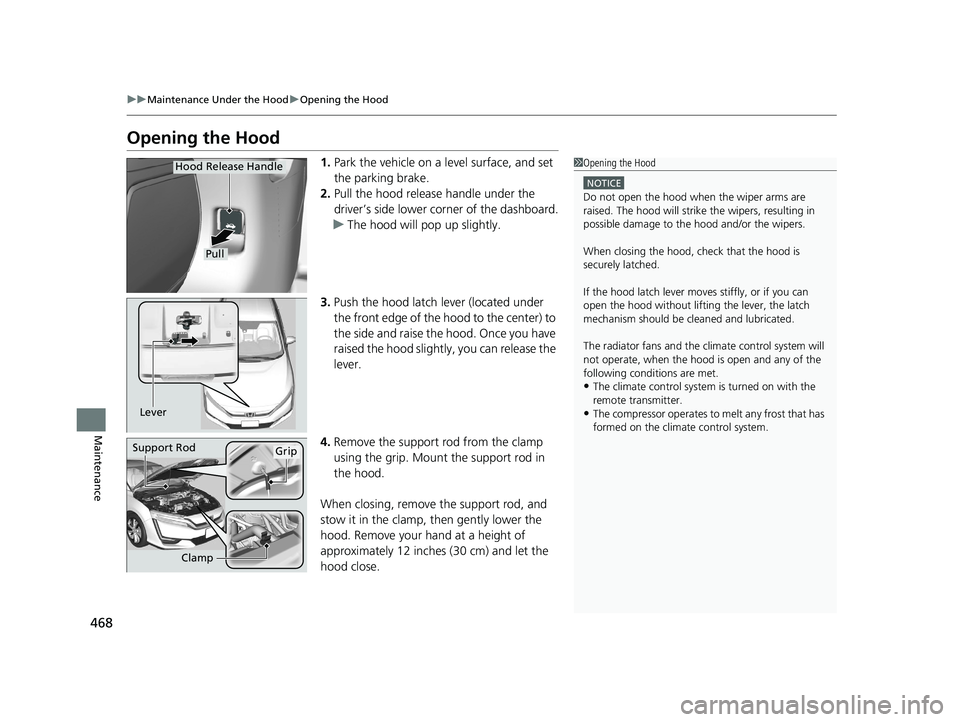
1. Park the vehicle on a level surface, and set
the parking brake.
2. Pull the hood release handle under the
driver’s side lower co rner of the dashboard.
u The hood will pop up slightly.
3. Push the hood latch lever (located under
the front edge of the hood to the center) to
the side and raise the hood. Once you have
raised the hood slight ly, you can release the
lever.
4. Remove the support rod from the clamp
using the grip. Mount the support rod in
the hood.
When closing, remove the support rod, and
stow it in the clamp, then gently lower the
hood. Remove your hand at a height of
approximately 12 inches (30 cm) and let the
hood close.1 Opening the Hood
NOTICE
Do not open the hood when the wiper arms are
raised. The hood will strike the wipers, resulting in
possible damage to the hood and/or the wipers.
When closing the hood, check that the hood is
securely latched.
If the hood latch lever moves stiffly, or if you can
open the hood without lifti ng the lever, the latch
mechanism should be cl eaned and lubricated.
The radiator fans and the climate control system will
not operate, when the hood is open and any of the
following conditions are met.
•The climate control system is turned on with the
remote transmitter.
•The compressor operates to melt any frost that has
formed on the climate control system.
Pull
Hood Release Handle
Lever
Support RodGrip
Clamp
19 CLARITY BEV-31TRV6200.book 468 ページ 2018年10月29日 月曜日 午前10時54分
Page 488 of 559
486
Maintenance
12-Volt Battery
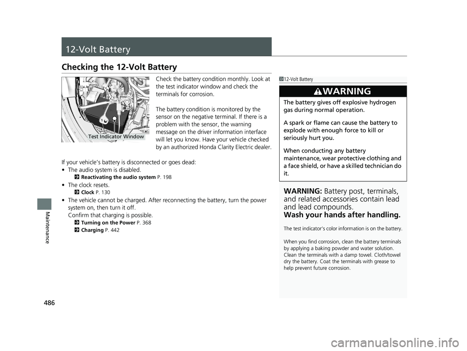
Checking the 12-Volt Battery
Check the battery condition monthly. Look at
the test indicator window and check the
terminals for corrosion.
The battery condition is monitored by the
sensor on the negative terminal. If there is a
problem with the sensor, the warning
message on the driver information interface
will let you know. Have your vehicle checked
by an authorized Honda Clarity Electric dealer.
If your vehicle’s battery is disconnected or goes dead:
• The audio system is disabled.
2 Reactivating the audio system P. 198
•The clock resets.
2 Clock P. 130
•The vehicle cannot be charged. After reconnecting the batte ry, turn the power
system on, then turn it off.
Confirm that charging is possible.
2 Turning on the Power P. 368
2 Charging P. 442
112-Volt Battery
WARNING: Battery post, terminals,
and related accessories contain lead
and lead compounds.
Wash your hands after handling.
The test indicator’s color in formation is on the battery.
When you find corrosion, cl ean the battery terminals
by applying a baking powder and water solution.
Clean the terminals with a damp towel. Cloth/towel
dry the battery. Coat the terminals with grease to
help prevent future corrosion.
3WARNING
The battery gives off explosive hydrogen
gas during normal operation.
A spark or flame can cause the battery to
explode with enough force to kill or
seriously hurt you.
When conducting any battery
maintenance, wear prot ective clothing and
a face shield, or have a skilled technician do
it.
Test Indicator Window
19 CLARITY BEV-31TRV6200.book 486 ページ 2018年10月29日 月曜日 午前10時54分
Page 501 of 559
499
Handling the Unexpected
This chapter explains how to handle unexpected troubles.
If a Tire Goes FlatTemporarily Repairi ng a Flat Tire....... 500
Handling of the Jack ......................... 512
Power System Won’t Start Checking the Procedure ................... 513
If the Smart Entry Remote Battery is Weak .......................................... 514
Emergency Power System Off........... 515
Jump Starting .................................... 516
Overheating How to Handle Overheating ............. 519 Indicator, Coming On/Blinking
If the 12-Volt Battery Charging System Indicator Comes On ....................... 520
If the Brake System Indicator (Red) Comes On or Blinks ....................................... 521
If the Electric Power Steering (EPS) System
Indicator Comes On ........................... 522If the Brake System Indicator (Red) Comes On or Blinks at the Same Time
When the Brake System Indicator
(Amber) Comes On ...................... 523
If the Low Tire Pressure/TPMS Indicator
Comes On or Blinks........................ 524 If the Transmission System Indicator Blinks
along with the Warning Message .... 525
Fuses
Fuse Locations ................................. 526
Inspecting and Changing Fuses ........ 532
Emergency Towing ........................... 533
When You Cannot Open the Charge
Lid ................................................. 534
When You Cannot Disengage the Charging
Connector.................................................535When You Cannot Open the Trunk .. 536
19 CLARITY BEV-31TRV6200.book 499 ページ 2018年10月29日 月曜日 午前10時54分
Page 502 of 559
500
Handling the Unexpected
If a Tire Goes Flat
Temporarily Repairing a Flat Tire
If the tire has a large cut or is otherwise severely damaged, you will need to have the
vehicle towed. If the tire only has a smal l puncture, from a nail for instance, you can
use the temporary tire repair kit so that you can drive to the nearest service station
for a more permanent repair.
If a tire goes flat while driving, grasp the steering wheel firmly, and brake gradually
to reduce speed. Then stop in a safe place.
1. Park the vehicle on a firm, level, and non-slippery surface and apply the parking
brake.
2. Change the gear position to
(P.
3. Turn on the hazard warning lights an d set the power mode to VEHICLE OFF
(LOCK).
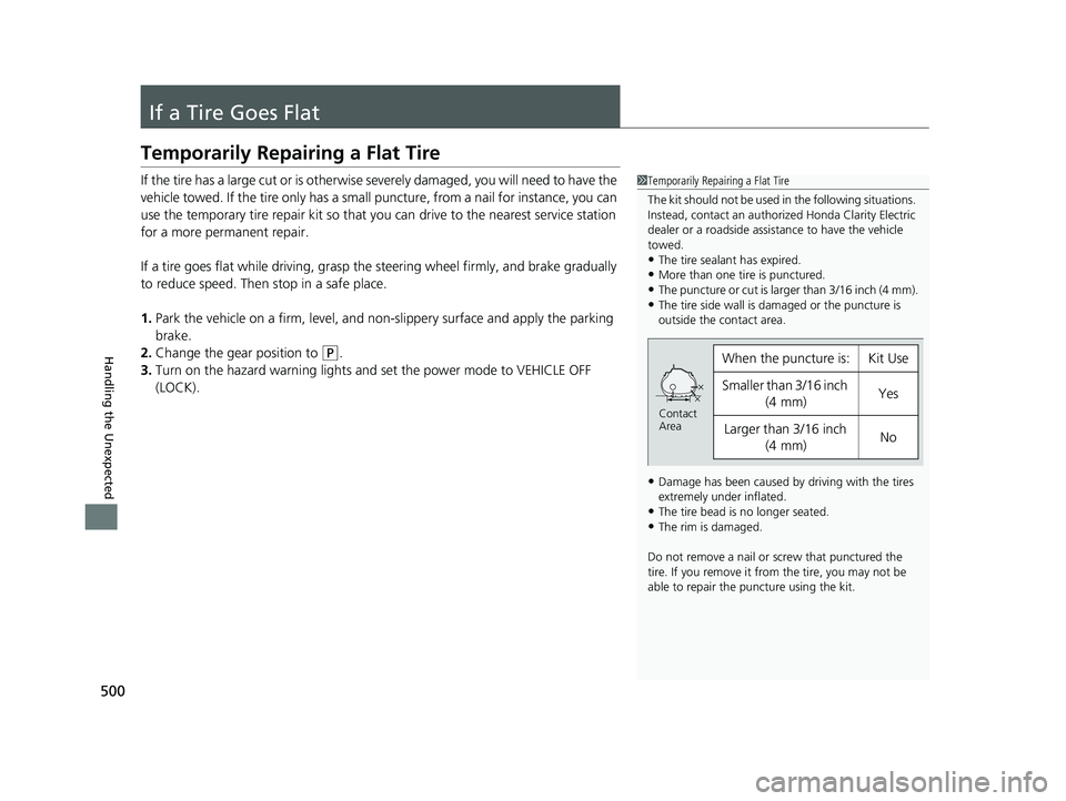
1 Temporarily Repairing a Flat Tire
The kit should not be used in the following situations.
Instead, contact an authorized Honda Clarity Electric
dealer or a roadside assist ance to have the vehicle
towed.
•The tire sealant has expired.•More than one tire is punctured.
•The puncture or cut is larger than 3/16 inch (4 mm).
•The tire side wall is da maged or the puncture is
outside the contact area.
•Damage has been caused by driving with the tires
extremely under inflated.
•The tire bead is no longer seated.•The rim is damaged.
Do not remove a nail or screw that punctured the
tire. If you remove it from the tire, you may not be
able to repair the puncture using the kit.
When the puncture is:Kit Use
Smaller than 3/16 inch (4 mm)Yes
Larger than 3/16 inch
(4 mm)No
Contact
Area
19 CLARITY BEV-31TRV6200.book 500 ページ 2018年10月29日 月曜日 午前10時54分
Page 507 of 559
Continued505
uuIf a Tire Goes Flat uTemporarily Repairing a Flat Tire
Handling the Unexpected
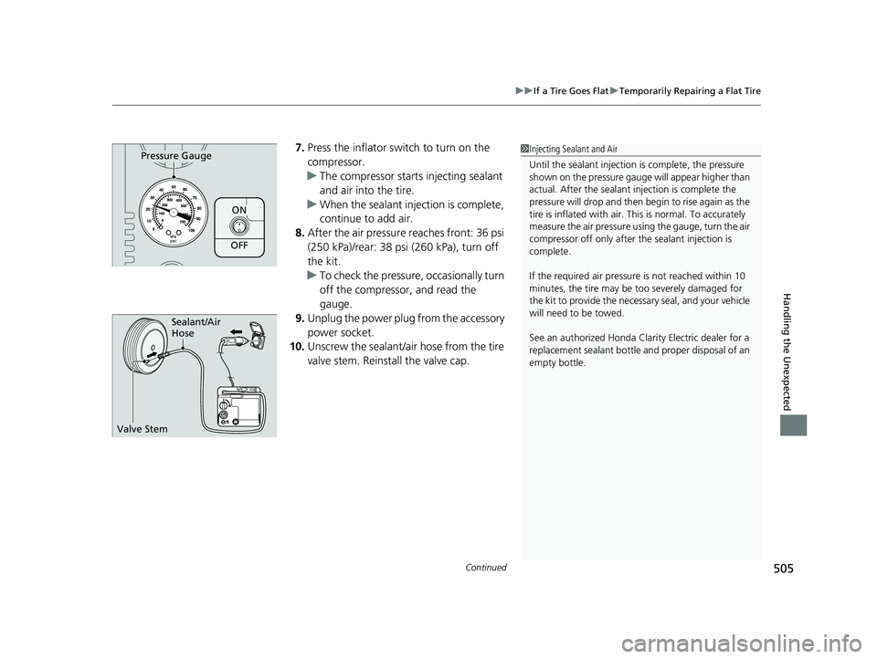
7. Press the inflator switch to turn on the
compressor.
u The compressor starts injecting sealant
and air into the tire.
u When the sealant injection is complete,
continue to add air.
8. After the air pressure reaches front: 36 psi
(250 kPa)/rear: 38 psi (260 kPa), turn off
the kit.
u To check the pressure, occasionally turn
off the compressor, and read the
gauge.
9. Unplug the power plug from the accessory
power socket.
10. Unscrew the sealant/ai r hose from the tire
valve stem. Reinstall the valve cap.
ON
OFF
Pressure Gauge1 Injecting Sealant and Air
Until the sealant injection is complete, the pressure
shown on the pressure gauge will appear higher than
actual. After the sealant injection is complete the
pressure will drop and then begin to rise again as the
tire is inflated with air. This is normal. To accurately
measure the air pressure usi ng the gauge, turn the air
compressor off only after the sealant injection is
complete.
If the required air pressure is not reached within 10
minutes, the tire may be too severely damaged for
the kit to provide the necessa ry seal, and your vehicle
will need to be towed.
See an authorized Honda Clar ity Electric dealer for a
replacement sealant bottle an d proper disposal of an
empty bottle.
Sealant/Air
Hose
Valve Stem
19 CLARITY BEV-31TRV6200.book 505 ページ 2018年10月29日 月曜日 午前10時54分