2019 FORD TAURUS tire type
[x] Cancel search: tire typePage 34 of 515

Pregnant women should always wear their
seatbelt. Position the lap belt portion of a
combination lap and shoulder belt low
across the hips below the belly and worn
as tight as comfort allows. Position the
shoulder belt to cross the middle of the
shoulder and the center of the chest.
Seatbelt Locking Modes
WARNING: If your vehicle is
involved in a crash, have the seatbelts
and associated components inspected
as soon as possible. Failure to follow this
instruction could result in personal injury
or death.
All safety restraints in the vehicle are
combination lap and shoulder belts. The
driver seatbelt has the first type of locking
mode, and the front outboard passenger
and rear seat seatbelts have both types of
locking modes described as follows:
Vehicle Sensitive Mode
This is the normal retractor mode, which
allows free shoulder belt length
adjustment to your movements and
locking in response to vehicle movement.
For example, if the driver brakes suddenly
or turns a corner sharply, or the vehicle
receives an impact of about
5 mph
(8 km/h) or more, the combination
seatbelts lock to help reduce forward
movement of the driver and passengers.
In addition, the design of the retractor is to
lock if you pull the webbing out too quickly.
If the seatbelt retractor locks, slowly lower
the height adjuster to allow the seatbelt
to retract. If the retractor does not unlock,
pull the seatbelt out slowly then feed a small length of webbing back toward the
stowed position. For rear seatbelts, recline
the rear seat backrest or push the seat
backrest cushion away from the seatbelt.
Feed a small length of webbing back
toward the stowed position.
Automatic Locking Mode
In this mode, the shoulder belt
automatically pre-locks. The belt retracts
to remove any slack in the shoulder belt.
The automatic locking mode is not
available on the driver seatbelt.
When to Use the Automatic Locking
Mode
Use this mode any time you install a child
safety seat, except a booster, in passenger
front or rear seating positions. Properly
restrain children 12 years old and under in
a rear seating position whenever possible.
See
Child Safety (page 17).
How to Use the Automatic Locking
Mode 1. Buckle the combination lap and
shoulder belt.
2. Grasp the shoulder portion and pull downward until you pull the entire belt
out. Allow the belt to retract. As the
belt retracts, you will hear a clicking
sound. This indicates the seatbelt is
now in the automatic locking mode.
31
Taurus (CPH) Canada/United States of America, enUSA, Edition date: 201806, First-Printing SeatbeltsE142591
Page 158 of 515
Operating AWD Vehicles With
Mismatched Tires
WARNING: Only use replacement
tires and wheels that are the same size,
load index, speed rating and type (such
as P-metric versus LT-metric or
all-season versus all-terrain) as those
originally provided by Ford. The
recommended tire and wheel size may
be found on either the Safety
Compliance Certification Label (affixed
to either the door hinge pillar, door-latch
post, or the door edge that meets the
door-latch post, next to the driver's
seating position), or the Tire Label which
is located on the B-Pillar or edge of the
driver's door. If this information is not
found on these labels, then you should
contact your authorized dealer as soon
as possible. Use of any tire or wheel not
recommended by Ford can affect the
safety and performance of your vehicle,
which could result in an increased risk of
loss of vehicle control, vehicle rollover,
personal injury and death. WARNING:
The use of
non-recommended tires and wheels
could cause steering, suspension, axle,
transfer case or power transfer unit
failure. If you have questions regarding
tire replacement, contact your
authorized dealer as soon as possible.
Major dissimilar tire sizes between the front
and rear axles (for example, 17 inch low
profile tires on the front axle and 22 inch
high profile tires on the rear axle) could
cause the AWD system to stop functioning
and default to front-wheel drive or damage
the AWD system. However, the AWD system is capable of tolerating any
combination of new and worn tires of the
same original tire size. For example, using
3 worn tread tires and 1 new tread tire all
of the same original tire size, can be
tolerated by the AWD system.
Driving In Special Conditions With
All-Wheel Drive (AWD)
AWD vehicles are equipped for driving on
sand, snow, mud and rough roads and have
operating characteristics that are
somewhat different from conventional
vehicles, both on and off the highway.
When driving at slow speeds in deep sand
under high outside temperatures, use a low
gear when possible. Lower gear operation
will maximize the engine and transmission
cooling capability.
Under severe operating conditions, the A/C
may cycle on and off to protect
overheating of the engine.
Basic operating principles in special
conditions
•
Drive slower in strong crosswinds which
can affect the normal steering
characteristics of your vehicle.
• Be extremely careful when driving on
pavement made slippery by loose sand,
water, gravel, snow or ice.
155
Taurus (CPH) Canada/United States of America, enUSA, Edition date: 201806, First-Printing All-Wheel Drive
(If Equipped)
Page 160 of 515
abrupt steering, acceleration or braking
which could result in an increased risk
of loss of vehicle control, vehicle
rollover and/or personal injury. Use all
available road surface to return the
vehicle to a safe direction of travel.
• In the event of an emergency stop,
avoid skidding the tires and do not
attempt any sharp steering wheel
movements.
• If the vehicle goes from one type of
surface to another (that is, from
concrete to gravel) there will be a
change in the way the vehicle responds
to a maneuver (steering, acceleration
or braking). Again, avoid these abrupt
inputs.
Sand
Most of the time traction control improves
tire traction by managing wheel slip
through Brake, Engine, and AWD
calibrations. However, during low speed
driving, disabling traction control in deep
sand can help keep the wheels moving to
maintain vehicle momentum.
When driving over sand, try to keep all four
wheels on the most solid area of the trail.
Avoid reducing the tire pressures but shift
to a lower gear and drive steadily through
the terrain. Apply the accelerator slowly
and avoid spinning the wheels.
Do not drive your vehicle in deep sand for
an extended period of time. This could
cause the AWD system to overheat and
default to front-wheel drive. If this occurs,
an AWD OFF message displays in the
information display. To resume normal
AWD function as soon as possible, stop
the vehicle in a safe location and stop the
engine for at least 10 minutes. After the
engine has been restarted and the AWD system has adequately cooled, the
AWD
OFF message turns off and normal AWD
function returns. In the event the engine is
not stopped, the AWD OFF message turns
off when the system cools and normal
AWD function returns.
When driving at slow speeds in deep sand
under high outside temperatures, use L
(Low) gear when possible. L (Low) gear
operation will maximize the engine and
transmission cooling capability.
Under severe operating conditions, the A/C
may cycle on and off to protect
overheating of the engine.
Avoid excessive speed because vehicle
momentum can work against you and
cause the vehicle to become stuck to the
point that assistance may be required from
another vehicle. Remember, you may be
able to back out the way you came if you
proceed with caution.
Mud and Water
If you must drive through high water, drive
slowly. Traction or brake capability may
be limited.
When driving through water, determine the
depth; avoid water higher than the bottom
of the wheel rims (for cars) or the bottom
of the hubs (for trucks) (if possible) and
proceed slowly. If the ignition system gets
wet, the vehicle may stall.
Once through water, always try the brakes.
Wet brakes do not stop the vehicle as
effectively as dry brakes. Drying can be
improved by moving your vehicle slowly
while applying light pressure on the brake
pedal.
157
Taurus (CPH) Canada/United States of America, enUSA, Edition date: 201806, First-Printing All-Wheel Drive
(If Equipped)
Page 207 of 515
ESSENTIAL TOWING CHECKS
Follow these guidelines for safe towing:
•
Do not tow a trailer until you drive your
vehicle at least 1,000 mi (1,600 km).
• Consult your local motor vehicle laws
for towing a trailer.
• See the instructions included with
towing accessories for the proper
installation and adjustment
specifications.
• Service your vehicle more frequently if
you tow a trailer. See your scheduled
maintenance information.
• If you use a rental trailer, follow the
instructions the rental agency gives
you.
You can find information on load
specification terms found on the tire label
and Safety Compliance label as well as
instructions on calculating your vehicle's
load in the Load Carrying chapter. See
Load Limit
(page 197).
Remember to account for the trailer
tongue weight as part of your vehicle load
when calculating the total vehicle weight.
Hitches
Do not use a hitch that either clamps onto
the bumper or attaches to the axle.
Distribute the trailer load so 10-15% of the
total trailer weight is on the tongue.
Safety Chains
Note: Never attach safety chains to the
bumper.
Always connect the safety chains to the
hook retainers of your vehicle hitch.
To connect the trailer ’s safety chains, cross
them under the trailer tongue and allow
enough slack for turning tight corners. Do
not allow the chains to drag on the ground. Trailer Brakes WARNING:
Do not connect a
trailer's hydraulic brake system directly
to your vehicle's brake system. Your
vehicle may not have enough braking
power and your chances of having a
collision greatly increase.
Electric brakes and manual, automatic or
surge-type trailer brakes are safe if you
install them properly and adjust them to
the manufacturer's specifications. The
trailer brakes must meet local and federal
regulations.
The rating for the tow vehicle's braking
system operation is at the gross vehicle
weight rating, not the gross combined
weight rating.
Separate functioning brake systems
are required for safe control of towed
vehicles and trailers weighing more
than 1500 pounds (680 kilograms)
when loaded.
Trailer Lamps WARNING:
Never connect any
trailer lamp wiring to the vehicle's tail
lamp wiring; this may damage the
electrical system resulting in fire. Contact
your authorized dealer as soon as
possible for assistance in proper trailer
tow wiring installation. Additional
electrical equipment may be required.
Trailer lamps are required on most towed
vehicles. Make sure all running lights, brake
lights, turn signals and hazard lights are
working.
204
Taurus (CPH) Canada/United States of America, enUSA, Edition date: 201806, First-Printing Towing
Page 266 of 515

GENERAL INFORMATION
The recommended tire inflation pressures
are on the tire information label on the
driver side B-pillar.
Check and set the tire pressure at the
ambient temperature in which you are
intending to drive your vehicle and when
the tires are cold. See Technical
Specifications (page 291).
Note: Check your tire pressures regularly to
optimize fuel economy.
Only use approved wheel and tire sizes.
Using other sizes could damage your
vehicle and could make the National Type
Approval invalid.
Installation of any tires that are not the
original equipment tire size can cause the
speedometer to display incorrect vehicle
speed.
TIRE SEALANT AND INFLATOR
KIT
(If Equipped)
Note: The temporary mobility kit canister
contains enough sealant compound for one
tire repair only. See your authorized Ford
dealer for additional replacement sealant
canisters.
The kit is under the load floor of the trunk.
The kit consists of an air compressor to
inflate the tire and a sealing compound in
a canister that will effectively seal most
punctures caused by nails or similar
objects. This kit will provide a temporary
tire repair allowing you to drive your vehicle
up to
120 mi (200 km) at a maximum
speed of 50 mph (80 km/h) to reach a tire
service location. Air compressor (inside)
A
Diverter knob
B
On and off button
C
Air pressure gauge
D
Sealant bottle and canister
E
Sealant filling clear tube
F
Sealant tube - tire valve
connector
G
Air compressor hose
H
Yellow cap tool
I
Air hose -tire valve connector
J
Accessory power plug
K
Casing/housing
L
263
Taurus (CPH) Canada/United States of America, enUSA, Edition date: 201806, First-Printing Wheels and TiresE144618
Page 272 of 515

TIRE CARE
Information About Uniform
Tire Quality Grading
Tire Quality Grades apply to new
pneumatic passenger car tires.
The Quality grades can be found
where applicable on the tire
sidewall between tread shoulder
and maximum section width. For
example: Treadwear 200
Traction AA Temperature A.
These Tire Quality Grades are
determined by standards that the
United States Department of
Transportation has set.
Tire Quality Grades apply to new
pneumatic passenger car tires.
They do not apply to deep tread,
winter-type snow tires,
space-saver or temporary use
spare tires, light truck or LT type
tires, tires with nominal rim
diameters of 10 to 12 inches or
limited production tires as defined
in Title 49 Code of Federal
Regulations Part 575.104 (c)(2). U.S. Department of
Transportation Tire quality
grades:
The U.S. Department of
Transportation requires Ford
Motor Company to give you the
following information about tire
grades exactly as the government
has written it.
Treadwear
The treadwear grade is a
comparative rating based on the
wear rate of the tire when tested
under controlled conditions on a
specified government test course.
For example, a tire graded 150
would wear 1½ times as well on
the government course as a tire
graded 100. The relative
performance of tires depends
upon the actual conditions of their
use, however, and may depart
significantly from the norm due to
variations in driving habits, service
practices, and differences in road
characteristics and climate.
Traction AA A B C WARNING:
The traction
grade assigned to this tire is
based on straight-ahead braking
traction tests, and does not
include acceleration, cornering,
hydroplaning or peak traction
characteristics.
269
Taurus (CPH) Canada/United States of America, enUSA, Edition date: 201806, First-Printing Wheels and TiresE142542
Page 274 of 515
*kPa: Kilopascal, a metric unit of
air pressure.
*
PSI: Pounds per square inch, a
standard unit of air pressure.
*
Cold tire pressure: The tire
pressure when the vehicle has
been stationary and out of direct
sunlight for an hour or more and
prior to the vehicle being driven for
1 mi (1.6 km)
.
*
Recommended inflation
pressure: The cold inflation
pressure found on the Safety
Compliance Certification Label
(affixed to either the door hinge
pillar, door-latch post, or the door
edge that meets the door-latch
post, next to the driver's seating
position), or Tire Label located on
the B-Pillar or the edge of the
driver door.
* B-pillar: The structural member
at the side of the vehicle behind
the front door.
*
Bead area of the tire: Area of
the tire next to the rim.
*
Sidewall of the tire: Area
between the bead area and the
tread.
*
Tread area of the tire: Area of
the perimeter of the tire that
contacts the road when mounted
on the vehicle.
*Rim: The metal support (wheel)
for a tire or a tire and tube
assembly upon which the tire
beads are seated. Information Contained on the
Tire Sidewall
Both United States and Canada
Federal regulations require tire
manufacturers to place
standardized information on the
sidewall of all tires. This
information identifies and
describes the fundamental
characteristics of the tire and also
provides a U.S. DOT Tire
Identification Number for safety
standard certification and in case
of a recall.
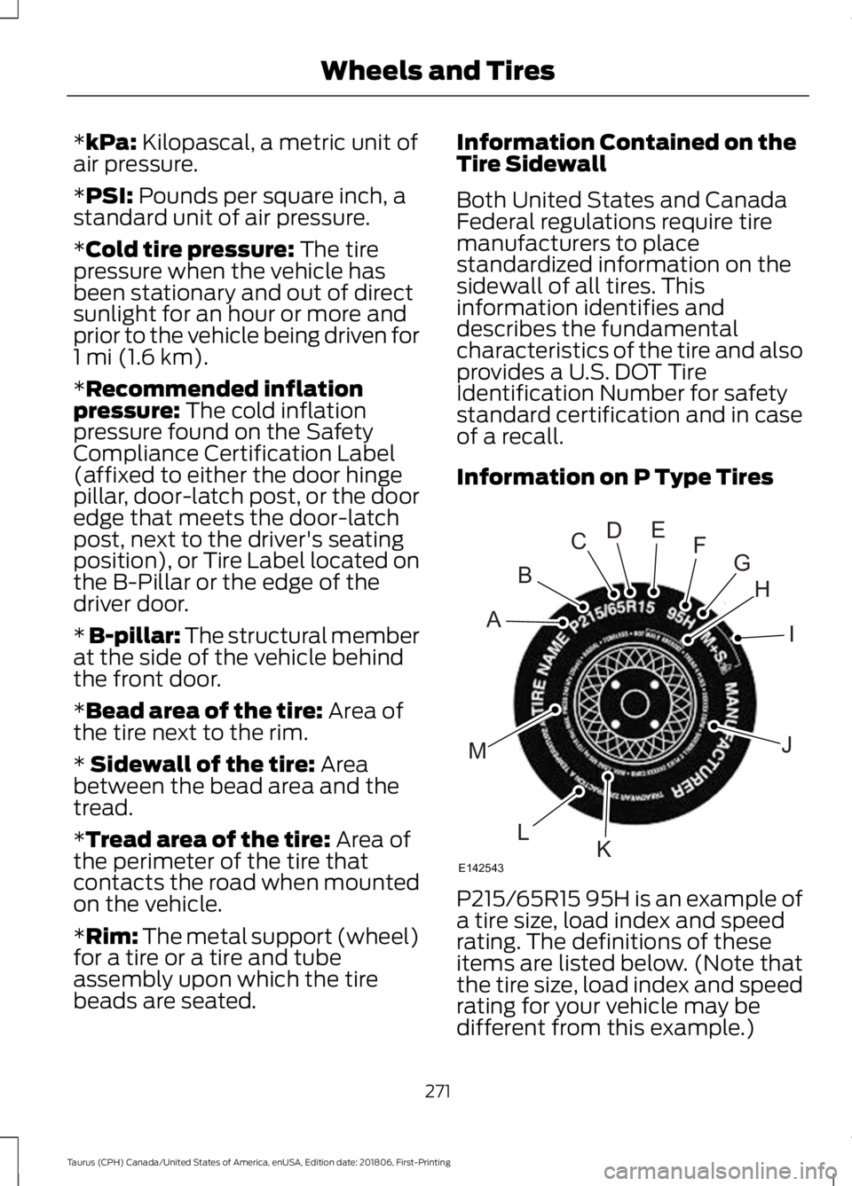
Information on P Type Tires
P215/65R15 95H is an example of
a tire size, load index and speed
rating. The definitions of these
items are listed below. (Note that
the tire size, load index and speed
rating for your vehicle may be
different from this example.)
271
Taurus (CPH) Canada/United States of America, enUSA, Edition date: 201806, First-Printing Wheels and TiresH
I
J
KL
M
A
B
CDEFG
E142543
Page 275 of 515
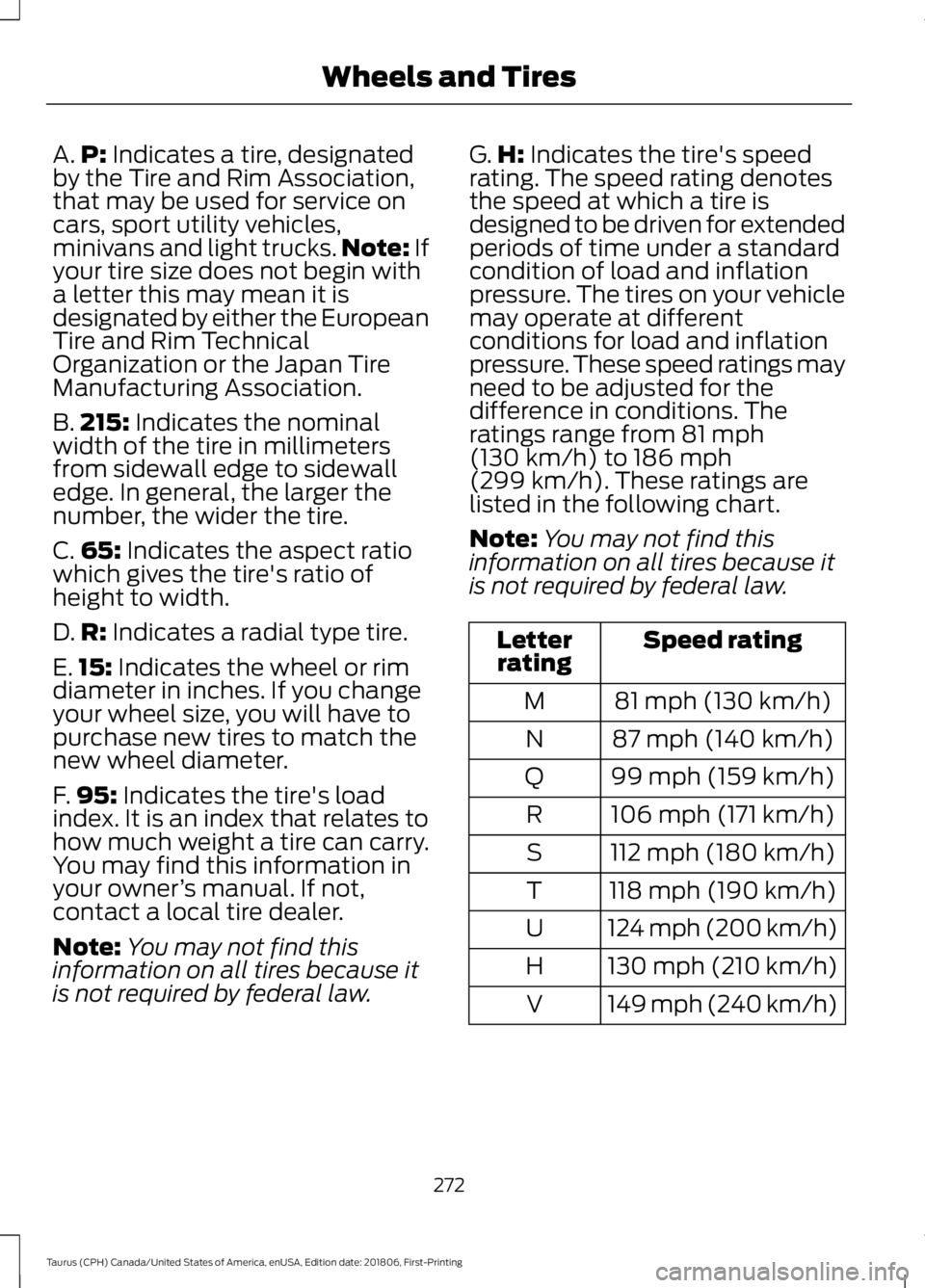
A.
P: Indicates a tire, designated
by the Tire and Rim Association,
that may be used for service on
cars, sport utility vehicles,
minivans and light trucks. Note:
If
your tire size does not begin with
a letter this may mean it is
designated by either the European
Tire and Rim Technical
Organization or the Japan Tire
Manufacturing Association.
B. 215:
Indicates the nominal
width of the tire in millimeters
from sidewall edge to sidewall
edge. In general, the larger the
number, the wider the tire.
C. 65:
Indicates the aspect ratio
which gives the tire's ratio of
height to width.
D. R:
Indicates a radial type tire.
E. 15:
Indicates the wheel or rim
diameter in inches. If you change
your wheel size, you will have to
purchase new tires to match the
new wheel diameter.
F. 95:
Indicates the tire's load
index. It is an index that relates to
how much weight a tire can carry.
You may find this information in
your owner ’s manual. If not,
contact a local tire dealer.
Note: You may not find this
information on all tires because it
is not required by federal law. G.
H:
Indicates the tire's speed
rating. The speed rating denotes
the speed at which a tire is
designed to be driven for extended
periods of time under a standard
condition of load and inflation
pressure. The tires on your vehicle
may operate at different
conditions for load and inflation
pressure. These speed ratings may
need to be adjusted for the
difference in conditions. The
ratings range from
81 mph
(130 km/h) to 186 mph
(299 km/h). These ratings are
listed in the following chart.
Note: You may not find this
information on all tires because it
is not required by federal law. Speed rating
Letter
rating
81 mph (130 km/h)
M
87 mph (140 km/h)
N
99 mph (159 km/h)
Q
106 mph (171 km/h)
R
112 mph (180 km/h)
S
118 mph (190 km/h)
T
124 mph (200 km/h)
U
130 mph (210 km/h)
H
149 mph (240 km/h)
V
272
Taurus (CPH) Canada/United States of America, enUSA, Edition date: 201806, First-Printing Wheels and Tires