2019 FORD F650/750 air condition
[x] Cancel search: air conditionPage 113 of 387
automatically and require no actions from
the driver. During either one of these
regeneration methods, you may notice a
change in exhaust tone. At certain times,
various messages related to the diesel
particulate filter appear in the information
displays.
Oxidation Catalytic Converter and
Diesel Particulate Filter System (If
Equipped) WARNING:
The normal operating
temperature of the exhaust system is
very high. Never work around or attempt
to repair any part of the exhaust system
until it has cooled. Use special care when
working around the diesel oxidation
catalytic converter or the diesel
particulate filter. The diesel oxidation
catalytic converter and the diesel
particulate filter heat up to very high
temperatures after only a short period
of engine operation and remain hot after
you switch the engine off.
Diesel Particulate Filter Maintenance
You must properly maintain your vehicle's
diesel particulate filter in order for it to
function properly.
Do not disregard maintenance messages
that appear in the information display.
Failure to follow the instructions of an
information message may degrade vehicle
performance and could lead to engine
damage that may not be covered by the
vehicle Warranty. Failure to perform active or operator
commanded regeneration when instructed
could result in a clogged diesel particulate
filter. If the diesel particulate filter fills
beyond the regeneration threshold, your
vehicle disables the ability for active and
operator commanded regeneration. This
could result in irreversible damage to the
diesel particulate filter requiring
replacement that may not be covered by
the vehicle Warranty.
Passive Regeneration
In passive regeneration, the exhaust
system temperature and constituents
automatically clean the filter by oxidizing
the soot. Cleaning automatically occurs
during normal vehicle operating conditions
due to driving patterns.
Active Regeneration
Once the diesel particulate filter is full of
exhaust particles, the engine control
module commands the exhaust system to
clean the filter through active regeneration.
Active regeneration requires the engine
computer to raise the exhaust temperature
to eliminate the particles. During cleaning,
the particles convert to harmless gasses.
Once cleaned the diesel particulate filter
continues trapping exhaust particles.
The regeneration process operates more
efficiently when you drive your vehicle at
a constant speed above
30 mph
(48 km/h) and at a steady engine speed
for approximately 20 minutes. The
frequency and duration of regeneration
fluctuates by how you drive your vehicle,
outside air temperature and altitude. For
most driving, regeneration frequency varies
from 100–500 mi (160–805 km) between
occurrences and each occurrence lasts
9– 35 minutes. You can usually reduce the
duration of regeneration if you maintain a
constant speed above 30 mph (48 km/h).
110
F650750 (TBC) , enUSA, Edition date: 201804, Second-Printing Engine Emission Control
Page 122 of 387
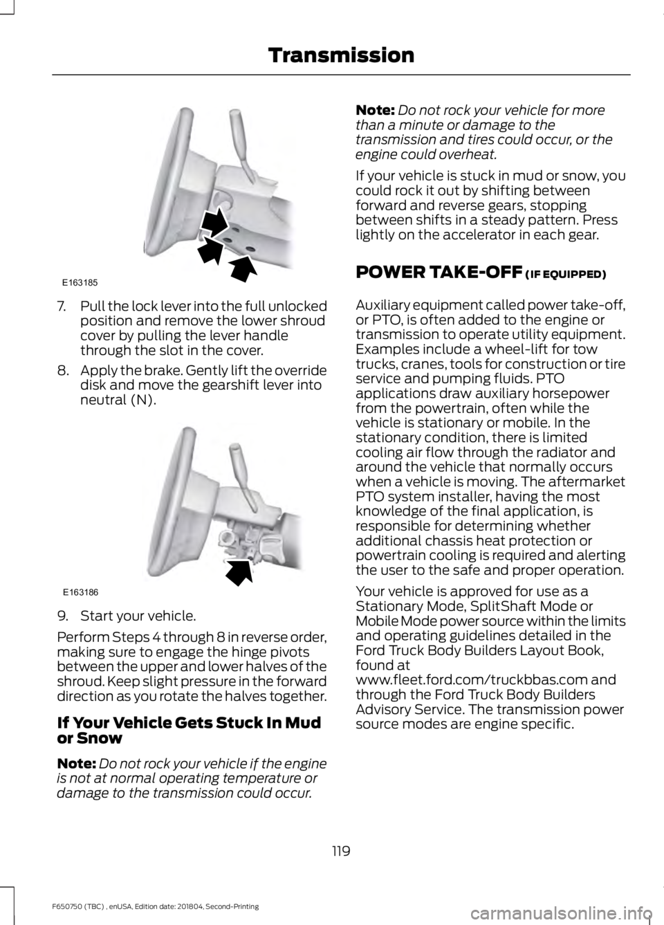
7.
Pull the lock lever into the full unlocked
position and remove the lower shroud
cover by pulling the lever handle
through the slot in the cover.
8. Apply the brake. Gently lift the override
disk and move the gearshift lever into
neutral (N). 9. Start your vehicle.
Perform Steps 4 through 8 in reverse order,
making sure to engage the hinge pivots
between the upper and lower halves of the
shroud. Keep slight pressure in the forward
direction as you rotate the halves together.
If Your Vehicle Gets Stuck In Mud
or Snow
Note:
Do not rock your vehicle if the engine
is not at normal operating temperature or
damage to the transmission could occur. Note:
Do not rock your vehicle for more
than a minute or damage to the
transmission and tires could occur, or the
engine could overheat.
If your vehicle is stuck in mud or snow, you
could rock it out by shifting between
forward and reverse gears, stopping
between shifts in a steady pattern. Press
lightly on the accelerator in each gear.
POWER TAKE-OFF (IF EQUIPPED)
Auxiliary equipment called power take-off,
or PTO, is often added to the engine or
transmission to operate utility equipment.
Examples include a wheel-lift for tow
trucks, cranes, tools for construction or tire
service and pumping fluids. PTO
applications draw auxiliary horsepower
from the powertrain, often while the
vehicle is stationary or mobile. In the
stationary condition, there is limited
cooling air flow through the radiator and
around the vehicle that normally occurs
when a vehicle is moving. The aftermarket
PTO system installer, having the most
knowledge of the final application, is
responsible for determining whether
additional chassis heat protection or
powertrain cooling is required and alerting
the user to the safe and proper operation.
Your vehicle is approved for use as a
Stationary Mode, SplitShaft Mode or
Mobile Mode power source within the limits
and operating guidelines detailed in the
Ford Truck Body Builders Layout Book,
found at
www.fleet.ford.com/truckbbas.com and
through the Ford Truck Body Builders
Advisory Service. The transmission power
source modes are engine specific.
119
F650750 (TBC) , enUSA, Edition date: 201804, Second-Printing TransmissionE163185 E163186
Page 123 of 387
GENERAL INFORMATION
WARNING: Exceeding these
ratings by overloading can cause
component failure resulting in property
damage, personal injury or death.
Fluid Temperature
If the operating temperature exceeds
250°F (121°C)
, the rate of axle lubrication
oxidation increases and shortens the life
of the lubricant and seals, requiring axle
lubrication changes to become more
frequent to preserve the axle. Do not
consistently run extreme pressure (EP)
lubricants above
250°F (121°C).
Axle Conversions WARNING:
When operating a
loaded vehicle, the driver must keep all
adjustable axles on the ground at all
times, supporting their share of the
vehicle ’s load. Failure to do so can
overload other axles, tires, wheels,
springs, steering components, brakes
and frames, resulting in early component
failure, loss of vehicle control, possible
property damage and personal injury.
We do not recommend, or approve,
performing axle conversions. However, we
understand that, on occasion, others install
aftermarket add-on axles on the truck
chassis that allow operator control for
weight transfer from other axles (such as
air lift axles). LIMITED SLIP DIFFERENTIAL
(IF EQUIPPED) WARNING:
If both wheels are not
raised off the ground, the one wheel that
is not raised may pull the vehicle off its
support, possibly resulting in personal
injury.
This axle provides added traction on
slippery surfaces, particularly when one
wheel is on a poor traction surface. Under
normal conditions, the limited-slip axle
functions like a standard rear axle. The axle
may exhibit a slight noise or vibration
during tight turns with low vehicle speed.
This is normal behavior and indicates the
axle is working.
Both wheels must be raised off the ground
should it be necessary to operate one
wheel with your vehicle stationary.
ELECTRONIC LOCKING
DIFFERENTIAL
(IF EQUIPPED)
Driver-Controlled Locking
Differential
Note: Never use the differential lock at
vehicle speeds above
25 mph (40 km/h).
Some drive axles have a driver-controlled
differential lock. The differential lock can
lock or unlock the differential when your
vehicle is moving or stopped. When extra
traction is required, the differential lock
provides full power to both wheels.
When you lock the differential, your
vehicle ’s turning radius increases
(under-steer).
Take care to avoid sudden accelerations
when both drive wheels are on a slippery
surface.
120
F650750 (TBC) , enUSA, Edition date: 201804, Second-Printing Rear Axle
Page 125 of 387
GENERAL INFORMATION
WARNING: Do not apply the brake
pedal and accelerator pedal
simultaneously. Applying both pedals
simultaneously for more than a few
seconds will limit engine performance,
which may result in difficulty maintaining
speed in traffic and could lead to serious
injury.
Note: Occasional brake noise is normal. If
a metal-to-metal, continuous grinding or
continuous squeal sound is present, the
brake linings may be worn-out. Have the
system checked as soon as possible. If your
vehicle has continuous vibration or shudder
in the steering wheel while braking, have it
checked by an authorized dealer.
All standard equipment brakes are
self-adjusting. Automatic adjustment,
when required, occurs whenever you apply
and release the brakes during forward or
reverse operation.
Know the required stopping distances for
all driving conditions you may encounter.
For longer brake lining life, take full
advantage of engine braking power when
coming to a stop.
Wet brakes result in reduced braking
efficiency. Gently press the brake pedal a
few times when driving from a car wash or
standing water to dry the brakes.
If the brakes do not grip well:
• Check brake adjustment.
• Check the brake linings for excessive
wear.
• Check the system air pressure on
vehicles with air brakes. •
Let the brakes cool if you have been
using them excessively, as in mountain
driving or after several fast, high-speed
stops.
• If you have been driving through deep
water, gently apply the brakes several
times while your vehicle is moving
slowly.
Brake Over Accelerator
In the event the accelerator pedal
becomes stuck or entrapped, apply steady
and firm pressure to the brake pedal to
slow the vehicle and reduce engine power.
If you experience this condition, apply the
brakes and bring your vehicle to a safe
stop. Move the transmission to park (P),
switch the engine off and apply the parking
brake. Inspect the accelerator pedal for
any interference. If none are found and the
condition persists, have your vehicle towed
to the nearest authorized dealer
Anti-lock Brake System
This system helps you maintain steering
control during emergency stops by keeping
the brakes from locking. This lamp momentarily
illuminates when you switch the
ignition on. If the light does not
illuminate during start up, remains on or
flashes, the system may be disabled. Have
the system checked by an authorized
dealer. If you connect a PLC trailer with
the ignition on, the trailer ABS
light also illuminates. If the light
fails to illuminate, if it remains on after you
start the vehicle or continues to flash, have
the system serviced immediately.
See
Warning Lamps and Indicators
(page 60).
122
F650750 (TBC) , enUSA, Edition date: 201804, Second-Printing Brakes E210335
Page 128 of 387
Releasing the Parking Brake
WARNING: When your vehicle is
stationary, keep the brake pedal fully
pressed when shifting gears. Failure to
follow this instruction could result in
personal injury, death or property
damage.
Note: Read and understand the following
steps and perform them whenever you
prepare to drive the vehicle.
Note: The parking brake does not disengage
unless sufficient system air pressure is
available.
1. Press and hold the service brake pedal
while the engine is running.
2. Select the appropriate drive gear.
3. Push and hold the yellow dash-mounted parking brake knob until
the parking brake light turns off, then
release.
Parking Brake Light Illumination Due
to Low Air Pressure
If the air pressure becomes too low at any
time during vehicle operation, the parking
brake may apply and the parking brake
light turns on.
If the parking brake applies due to low air
pressure, immediate service is required to
the parking brake system.
Releasing Spring Brake with Air
Pressure
The air system in all vehicles with
spring-actuated rear wheel parking brakes
has a valve on the governor for connection
to an outside air supply. The valve lets you
recharge the system with air from an
outside source, releasing the
spring-actuated parking brakes. Your
vehicle is now ready to tow in an
emergency. You can only use an outside air source if
the protected system is in operating
condition. If you cannot restore air pressure
in the protected air system, you must
release the spring-actuated brakes
manually.
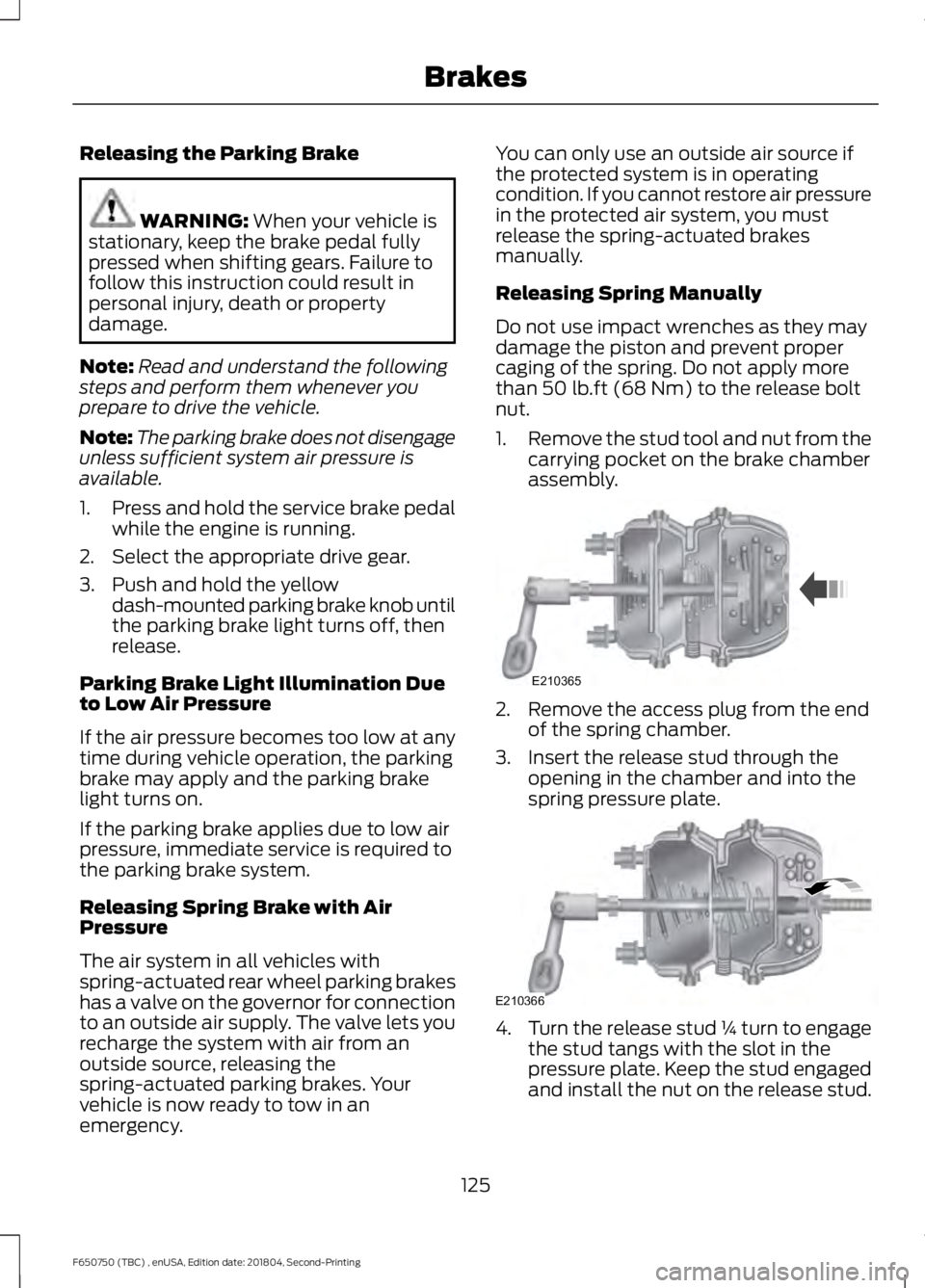
Releasing Spring Manually
Do not use impact wrenches as they may
damage the piston and prevent proper
caging of the spring. Do not apply more
than
50 lb.ft (68 Nm) to the release bolt
nut.
1. Remove the stud tool and nut from the
carrying pocket on the brake chamber
assembly. 2. Remove the access plug from the end
of the spring chamber.
3. Insert the release stud through the opening in the chamber and into the
spring pressure plate. 4.
Turn the release stud ¼ turn to engage
the stud tangs with the slot in the
pressure plate. Keep the stud engaged
and install the nut on the release stud.
125
F650750 (TBC) , enUSA, Edition date: 201804, Second-Printing BrakesE210365 E210366
Page 129 of 387
5. Tighten the nut until the spring is fully
caged and brakes released. Do not
loosen or remove the release stud and
nut unless you completely assemble
and securely clamp the brake chamber.
6. After restoring the air pressure, unscrew and remove the release stud
and install in the carrying pocket. Install
the access plug.
AIR BRAKES (IF EQUIPPED) WARNING:
Do not drive or
continue to drive if the low air pressure
buzzer is sounding or the brake warning
light is lit. These warnings indicate that
air pressure is not to normal operating
level. Continued use of the vehicle could
result in loss of braking ability. WARNING:
Avoid repeated light
application of the brake pedal. This
depletes air pressure faster and could
result in loss of braking capability. WARNING:
Do not move the
vehicle when the air pressure is
insufficient because the brake system
may be inoperative.
After starting the engine, give the air
compressor time to build up the air
pressure to
60 psi (414 kPa) before moving
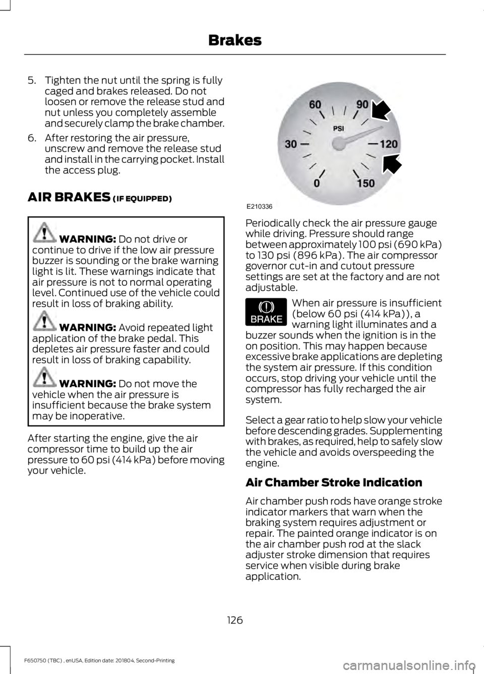
your vehicle. Periodically check the air pressure gauge
while driving. Pressure should range
between approximately 100 psi (690 kPa)
to
130 psi (896 kPa). The air compressor
governor cut-in and cutout pressure
settings are set at the factory and are not
adjustable. When air pressure is insufficient
(below
60 psi (414 kPa)), a
warning light illuminates and a
buzzer sounds when the ignition is in the
on position. This may happen because
excessive brake applications are depleting
the system air pressure. If this condition
occurs, stop driving your vehicle until the
compressor has fully recharged the air
system.
Select a gear ratio to help slow your vehicle
before descending grades. Supplementing
with brakes, as required, help to safely slow
the vehicle and avoids overspeeding the
engine.
Air Chamber Stroke Indication
Air chamber push rods have orange stroke
indicator markers that warn when the
braking system requires adjustment or
repair. The painted orange indicator is on
the air chamber push rod at the slack
adjuster stroke dimension that requires
service when visible during brake
application.
126
F650750 (TBC) , enUSA, Edition date: 201804, Second-Printing BrakesE210336 E206772
Page 136 of 387
PRINCIPLE OF OPERATION
The traction control system helps avoid
drive wheel spin and loss of traction.
If your vehicle begins to slide, the system
applies the brakes to individual wheels
and, when needed, reduces engine power
at the same time. If the wheels spin when
accelerating on slippery or loose surfaces,
the system reduces engine power in order
to increase traction.
Note:
The system does not apply the brakes
when vehicle speed is above 25 mph
(40 km/h).
USING TRACTION CONTROL -
VEHICLES WITH: AIR BRAKES WARNING:
The stability and
traction control light illuminates steadily
if the system detects a failure. Make sure
you did not manually disable the traction
control system using the information
display controls or the switch. If the
stability control and traction control light
is still illuminating steadily, have the
system serviced by an authorized dealer
immediately. Operating your vehicle with
the traction control disabled could lead
to an increased risk of loss of vehicle
control, vehicle rollover, personal injury
and death.
Press the TCS Off button to enable the
mud/snow mode.
This is beneficial when your vehicle is stuck
in snow or on a slippery road surface. This
mode allows wheel spin to dig your vehicle
out and allows you to rock your vehicle.
Press the switch again to select standard
traction control. The system automatically
selects standard traction control at the
next ignition cycle. System Indicator Light
Note:
If the traction control light does not
flash during a traction control event or stays
illuminated, the system is not functioning
properly. Take your vehicle to an authorized
dealer for service.
During traction control operation, the
traction control light flashes rapidly and
the engine does not rev-up when you press
further on the accelerator. This is normal
and is no reason for concern.
In Mud/Snow mode, the TCS OFF light
illuminates on the instrument cluster. If a
traction event occurs in either mode, the
Stability Control and Traction Control light
flashes rapidly.
USING TRACTION CONTROL -
VEHICLES WITH: HYDRAULIC
BRAKES WARNING:
Aggressive driving in
any road conditions can cause you to
lose control of your vehicle increasing
the risk of severe personal injury or
property damage. The occurrence of a
traction control event is an indication
that at least some of the tires have
exceeded their ability to grip the road;
this may lead to an increased risk of loss
of vehicle control, vehicle rollover,
personal injury and death. If you
experience a severe road event, SLOW
DOWN.
The system automatically turns on each
time you switch the ignition on.
Use the traction control switch on the
instrument panel to switch the system off
or on.
133
F650750 (TBC) , enUSA, Edition date: 201804, Second-Printing Traction Control
(If Equipped)
Page 138 of 387
PRINCIPLE OF OPERATION
WARNING: Vehicle modifications
involving braking system, aftermarket
roof racks, suspension, steering system,
tire construction and wheel and tire size
may change the handling characteristics
of your vehicle and may adversely affect
the performance of the electronic
stability control system. In addition,
installing any stereo loudspeakers may
interfere with and adversely affect the
electronic stability control system. Install
any aftermarket stereo loudspeaker as
far as possible from the front center
console, the tunnel, and the front seats
in order to minimize the risk of interfering
with the electronic stability control
sensors. Reducing the effectiveness of
the electronic stability control system
could lead to an increased risk of loss of
vehicle control, vehicle rollover, personal
injury and death. WARNING:
Remember that even
advanced technology cannot defy the
laws of physics. It's always possible to
lose control of a vehicle due to
inappropriate driver input for the
conditions. Aggressive driving on any
road condition can cause you to lose
control of your vehicle increasing the risk
of personal injury or property damage.
Activation of the electronic stability
control system is an indication that at
least some of the tires have exceeded
their ability to grip the road; this could
reduce the operator's ability to control
the vehicle potentially resulting in a loss
of vehicle control, vehicle rollover,
personal injury and death. If your
electronic stability control system
activates, SLOW DOWN.
The system automatically turns on each
time you switch the ignition on. If a fault occurs in either the stability
control or the traction control system, you
may experience the following conditions:
•
The stability and traction control light
illuminates steadily.
• The stability control and traction
control systems do not enhance your
vehicle's ability to maintain traction of
the wheels.
Vehicles With: Air Brakes
If a driving condition activates either the
stability control or the traction control
system you may experience the following
conditions:
• The stability and traction control light
flashes rapidly.
• Your vehicle slows down.
• Reduced engine power.
The stability control system has several
features built into it to help you maintain
control of your vehicle:
Electronic Stability Control
The system enhances your vehicle ’s ability
to prevent skids or lateral slides by
applying brakes to one or more of the
wheels individually and, if necessary,
reducing engine power.
Roll Stability Control
The system enhances your vehicle ’s ability
to prevent rollovers by detecting your
vehicle ’s motion and the rate at which it
changes by applying the brakes to one or
more wheels individually.
Traction Control
The system enhances your vehicle ’s ability
to maintain traction of the wheels by
detecting and controlling wheel spin.
See
Using Traction Control (page 133).
135
F650750 (TBC) , enUSA, Edition date: 201804, Second-Printing Stability Control
(If Equipped)