2019 FORD F650/750 steering wheel
[x] Cancel search: steering wheelPage 115 of 387

Before you start operator commanded
regeneration, do the following:
•
Shift into park (P) or if you have an
RNDM selector shift into neutral (N)
and apply the parking and or air brake,
on stable, level ground.
• Park your vehicle outside of any
structure.
• Park your vehicle 10– 15 ft (3–5 m)
away from any obstructions and away
from materials that can easily combust
or melt, for example paper, leaves,
petroleum products, fuels, plastics and
other dry organic material.
• Make sure there is a minimum of 1/8
tank of fuel.
• Make sure all fluids are at proper levels.
How to Start Operator Commanded
Regeneration WARNING:
Stay clear of the
exhaust tailpipe during regeneration. Hot
exhaust gases can burn you badly.
Note: You cannot use the operator
commanded regeneration until the diesel
particulate filter load percentage has
reached 100%. The diesel particulate filter
load percentage fluctuates up and down
when driving your vehicle due to active and
passive regenerations.
Note: During the use of operator
commanded regeneration, you may observe
a light amount of white smoke. This is
normal. You may not be able to use
operator commanded
regeneration if the service engine
soon warning lamp appears in the
information display Information Display Procedure
Start your vehicle engine and when it has
reached the normal operating temperature,
press the information display control
button on the steering wheel until Exhaust
Filter XX%/FULL is displays. Operator
commanded regeneration can only be
initiated when FULL
See Information
Display Control (page 47). If a message
advising that the exhaust filter is full
appears in the information display, press
the down arrow button to set the display
to
Y. Answer yes to this prompt and then
follow the next prompts regarding exhaust
position required to initiate operator
commanded regeneration. Be sure to
understand each prompt. If you are not
sure what is being asked by each prompt,
contact an authorized dealer. The display
confirms the operation has started and
when it has finished.
If the diesel particulate filter is near or at
saturation, a message requesting
permission to initiate filter cleaning
appears in the information display only if
viewing the Exhaust Filter Status message.
See
Information Messages (page 67).
Answer yes to this prompt and then follow
the next prompts regarding exhaust
position required to initiate operator
commanded regeneration. Be sure to
understand each prompt. If you are not
sure what is being asked by each prompt,
contact an authorized dealer. The display
confirms the operation has started and
when it has finished. You can also drive to
clean the filter. When the system is at the point
of oversaturation, the service
engine warning lamp illuminates
and a message appears in the information
display. You cannot initiate filter cleaning.
You must have your vehicle checked as
soon as possible.
112
F650750 (TBC) , enUSA, Edition date: 201804, Second-Printing Engine Emission Control
Page 116 of 387
Once operator commanded regeneration
starts, engine speed increases to
approximately 2000 rpm and the cooling
fan speed increases. You will hear a
change in audible sound due to engine
speed and cooling fan speed increases.
It is not necessary to open the hood on the
engine compartment. Once operator
commanded regeneration completes, the
engine speed returns to normal idling. The
exhaust system remains very hot for
several minutes even after regeneration is
complete. Do not reposition the vehicle
over materials that could burn until the
exhaust system has had sufficient time to
cool. Depending on the amount of soot
collected by the diesel particulate filter,
ambient temperature and altitude,
operator commanded regeneration lasts
approximately 30 minutes.
Operator Commanded Regeneration
with Automatic Regeneration Control
(If Equipped)
If your vehicle is operated with significant
stationary operation, low speed drive
cycles less than 25 mph (40 km/h), short
drive cycles, drive time less than 15 minutes
or the vehicle does not fully warm up,
passive and active regeneration may not
sufficiently clean the diesel particulate
filter system. You can switch off automatic
regeneration until better driving conditions
are available, for example steady high
speed driving. You can then switch
automatic regeneration back on to clean
the diesel particulate filter.
Switching Automatic Regeneration
Control On and Off
To switch operator commanded
regeneration on and off, use the
information display control on the steering
wheel. See Information Display Control
(page
47). Scroll to the exhaust cleaning
message and then select Y or N to switch
it On or Off. How to Interrupt or Cancel Operator
Commanded Regeneration
If you need to cancel the operator
commanded regeneration, pressing the
brake, accelerator or switching the engine
off stops the procedure. Depending on the
amount of time you allowed the operator
commanded regeneration to operate, soot
may not have had sufficient time to be fully
eliminated, but the exhaust system and
exhaust gas may still be hot. If you shut
your vehicle off during operator
commanded regeneration, you may notice
turbo flutter. This is a normal consequence
caused by shutting off a diesel engine
during boosted operation and is considered
normal.
Filter Service and Maintenance
Over time, a slight amount of ash builds
up in the diesel particulate filter, which is
not removed during the regeneration
process. The filter may need to be replaced
with a new or remanufactured part at
approximately 250,000 mi (400,000 km).
Actual mileage varies depending on engine
and vehicle operating conditions.
If filter service is required, the
engine control system warning
lamp illuminates in the
information display. If there are any issues with the
diesel particulate filter system,
the engine control system
warning lamp and a service
engine soon warning lamp
illuminate to inform you that
your vehicle requires service. Have your
vehicle checked as soon as possible.
113
F650750 (TBC) , enUSA, Edition date: 201804, Second-Printing Engine Emission Control
Page 121 of 387
Automatic Transmission Adaptive
Learning
This feature's design is to increase
durability and provide consistent shift feel
over the life of your vehicle. A new vehicle
or transmission could have firm shifts, soft
shifts or both. This operation is normal and
does not affect function or durability of the
transmission. Over time, the adaptive
learning process fully updates transmission
operation. Additionally, whenever you
disconnect the battery or install a new
battery, the system must relearn the
strategy.
Brake-Shift Interlock
WARNING: Do not drive your
vehicle until you verify that the
stoplamps are working. WARNING:
When doing this
procedure, you need to take the
transmission out of park (P) which
means your vehicle can roll freely. To
avoid unwanted vehicle movement,
always fully apply the parking brake prior
to doing this procedure. Use wheels
chocks if appropriate. WARNING:
If the parking brake is
fully released, but the brake warning
lamp remains illuminated, the brakes
may not be working properly. Have your
vehicle checked as soon as possible.
Your vehicle is equipped with a brake-shift
interlock feature that prevents the
gearshift lever from moving from park (P)
when the ignition is in the 3 (on) position
and the brake pedal is not pressed. If you cannot move the gearshift lever out
of park (P) position with the ignition in the
4 (on) position and the brake pedal
pressed, a malfunction could have
occurred. It is possible that a fuse has
blown or your vehicle
’s brake lamps are
not operating properly.
See Fuse
Specification Chart (page 167).
If the fuse is not blown and the brake
lamps are working properly, the following
procedure allows you to move the gearshift
lever from park (P):
1. Apply the parking brake. Switch the ignition key to 1 (off), then remove the
key.
2. Move the steering column to the full down and full rearward position
(toward the driver ’s seat).
3. Remove the gearshift lever boot.
4. Place fingers into hole where you removed the gearshift lever boot and
pull top half of shroud up and forward
to separate it from the lower half of the
shroud. There is a hinge at the forward
edge of the top shroud. Roll the top
half of the shroud upward on the hinge
point to clear the hazard flasher button,
then pull straight rearward toward the
driver ’s seat to remove.
5. Remove the top half of the shroud.
6. Remove the three fasteners under the column that secure the lower shroud
half to the column.
118
F650750 (TBC) , enUSA, Edition date: 201804, Second-Printing Transmission
Page 123 of 387
GENERAL INFORMATION
WARNING: Exceeding these
ratings by overloading can cause
component failure resulting in property
damage, personal injury or death.
Fluid Temperature
If the operating temperature exceeds
250°F (121°C)
, the rate of axle lubrication
oxidation increases and shortens the life
of the lubricant and seals, requiring axle
lubrication changes to become more
frequent to preserve the axle. Do not
consistently run extreme pressure (EP)
lubricants above
250°F (121°C).
Axle Conversions WARNING:
When operating a
loaded vehicle, the driver must keep all
adjustable axles on the ground at all
times, supporting their share of the
vehicle ’s load. Failure to do so can
overload other axles, tires, wheels,
springs, steering components, brakes
and frames, resulting in early component
failure, loss of vehicle control, possible
property damage and personal injury.
We do not recommend, or approve,
performing axle conversions. However, we
understand that, on occasion, others install
aftermarket add-on axles on the truck
chassis that allow operator control for
weight transfer from other axles (such as
air lift axles). LIMITED SLIP DIFFERENTIAL
(IF EQUIPPED) WARNING:
If both wheels are not
raised off the ground, the one wheel that
is not raised may pull the vehicle off its
support, possibly resulting in personal
injury.
This axle provides added traction on
slippery surfaces, particularly when one
wheel is on a poor traction surface. Under
normal conditions, the limited-slip axle
functions like a standard rear axle. The axle
may exhibit a slight noise or vibration
during tight turns with low vehicle speed.
This is normal behavior and indicates the
axle is working.
Both wheels must be raised off the ground
should it be necessary to operate one
wheel with your vehicle stationary.
ELECTRONIC LOCKING
DIFFERENTIAL
(IF EQUIPPED)
Driver-Controlled Locking
Differential
Note: Never use the differential lock at
vehicle speeds above
25 mph (40 km/h).
Some drive axles have a driver-controlled
differential lock. The differential lock can
lock or unlock the differential when your
vehicle is moving or stopped. When extra
traction is required, the differential lock
provides full power to both wheels.
When you lock the differential, your
vehicle ’s turning radius increases
(under-steer).
Take care to avoid sudden accelerations
when both drive wheels are on a slippery
surface.
120
F650750 (TBC) , enUSA, Edition date: 201804, Second-Printing Rear Axle
Page 125 of 387
GENERAL INFORMATION
WARNING: Do not apply the brake
pedal and accelerator pedal
simultaneously. Applying both pedals
simultaneously for more than a few
seconds will limit engine performance,
which may result in difficulty maintaining
speed in traffic and could lead to serious
injury.
Note: Occasional brake noise is normal. If
a metal-to-metal, continuous grinding or
continuous squeal sound is present, the
brake linings may be worn-out. Have the
system checked as soon as possible. If your
vehicle has continuous vibration or shudder
in the steering wheel while braking, have it
checked by an authorized dealer.
All standard equipment brakes are
self-adjusting. Automatic adjustment,
when required, occurs whenever you apply
and release the brakes during forward or
reverse operation.
Know the required stopping distances for
all driving conditions you may encounter.
For longer brake lining life, take full
advantage of engine braking power when
coming to a stop.
Wet brakes result in reduced braking
efficiency. Gently press the brake pedal a
few times when driving from a car wash or
standing water to dry the brakes.
If the brakes do not grip well:
• Check brake adjustment.
• Check the brake linings for excessive
wear.
• Check the system air pressure on
vehicles with air brakes. •
Let the brakes cool if you have been
using them excessively, as in mountain
driving or after several fast, high-speed
stops.
• If you have been driving through deep
water, gently apply the brakes several
times while your vehicle is moving
slowly.
Brake Over Accelerator
In the event the accelerator pedal
becomes stuck or entrapped, apply steady
and firm pressure to the brake pedal to
slow the vehicle and reduce engine power.
If you experience this condition, apply the
brakes and bring your vehicle to a safe
stop. Move the transmission to park (P),
switch the engine off and apply the parking
brake. Inspect the accelerator pedal for
any interference. If none are found and the
condition persists, have your vehicle towed
to the nearest authorized dealer
Anti-lock Brake System
This system helps you maintain steering
control during emergency stops by keeping
the brakes from locking. This lamp momentarily
illuminates when you switch the
ignition on. If the light does not
illuminate during start up, remains on or
flashes, the system may be disabled. Have
the system checked by an authorized
dealer. If you connect a PLC trailer with
the ignition on, the trailer ABS
light also illuminates. If the light
fails to illuminate, if it remains on after you
start the vehicle or continues to flash, have
the system serviced immediately.
See
Warning Lamps and Indicators
(page 60).
122
F650750 (TBC) , enUSA, Edition date: 201804, Second-Printing Brakes E210335
Page 138 of 387
PRINCIPLE OF OPERATION
WARNING: Vehicle modifications
involving braking system, aftermarket
roof racks, suspension, steering system,
tire construction and wheel and tire size
may change the handling characteristics
of your vehicle and may adversely affect
the performance of the electronic
stability control system. In addition,
installing any stereo loudspeakers may
interfere with and adversely affect the
electronic stability control system. Install
any aftermarket stereo loudspeaker as
far as possible from the front center
console, the tunnel, and the front seats
in order to minimize the risk of interfering
with the electronic stability control
sensors. Reducing the effectiveness of
the electronic stability control system
could lead to an increased risk of loss of
vehicle control, vehicle rollover, personal
injury and death. WARNING:
Remember that even
advanced technology cannot defy the
laws of physics. It's always possible to
lose control of a vehicle due to
inappropriate driver input for the
conditions. Aggressive driving on any
road condition can cause you to lose
control of your vehicle increasing the risk
of personal injury or property damage.
Activation of the electronic stability
control system is an indication that at
least some of the tires have exceeded
their ability to grip the road; this could
reduce the operator's ability to control
the vehicle potentially resulting in a loss
of vehicle control, vehicle rollover,
personal injury and death. If your
electronic stability control system
activates, SLOW DOWN.
The system automatically turns on each
time you switch the ignition on. If a fault occurs in either the stability
control or the traction control system, you
may experience the following conditions:
•
The stability and traction control light
illuminates steadily.
• The stability control and traction
control systems do not enhance your
vehicle's ability to maintain traction of
the wheels.
Vehicles With: Air Brakes
If a driving condition activates either the
stability control or the traction control
system you may experience the following
conditions:
• The stability and traction control light
flashes rapidly.
• Your vehicle slows down.
• Reduced engine power.
The stability control system has several
features built into it to help you maintain
control of your vehicle:
Electronic Stability Control
The system enhances your vehicle ’s ability
to prevent skids or lateral slides by
applying brakes to one or more of the
wheels individually and, if necessary,
reducing engine power.
Roll Stability Control
The system enhances your vehicle ’s ability
to prevent rollovers by detecting your
vehicle ’s motion and the rate at which it
changes by applying the brakes to one or
more wheels individually.
Traction Control
The system enhances your vehicle ’s ability
to maintain traction of the wheels by
detecting and controlling wheel spin.
See
Using Traction Control (page 133).
135
F650750 (TBC) , enUSA, Edition date: 201804, Second-Printing Stability Control
(If Equipped)
Page 140 of 387
Chassis Modifications
Stability Control is specifically calibrated
and validated only for your vehicle's
original configuration. If you alter your
vehicle's chassis components, for example,
a wheel base extension or reduction, tag
axle addition or removal, a major body
change such as conversion of a tractor into
a truck. Ford Motor Company is not
responsible for the performance of the
stability control system if you modify any
major components such as axle,
suspension or steering system.
137
F650750 (TBC) , enUSA, Edition date: 201804, Second-Printing Stability Control (If Equipped)
Page 141 of 387
PRINCIPLE OF OPERATION
Cruise control lets you maintain a set
speed without keeping your foot on the
accelerator pedal. You can use cruise
control when your vehicle speed is greater
than 20 mph (30 km/h).
USING CRUISE CONTROL WARNING:
Do not use cruise
control on winding roads, in heavy traffic
or when the road surface is slippery. This
could result in loss of vehicle control,
serious injury or death. WARNING:
When you are going
downhill, your vehicle speed could
increase above the set speed. The
system does not apply the brakes.
To help the system to maintain the set
speed when going downhill, downshift to
a lower gear.
Your vehicle speed could decrease below
the set speed when driving uphill.
Note: The system cancels if your vehicle
speed drops below 10 mph (16 km/h) under
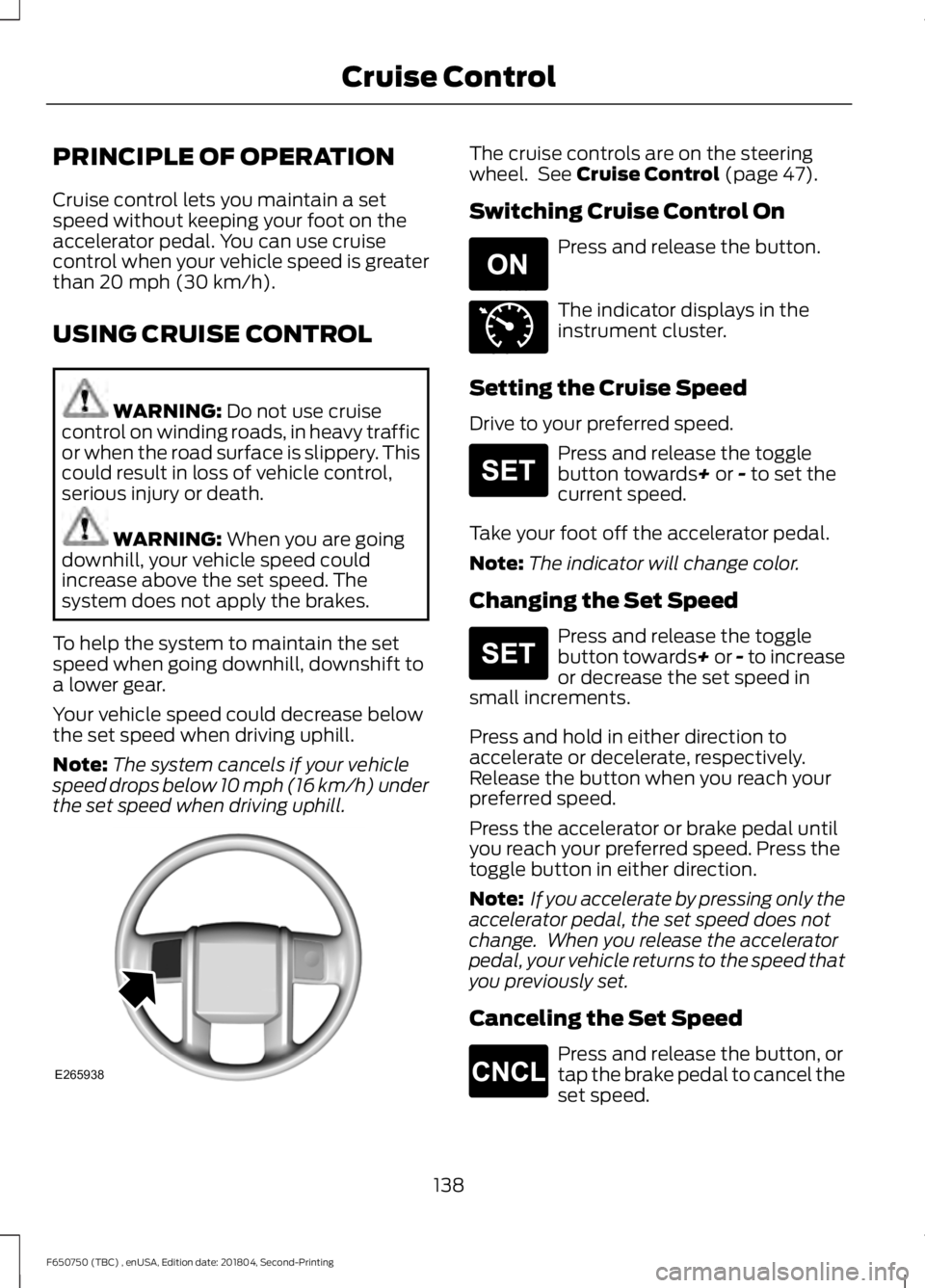
the set speed when driving uphill. The cruise controls are on the steering
wheel. See
Cruise Control (page 47).
Switching Cruise Control On Press and release the button.
The indicator displays in the
instrument cluster.
Setting the Cruise Speed
Drive to your preferred speed. Press and release the toggle
button towards
+ or - to set the
current speed.
Take your foot off the accelerator pedal.
Note: The indicator will change color.
Changing the Set Speed Press and release the toggle
button towards+ or - to increase
or decrease the set speed in
small increments.
Press and hold in either direction to
accelerate or decelerate, respectively.
Release the button when you reach your
preferred speed.
Press the accelerator or brake pedal until
you reach your preferred speed. Press the
toggle button in either direction.
Note: If you accelerate by pressing only the
accelerator pedal, the set speed does not
change. When you release the accelerator
pedal, your vehicle returns to the speed that
you previously set.
Canceling the Set Speed Press and release the button, or
tap the brake pedal to cancel the
set speed.
138
F650750 (TBC) , enUSA, Edition date: 201804, Second-Printing Cruise ControlE265938 E265296 E71340 E265306 E265306 E265298