2019 FORD F650/750 warning
[x] Cancel search: warningPage 158 of 387
Vehicles Sold in Canada: Getting
Roadside Assistance
To fully assist you should you have a
vehicle concern, Ford Motor Company of
Canada, Limited offers a complimentary
roadside assistance program. This program
is eligible within Canada or the continental
United States.
The service is available 24 hours a day,
seven days a week.
This program is separate from the New
Vehicle Limited Warranty, but the coverage
is concurrent with the powertrain coverage
period of your vehicle. Canadian roadside
coverage and benefits may differ from the
U.S. coverage.
If you require more information, please call
us in Canada at 1-800-665-2006, or visit
our website at www.ford.ca.
HAZARD FLASHERS
Note:
If used when the vehicle is not
running, the battery loses charge. As a result,
there may be insufficient power to restart
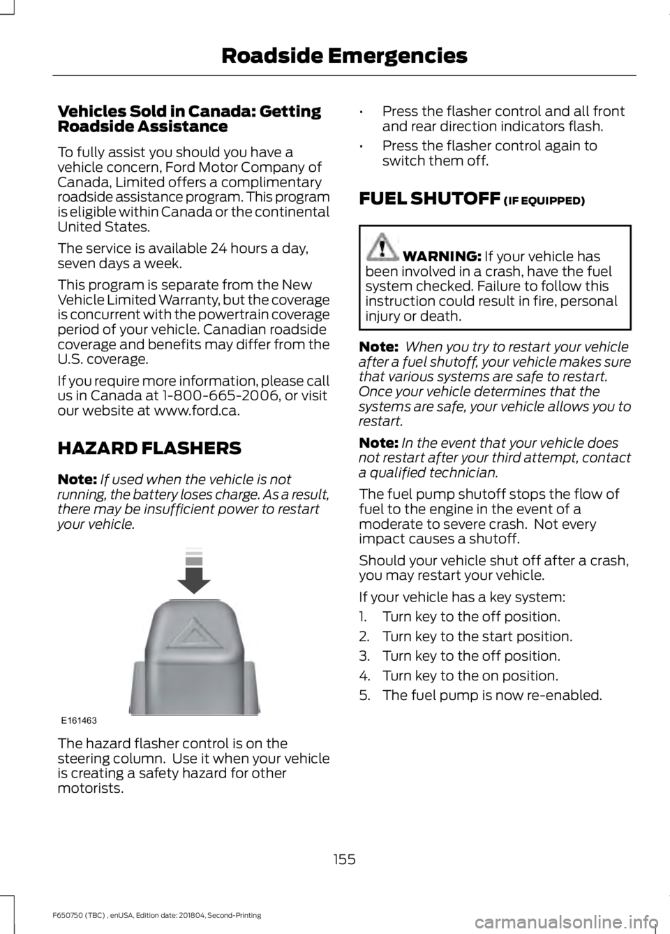
your vehicle. The hazard flasher control is on the
steering column. Use it when your vehicle
is creating a safety hazard for other
motorists. •
Press the flasher control and all front
and rear direction indicators flash.
• Press the flasher control again to
switch them off.
FUEL SHUTOFF (IF EQUIPPED) WARNING:
If your vehicle has
been involved in a crash, have the fuel
system checked. Failure to follow this
instruction could result in fire, personal
injury or death.
Note: When you try to restart your vehicle
after a fuel shutoff, your vehicle makes sure
that various systems are safe to restart.
Once your vehicle determines that the
systems are safe, your vehicle allows you to
restart.
Note: In the event that your vehicle does
not restart after your third attempt, contact
a qualified technician.
The fuel pump shutoff stops the flow of
fuel to the engine in the event of a
moderate to severe crash. Not every
impact causes a shutoff.
Should your vehicle shut off after a crash,
you may restart your vehicle.
If your vehicle has a key system:
1. Turn key to the off position.
2. Turn key to the start position.
3. Turn key to the off position.
4. Turn key to the on position.
5. The fuel pump is now re-enabled.
155
F650750 (TBC) , enUSA, Edition date: 201804, Second-Printing Roadside EmergenciesE161463
Page 159 of 387
JUMP STARTING THE VEHICLE
WARNING: Batteries normally
produce explosive gases which can
cause personal injury. Therefore, do not
allow flames, sparks or lighted
substances to come near the battery.
When working near the battery, always
shield your face and protect your eyes.
Always provide correct ventilation. WARNING:
Keep batteries out of
reach of children. Batteries contain
sulfuric acid. Avoid contact with skin,
eyes or clothing. Shield your eyes when
working near the battery to protect
against possible splashing of acid
solution. In case of acid contact with skin
or eyes, flush immediately with water for
a minimum of 15 minutes and get prompt
medical attention. If acid is swallowed,
call a physician immediately. WARNING:
Use only adequately
sized cables with insulated clamps.
Preparing Your Vehicle
Do not attempt to push-start your
automatic transmission vehicle.
Note: Attempting to push-start a vehicle
with an automatic transmission may cause
transmission damage.
Note: Use only a 12-volt supply to start your
vehicle.
Note: Do not disconnect the battery of the
disabled vehicle as this could damage the
vehicle electrical system.
Park the booster vehicle close to the hood
of the disabled vehicle, making sure the
two vehicles do not touch. Connecting the Jumper Cables WARNING:
Do not attach the
cables to fuel lines, engine rocker covers,
the intake manifold or electrical
components as grounding points. Stay
clear of moving parts. To avoid reverse
polarity connections, make sure that you
correctly identify the positive (+) and
negative (-) terminals on both the
disabled and booster vehicles before
connecting the cables. WARNING:
Do not attach the end
of the positive cable to the studs or
L-shaped eyelet located above the
positive (+) terminal of your vehicle ’s
battery. High current may flow through
and cause damage to the fuses. WARNING:
Do not connect the
end of the second cable to the negative
(-) terminal of the battery to be jumped.
A spark may cause an explosion of the
gases that surround the battery.
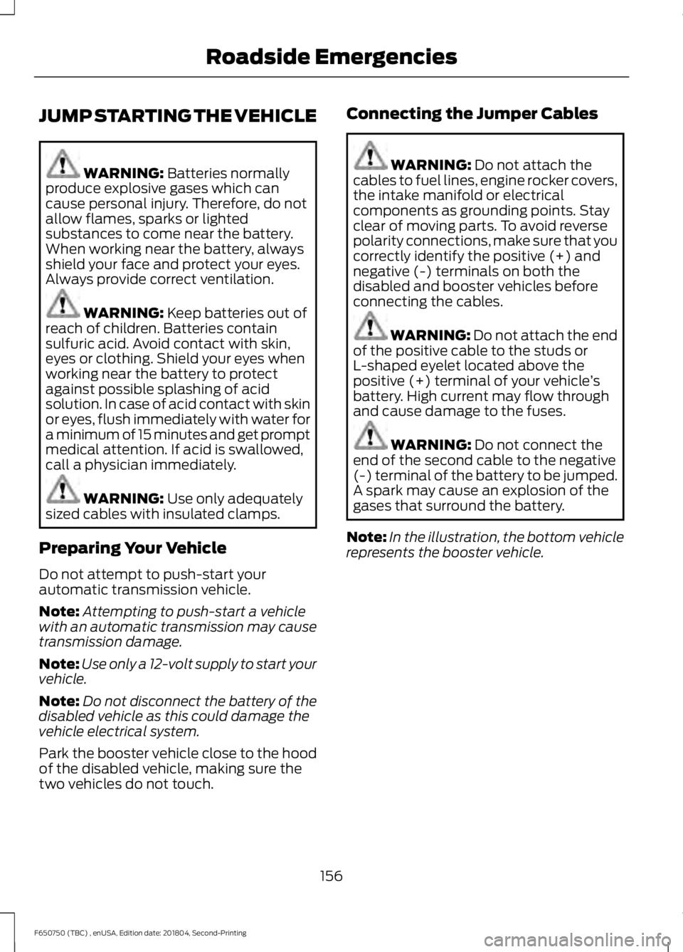
Note: In the illustration, the bottom vehicle
represents the booster vehicle.
156
F650750 (TBC) , enUSA, Edition date: 201804, Second-Printing Roadside Emergencies
Page 161 of 387
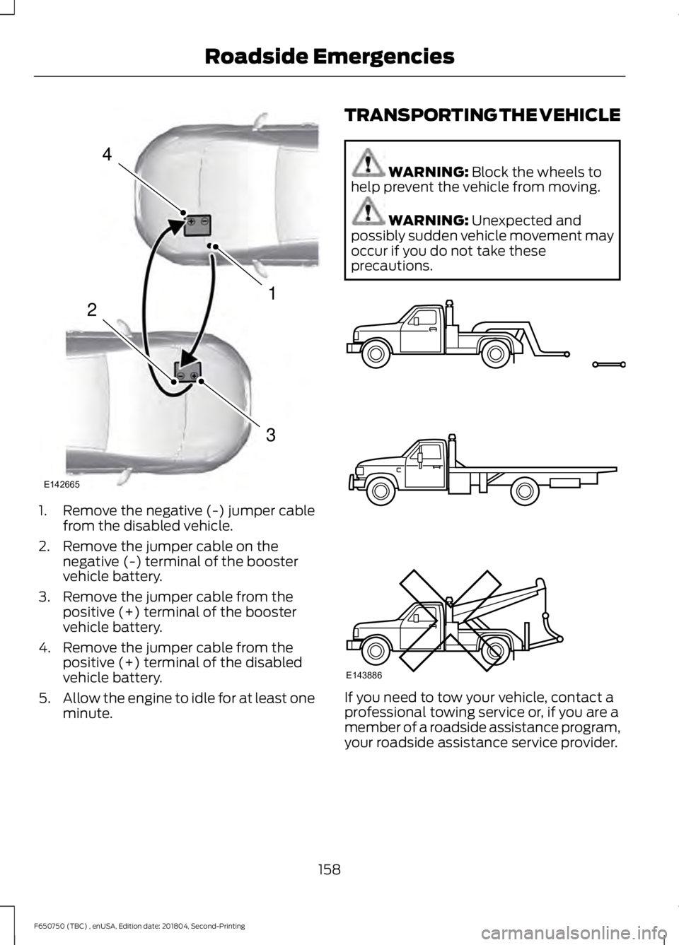
1. Remove the negative (-) jumper cable
from the disabled vehicle.
2. Remove the jumper cable on the negative (-) terminal of the booster
vehicle battery.
3. Remove the jumper cable from the positive (+) terminal of the booster
vehicle battery.
4. Remove the jumper cable from the positive (+) terminal of the disabled
vehicle battery.
5. Allow the engine to idle for at least one
minute. TRANSPORTING THE VEHICLE WARNING: Block the wheels to
help prevent the vehicle from moving. WARNING:
Unexpected and
possibly sudden vehicle movement may
occur if you do not take these
precautions. If you need to tow your vehicle, contact a
professional towing service or, if you are a
member of a roadside assistance program,
your roadside assistance service provider.
158
F650750 (TBC) , enUSA, Edition date: 201804, Second-Printing Roadside Emergencies4
1
3
2
E142665 E143886
Page 170 of 387

FUSE SPECIFICATION CHART
Power Distribution Box
WARNING: Always disconnect the
battery before servicing high current
fuses. WARNING: To reduce risk of
electrical shock, always replace the
cover to the power distribution box
before reconnecting the battery or
refilling fluid reservoirs. The power distribution box is in the engine
compartment. It has high-current fuses
that protect your vehicle's main electrical
systems from overloads.
If you disconnect and reconnect the
battery, you will need to reset some
features. See Changing the 12V Battery
(page
208). Protected Component
Fuse Rating
Fuse or Relay
Number
Blower motor.
Relay
1
Trailer tow and body builder stop lamps.
Relay
2
Urea heaters (diesel engine).
Relay
3
Driver air ride seat compressor.
Relay
4
Heated mirrors.
Relay
5
Not used.
—
6
Not used.
—
7
Passenger air ride seat compressor.
20A 1
8
167
F650750 (TBC) , enUSA, Edition date: 201804, Second-Printing FusesE163101
Page 179 of 387
CHANGING A FUSE
Fuses
WARNING: Always replace a fuse
with one that has the specified
amperage rating. Using a fuse with a
higher amperage rating can cause severe
wire damage and could start a fire. If electrical components in the vehicle are
not working, a fuse may have blown. Blown
fuses are identified by a broken wire within
the fuse. Check the appropriate fuses
before replacing any electrical
components.
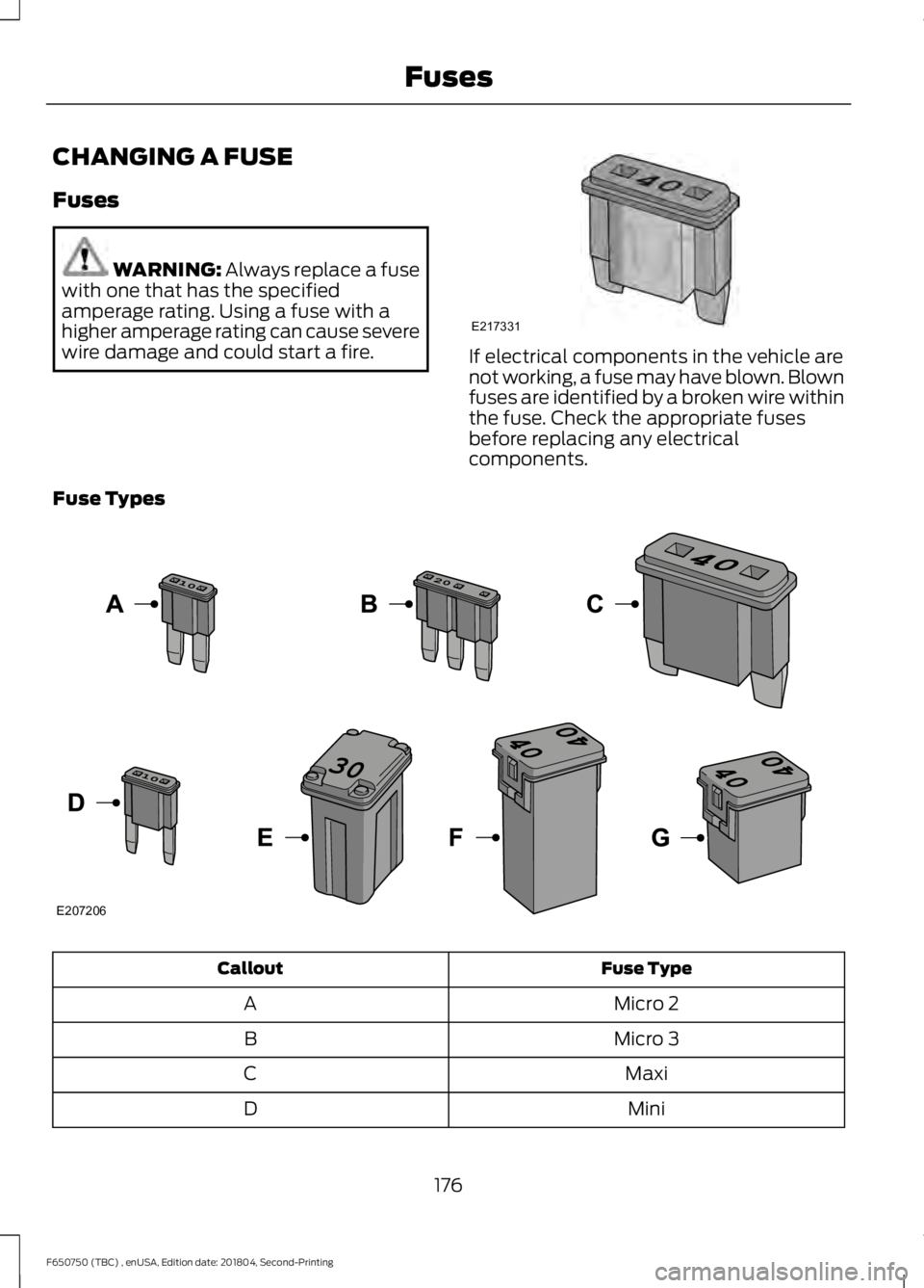
Fuse Types Fuse Type
Callout
Micro 2
A
Micro 3
B
Maxi
C
Mini
D
176
F650750 (TBC) , enUSA, Edition date: 201804, Second-Printing FusesE217331 E207206
Page 181 of 387
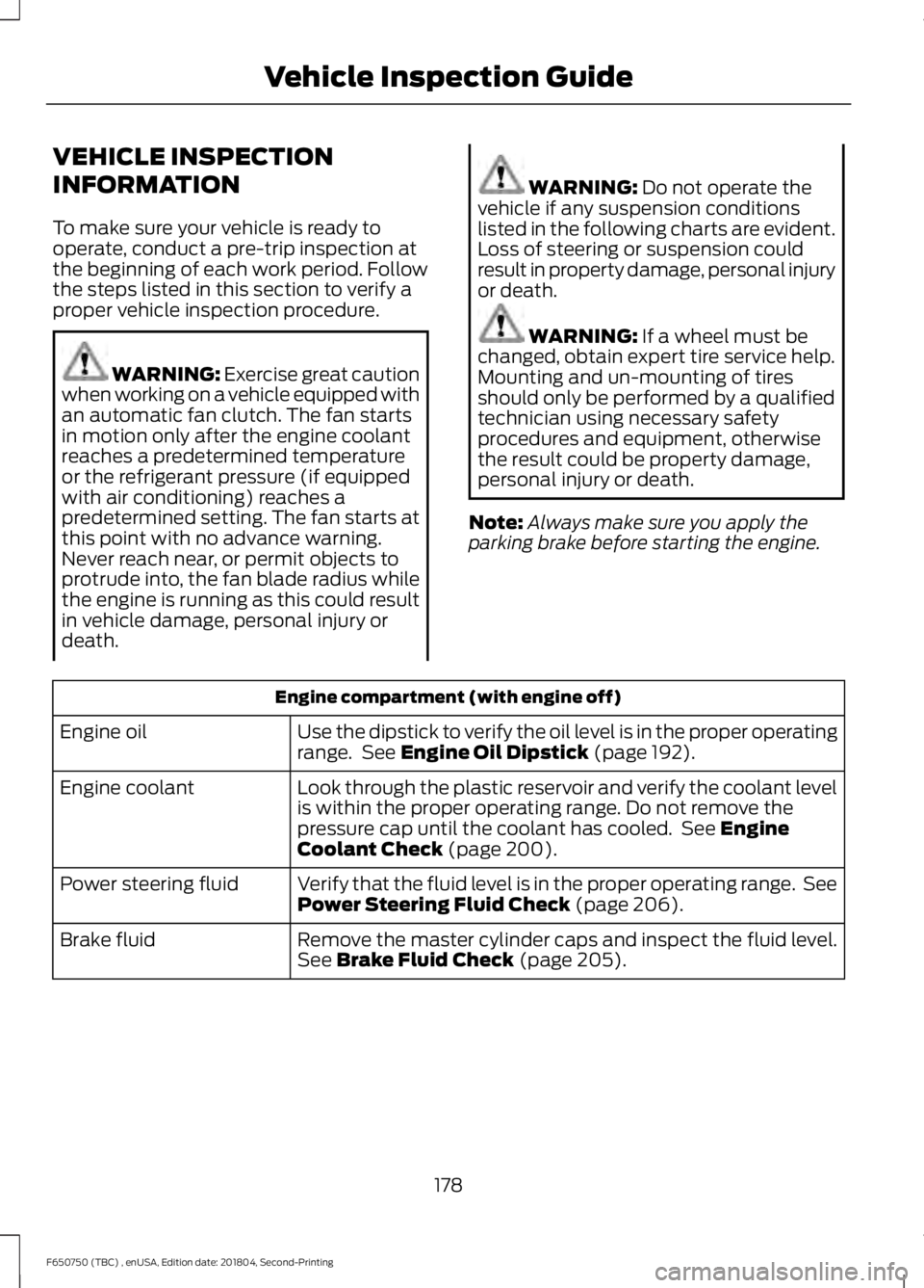
VEHICLE INSPECTION
INFORMATION
To make sure your vehicle is ready to
operate, conduct a pre-trip inspection at
the beginning of each work period. Follow
the steps listed in this section to verify a
proper vehicle inspection procedure.
WARNING: Exercise great caution
when working on a vehicle equipped with
an automatic fan clutch. The fan starts
in motion only after the engine coolant
reaches a predetermined temperature
or the refrigerant pressure (if equipped
with air conditioning) reaches a
predetermined setting. The fan starts at
this point with no advance warning.
Never reach near, or permit objects to
protrude into, the fan blade radius while
the engine is running as this could result
in vehicle damage, personal injury or
death. WARNING:
Do not operate the
vehicle if any suspension conditions
listed in the following charts are evident.
Loss of steering or suspension could
result in property damage, personal injury
or death. WARNING:
If a wheel must be
changed, obtain expert tire service help.
Mounting and un-mounting of tires
should only be performed by a qualified
technician using necessary safety
procedures and equipment, otherwise
the result could be property damage,
personal injury or death.
Note: Always make sure you apply the
parking brake before starting the engine. Engine compartment (with engine off)
Use the dipstick to verify the oil level is in the proper operating
range. See
Engine Oil Dipstick (page 192).
Engine oil
Look through the plastic reservoir and verify the coolant level
is within the proper operating range. Do not remove the
pressure cap until the coolant has cooled. See
Engine
Coolant Check (page 200).
Engine coolant
Verify that the fluid level is in the proper operating range. See
Power Steering Fluid Check
(page 206).
Power steering fluid
Remove the master cylinder caps and inspect the fluid level.
See
Brake Fluid Check (page 205).
Brake fluid
178
F650750 (TBC) , enUSA, Edition date: 201804, Second-Printing Vehicle Inspection Guide
Page 182 of 387

Engine compartment (with engine off)
Inspect for glazing, fraying or cracking. There should be no
more than 5-7 cracks per rib, per 1 in (2.5 cm)
Belts (fan, alternator,
water pump and air
conditioning
compressor)
Inspect for signs of fluid puddles or dripping fluid on the
ground under the engine, or the underside of the engine.
Fluid leaks
Inspect for debris that may have collected on the HVAC air
inlet grille or inside the exterior module as this may reduce
system performance.
HVAC air inlet Engine starting (with parking brake applied)
Before entering the cab, verify that the vehicle is equipped
with spare electrical fuses (if used), three red reflective
triangles, a properly charged and rated fire extinguisher and
wheel chocks.
Safety and emergency
equipment
Walk around the vehicle and verify all steps and grab handles,
inside and out (as well as behind), are tight and clean. Use
extreme caution and a three-point stance at all times.
Inspect door latches for proper closing, latching and locking.
Set the parking brake. Make sure the gearshift lever is in
neutral (N) or park (P) (if equipped with a park position).
Starting the engine
Diesel engine:
Turn the key to the on position. Turn the key
to start when the wait to start indicator light in the instrument
cluster turns off.
Gasoline engine:
Turn the key to start, and then release it
as soon as the engine starts.
Verify pressure builds to normal operating range.
Engine oil pressure
A tone indicating low air pressure should sound immediately
after the engine starts but before the compressor has built-
up pressure. The tone should stop when the air pressure
reaches
70 psi (483 kPa). Let the air pressure build to
governed cutout pressure, which should occur between
115– 130 psi (793–896 kPa)
.
Low air pressure warning
tone (if equipped with an
air compressor)
Press the accelerator and verify that it operates smoothly,
without any binding or irregular feel. Release the pedal and
verify the engine returns to idle speed immediately.
Accelerator
179
F650750 (TBC) , enUSA, Edition date: 201804, Second-Printing Vehicle Inspection Guide
Page 183 of 387
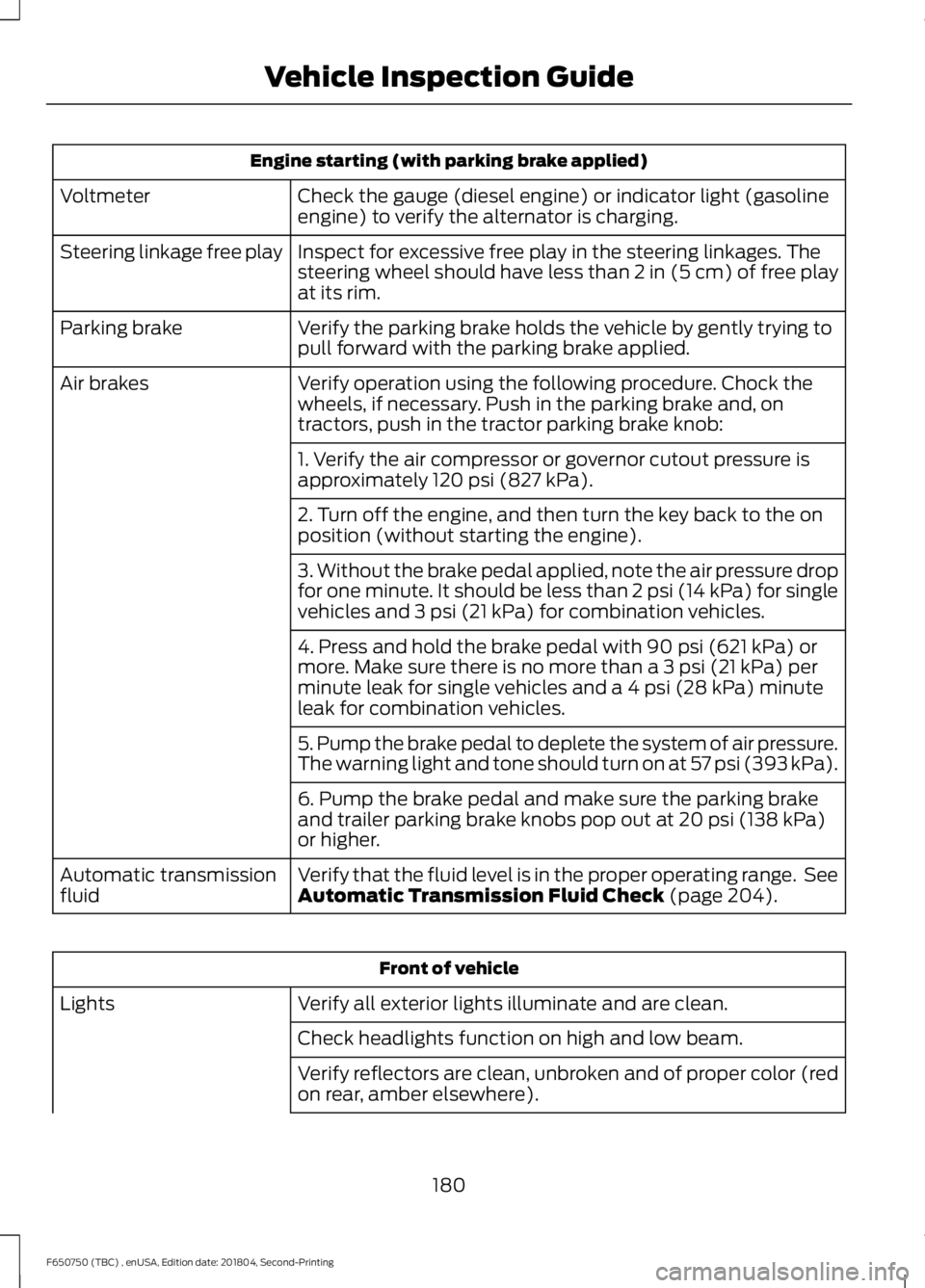
Engine starting (with parking brake applied)
Check the gauge (diesel engine) or indicator light (gasoline
engine) to verify the alternator is charging.
Voltmeter
Inspect for excessive free play in the steering linkages. The
steering wheel should have less than 2 in (5 cm) of free play
at its rim.
Steering linkage free play
Verify the parking brake holds the vehicle by gently trying to
pull forward with the parking brake applied.
Parking brake
Verify operation using the following procedure. Chock the
wheels, if necessary. Push in the parking brake and, on
tractors, push in the tractor parking brake knob:
Air brakes
1. Verify the air compressor or governor cutout pressure is
approximately 120 psi (827 kPa).
2. Turn off the engine, and then turn the key back to the on
position (without starting the engine).
3. Without the brake pedal applied, note the air pressure drop
for one minute. It should be less than 2 psi (14 kPa) for single
vehicles and
3 psi (21 kPa) for combination vehicles.
4. Press and hold the brake pedal with
90 psi (621 kPa) or
more. Make sure there is no more than a 3 psi (21 kPa) per
minute leak for single vehicles and a 4 psi (28 kPa) minute
leak for combination vehicles.
5. Pump the brake pedal to deplete the system of air pressure.
The warning light and tone should turn on at 57 psi (393 kPa).
6. Pump the brake pedal and make sure the parking brake
and trailer parking brake knobs pop out at
20 psi (138 kPa)
or higher.
Verify that the fluid level is in the proper operating range. See
Automatic Transmission Fluid Check
(page 204).
Automatic transmission
fluid Front of vehicle
Verify all exterior lights illuminate and are clean.
Lights
Check headlights function on high and low beam.
Verify reflectors are clean, unbroken and of proper color (red
on rear, amber elsewhere).
180
F650750 (TBC) , enUSA, Edition date: 201804, Second-Printing Vehicle Inspection Guide