2019 FORD F650/750 tire type
[x] Cancel search: tire typePage 124 of 387
WARNING: Sudden accelerations
on slippery surfaces could cause the
wheels to spin, the vehicle to turn
sideways on a crowned road surface or
in a turn, possibly resulting in loss of
vehicle control and personal injury.
Activating the Locking Differential
You can lock and unlock the differential
when your vehicle is moving at a constant
speed of less than 25 mph (40 km/h) and
while the wheels are not slipping. Do not
lock the differential when your vehicle is
traveling down steep grades and when
traction is minimal.
The differential lock and differential lock
light automatically disengage at speeds
above 25 mph (40 km/h). The differential
lock remains off until either you restart your
vehicle or you turn the differential lock
switch off then back on.
Servicing a Vehicle with a Locking
Differential
Turn the engine off and raise all drive
wheels of the locker differential axle in
order to prevent your vehicle from moving
when servicing the wheels, tires or brakes.
Axles equipped with a driver-controlled
differential deliver power to both wheels
even when only one wheel is on the ground. WARNING: Failure to raise all drive
wheels with this type of differential could
cause the vehicle to move unexpectedly,
resulting in property damage, personal
injury or death. 2-SPEED REAR AXLE (IF EQUIPPED) WARNING:
Never shift a
two-speed axle when descending a
steep grade as this may cause loss of
vehicle control and result in personal
injury.
Note: Do not shift between ranges when
the speed control is on.
A two-speed rear axle allows the driver to
select a low range for greater pulling power
and a high range for greater road speed
and fuel economy. You can also use these
ranges to provide extra steps between
transmission shifts when driving on steep
grades or fuel economy may be factors.
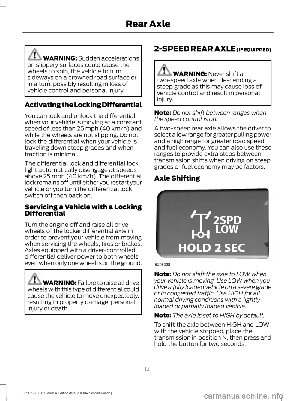
Axle Shifting Note:
Do not shift the axle to LOW when
your vehicle is moving. Use LOW when you
drive a fully loaded vehicle on a severe grade
or in congested traffic. Use HIGH for all
normal driving conditions with a lightly
loaded or partially loaded vehicle.
Note: The axle is set to HIGH by default.
To shift the axle between HIGH and LOW
with the vehicle stopped, place the
transmission in position N, then press and
hold the button for two seconds.
121
F650750 (TBC) , enUSA, Edition date: 201804, Second-Printing Rear AxleE208228
Page 149 of 387
ESSENTIAL TOWING CHECKS
See Load limits in the Load Carrying
chapter for load specification terms found
on the tire label and Safety Compliance
label and instructions on calculating your
vehicle's load.
Remember to account for the trailer
tongue weight as part of your vehicle load
when calculating the total vehicle weight.
Hitches
Do not use a hitch that either clamps onto
the bumper or attaches to the axle. You
must distribute the load in your trailer so
that 10-15% of the total weight of the
trailer is on the tongue.
Safety Chains
Note: Do not attach safety chains to the
bumper.
Always connect the safety chains to the
frame or hook retainers of your vehicle
hitch.
To connect the safety chains, cross the
chains under the trailer tongue and allow
enough slack for turning tight corners. Do
not allow the chains to drag on the ground.
Trailer Brakes WARNING:
Do not connect a
trailer's hydraulic brake system directly
to your vehicle's brake system. Your
vehicle may not have enough braking
power and your chances of having a
collision greatly increase.
Electric brakes and manual, automatic or
surge-type trailer brakes are safe if you
install them properly and adjust them to
the manufacturer's specifications. The
trailer brakes must meet local and federal
regulations. The rating for the tow vehicle's braking
system operation is at the gross vehicle
weight rating, not the gross combined
weight rating.
Trailer Lamps
WARNING:
Never connect any
trailer lamp wiring to the vehicle's tail
lamp wiring; this may damage the
electrical system resulting in fire. Contact
your authorized dealer as soon as
possible for assistance in proper trailer
tow wiring installation. Additional
electrical equipment may be required.
Trailer lamps are required on most towed
vehicles. Make sure all running lights, brake
lights, turn signals and hazard lights are
working.
Before Towing a Trailer
Practice turning, stopping and backing up
to get the feel of your vehicle-trailer
combination before starting on a trip.
When turning, make wider turns so the
trailer wheels clear curbs and other
obstacles.
When Towing a Trailer
• Check your hitch, electrical connections
and trailer wheel lug nuts thoroughly
after you have traveled
50 mph
(80 km/h).
• When stopped in congested or heavy
traffic during hot weather, place the
transmission in park (P) or neutral (N)
to aid engine and transmission cooling
and to help air conditioning
performance.
• Turn off the speed control with heavy
loads or in hilly terrain. The speed
control may turn off automatically
when you are towing on long, steep
grades.
146
F650750 (TBC) , enUSA, Edition date: 201804, Second-Printing Towing
Page 227 of 387
Once a year, inspect the entire brake
system:
•
Rubber components for deterioration.
A qualified technician should inspect
these components and replace them
as necessary. Replacement intervals
vary according to the severity and
length of vehicle service.
• Condition of brake drums, brake
chambers and slack adjusters.
• System for air leaks.
• Hose or pipes for rust, damage and
deterioration.
• Operation of service and parking
brakes.
Periodically inspect parts such as air brake
chamber diaphragm, air compressor and
air cleaner. Replace any parts if you can
consider them unserviceable.
Air Dryer
Climactic conditions affect performance
of desiccant or after-cooler type air dryers.
You must establish a maintenance
schedule for each specific operation.
The use of an air dryer on a vehicle does
not eliminate the need to drain the air
reservoirs periodically.
Inspect for moisture in the air system by
opening reservoirs, draincocks or valves
and checking for presence of water. The
presence of small amounts of water due
to condensation is normal and is not an
indication that the dryer is not functioning
properly. Replace or rebuild the desiccant cartridge
when you determine that the desiccant is
contaminated and does not have adequate
water absorption capacity. The desiccant
change interval may vary. A general
recommendation is to replace the
desiccant every 12 months (yearly). If
experience has shown that extended or
shortened life has resulted for a particular
installation, then the yearly interval can be
increased or decreased accordingly.
Draining the Air Brake Reservoir
WARNING: Failure to drain air
brake reservoirs can result in a reduction
or loss of braking ability due to fluid
accumulation in the reservoir and/or
possible freeze-up during cold weather.
Completely drain all the air brake reservoirs
daily by opening the draincock at the ends
of the tanks. (Where accessible.
Pull-chains are used when the drains are
undercab or otherwise inaccessible.) Close
the draincock after draining. Manually drain
any air tanks equipped with automatic
moisture ejector valves, as required, to
maintain a dry air system. Contact an
authorized dealer if you are unsure of the
air reservoir locations or the draining
procedure.
Hydraulic Brakes
Establish a regular schedule for periodic
cleaning, lubrication and adjustment
inspection based on vehicle use. Exact
maintenance intervals are difficult to
predetermine due to vehicle applications
and operating conditions. If you are
uncertain of the proper schedule for your
vehicle, contact an authorized dealer.
224
F650750 (TBC) , enUSA, Edition date: 201804, Second-Printing Maintenance
Page 229 of 387
Inspecting steer axle tires in the first
3,000–
10,000 mi (5,000– 16,000 km)
generally shows if tires are wearing
normally.
Rapid outside shoulder wear on both tires
indicates too much toe-in.
Rapid inside shoulder wear on both tires
indicates too much toe-out.
In P&D-type service, there can be a
left-to-right steer tire tread life differential
up to 40% depending on routes and other
variables.
Follow the tire manufacturer's
recommended cold inflation pressure for
the tire size, load range (ply rating) and
steer axle loading typical for their operation
(each steer axle tire equals ½ steer axle
loading).
Special applications may warrant a setting
based on experience with the type of tire
operating loads and conditions. Radial tires
are more sensitive to toe-in setting than
bias ply tires. Fine tuning school bus
alignment to line-haul truck standards
does not drastically improve tire tread life.
STEERING SYSTEM
INSPECTION WARNING: Failure to maintain the
steering system in proper condition can
cause reduced steering ability resulting
in property damage, personal injury or
death.
Note: Have any steering problems
immediately corrected by a qualified service
technician.
Ask your service technician to examine the
steering mechanism. Only minor
adjustments may be necessary. Regular inspections should include:
•
Checking the tie rod, drag link end
clamp bolts and ball joints for proper
tightness.
• Checking for installation and spread of
cotter pins and tightness of nuts at
both ends of the tie rod and drag link.
• Checking that the pitman arm (steering
arm at steering gear) mounting is tight
and locked. Check system for leaks or
hose chafing. Repair immediately, if
necessary.
• Maintaining proper steering gear and
power steering pump lubricant levels.
• Checking steering column joint bolts
and steering linkage, particularly for
body-to-chassis clearance.
Steering Column Joint Bolts
As a good maintenance practice, check
steering column joint bolt tightness every
60,000 mi (96,000 km) or annually,
whichever occurs first. Do not overtighten
the bolts.
Hydraulic System
Whenever draining and refilling the power
steering's hydraulic system for any reason,
bleed air from the system before returning
the vehicle to service. Failure to bleed the
hydraulic system properly can result in
degradation of power system performance.
Consult an authorized dealer who is aware
of the proper procedures for filling and
bleeding the system.
226
F650750 (TBC) , enUSA, Edition date: 201804, Second-Printing Maintenance
Page 240 of 387

Information on P Type Tires
P215/65R15 95H is an example of
a tire size, load index and speed
rating. The definitions of these
items are listed below. (Note that
the tire size, load index and speed
rating for your vehicle may be
different from this example.)
A.
P: Indicates a tire, designated
by the Tire and Rim Association,
that may be used for service on
cars, sport utility vehicles,
minivans and light trucks. Note:
If
your tire size does not begin with
a letter this may mean it is
designated by either the European
Tire and Rim Technical
Organization or the Japan Tire
Manufacturing Association. B.
215:
Indicates the nominal
width of the tire in millimeters
from sidewall edge to sidewall
edge. In general, the larger the
number, the wider the tire.
C. 65:
Indicates the aspect ratio
which gives the tire's ratio of
height to width.
D. R:
Indicates a radial type tire.
E. 15:
Indicates the wheel or rim
diameter in inches. If you change
your wheel size, you have to
purchase new tires to match the
new wheel diameter.
F. 95:
Indicates the tire's load
index. It is an index that relates to
how much weight a tire can carry.
Note: You may not find this
information on all tires because it
is not required by federal law.
G. H:
Indicates the tire's speed
rating. The speed rating denotes
the speed at which a tire is
designed to be driven for extended
periods of time under a standard
condition of load and inflation
pressure. The tires on your vehicle
may operate at different
conditions for load and inflation
pressure. These speed ratings may
need to be adjusted for the
difference in conditions. The
ratings range from
81– 186 mph
(130– 299 km/h). These ratings
are listed in the following chart.
Note: You may not find this
information on all tires because it
is not required by federal law.
237
F650750 (TBC) , enUSA, Edition date: 201804, Second-Printing Wheels and TiresH
I
J
KL
M
A
B
CDEFG
E142543
Page 242 of 387
*Traction: The traction grades,
from highest to lowest are AA, A,
B, and C. The grades represent the
tire's ability to stop on wet
pavement as measured under
controlled conditions on specified
government test surfaces of
asphalt and concrete. A tire
marked C may have poor traction
performance.
*
Temperature: The temperature
grades are A (the highest), B and
C, representing the tire's
resistance to the generation of
heat and its ability to dissipate
heat when tested under controlled
conditions on a specified indoor
laboratory test wheel.
M. Maximum Inflation
Pressure:
Indicates the tire
manufacturers' maximum
permissible pressure or the
pressure at which the maximum
load can be carried by the tire. This
pressure is normally higher than
the vehicle manufacturer's
recommended cold inflation
pressure which can be found on
the Safety Compliance
Certification Label. The cold
inflation pressure should never be
set lower than the recommended
pressure on the vehicle label.
The tire suppliers may have
additional markings, notes or
warnings such as standard load
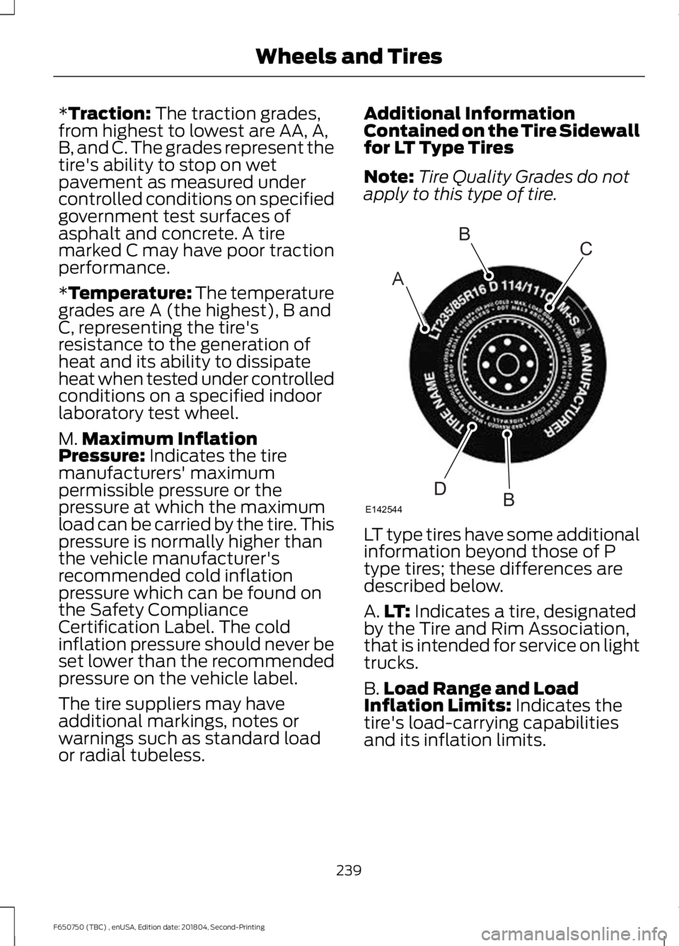
or radial tubeless. Additional Information
Contained on the Tire Sidewall
for LT Type Tires
Note:
Tire Quality Grades do not
apply to this type of tire. LT type tires have some additional
information beyond those of P
type tires; these differences are
described below.
A.
LT:
Indicates a tire, designated
by the Tire and Rim Association,
that is intended for service on light
trucks.
B. Load Range and Load
Inflation Limits:
Indicates the
tire's load-carrying capabilities
and its inflation limits.
239
F650750 (TBC) , enUSA, Edition date: 201804, Second-Printing Wheels and TiresA
BC
BDE142544
Page 243 of 387

C.
Maximum Load Dual lb (kg)
at psi (kPa) cold: Indicates the
maximum load and tire pressure
when the tire is used as a dual;
defined as four tires on the rear
axle (a total of six or more tires on
the vehicle).
D. Maximum Load Single lb
(kg) at psi (kPa) cold:
Indicates
the maximum load and tire
pressure when the tire is used as
a single; defined as two tires
(total) on the rear axle.
Information on T Type Tires
T145/80D16 is an example of a
tire size.
Note: The temporary tire size for
your vehicle may be different from
this example. Tire Quality Grades
do not apply to this type of tire. T type tires have some additional
information beyond those of P
type tires; these differences are
described below:
A.
T:
Indicates a type of tire,
designated by the Tire and Rim
Association, that is intended for
temporary service on cars, sport
utility vehicles, minivans and light
trucks.
B. 145:
Indicates the nominal
width of the tire in millimeters
from sidewall edge to sidewall
edge. In general, the larger the
number, the wider the tire.
240
F650750 (TBC) , enUSA, Edition date: 201804, Second-Printing Wheels and TiresA
BCDE
E142545
Page 244 of 387

C.
80: Indicates the aspect ratio
which gives the tire's ratio of
height to width. Numbers of 70 or
lower indicate a short sidewall.
D. D:
Indicates a diagonal type tire.
R:
Indicates a radial type tire.
E. 16:
Indicates the wheel or rim
diameter in inches. If you change
your wheel size, you have to
purchase new tires to match the
new wheel diameter.
Inflating Your Tires
Safe operation of your vehicle
requires that your tires are
properly inflated. Remember that
a tire can lose up to half of its air
pressure without appearing flat.
Every day before you drive, check
your tires. If one looks lower than
the others, use a tire gauge to
check pressure of all tires and
adjust if required.
At least once a month and before
long trips, inspect each tire and
check the tire pressure with a tire
gauge (including spare, if
equipped). Inflate all tires to the
inflation pressure recommended
by Ford Motor Company.
You are strongly urged to buy a
reliable tire pressure gauge, as
automatic service station gauges
may be inaccurate. Ford
recommends the use of a digital
or dial-type tire pressure gauge
rather than a stick-type tire
pressure gauge. Use the recommended cold
inflation pressure for optimum tire
performance and wear.
Under-inflation or over-inflation
may cause uneven treadwear
patterns
WARNING: Under-inflation
is the most common cause of
tire failures and may result in
severe tire cracking, tread
separation or blowout, with
unexpected loss of vehicle
control and increased risk of
injury. Under-inflation increases
sidewall flexing and rolling
resistance, resulting in heat
buildup and internal damage to
the tire. It also may result in
unnecessary tire stress, irregular
wear, loss of vehicle control and
accidents. A tire can lose up to
half of its air pressure and not
appear to be flat!
Always inflate your tires to the
Ford recommended inflation
pressure even if it is less than the
maximum inflation pressure
information found on the tire. The
Ford recommended tire inflation
pressure is found on the Safety
Compliance Certification Label or
Tire Label. Failure to follow the tire
pressure recommendations can
cause uneven treadwear patterns
and adversely affect the way your
vehicle handles.
241
F650750 (TBC) , enUSA, Edition date: 201804, Second-Printing Wheels and Tires