Page 413 of 666
4. Loosen each wheel lug nut ½ turn
counterclockwise, but do not remove
them until the wheel is raised off the
ground.
Note: For vehicles with dual rear wheels,
insert the lug wrench extension into the lug
wrench to reach the lug nuts.
F-250 and F-350 Single Rear Wheel
Vehicles 1. Insert the hooked end of the jack
handle into the jack and turn the
handle clockwise until the wheel is
completely off the ground and high
enough to install the spare tire.
2. Position the jack according to the following guides: Front (4x2) Front driver side (4x4)
Note:
Make sure the jack fits onto the flat
area on the outboard side of the differential. Front passenger side (4x4)
Note:
View shown from the rear of the
vehicle to clearly identify the jack point.
Place the jack directly under the axle. 410
Super Duty (TFE) Canada/United States of America, enUSA, Edition date: 201804, Fourth-Printing Wheels and TiresE162801 E162802 E162803 E162804 E162805
Page 414 of 666
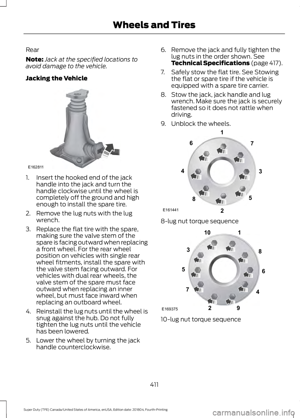
Rear
Note:
Jack at the specified locations to
avoid damage to the vehicle.
Jacking the Vehicle 1. Insert the hooked end of the jack
handle into the jack and turn the
handle clockwise until the wheel is
completely off the ground and high
enough to install the spare tire.
2. Remove the lug nuts with the lug wrench.
3. Replace the flat tire with the spare, making sure the valve stem of the
spare is facing outward when replacing
a front wheel. For the rear wheel
position on vehicles with single rear
wheel fitments, install the spare with
the valve stem facing outward. For
vehicles with dual rear wheels, the
valve stem of the spare must face
outward when replacing an inner
wheel, but must face inward when
replacing an outboard wheel.
4. Reinstall the lug nuts until the wheel is
snug against the hub. Do not fully
tighten the lug nuts until the vehicle
has been lowered.
5. Lower the wheel by turning the jack handle counterclockwise. 6. Remove the jack and fully tighten the
lug nuts in the order shown. See
Technical Specifications (page 417).
7. Safely stow the flat tire. See Stowing the flat or spare tire if the vehicle is
equipped with a spare tire carrier.
8. Stow the jack, jack handle and lug wrench. Make sure the jack is securely
fastened so it does not rattle when
driving.
9. Unblock the wheels. 8-lug nut torque sequence
10-lug nut torque sequence
411
Super Duty (TFE) Canada/United States of America, enUSA, Edition date: 201804, Fourth-Printing Wheels and TiresE162811 E161441
13
4
27
6
5
8 1
2
3
4
5
6
7 8
9
10
E169375
Page 415 of 666
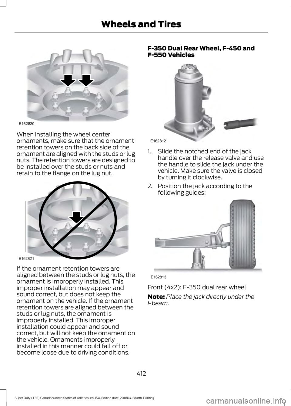
When installing the wheel center
ornaments, make sure that the ornament
retention towers on the back side of the
ornament are aligned with the studs or lug
nuts. The retention towers are designed to
be installed over the studs or nuts and
retain to the flange on the lug nut.
If the ornament retention towers are
aligned between the studs or lug nuts, the
ornament is improperly installed. This
improper installation may appear and
sound correct, but does not keep the
ornament on the vehicle. If the ornament
retention towers are aligned between the
studs or lug nuts, the ornament is
improperly installed. This improper
installation could appear and sound
correct, but will not keep the ornament on
the vehicle. Ornaments improperly
installed in this manner could fall off or
become loose due to driving conditions. F-350 Dual Rear Wheel, F-450 and
F-550 Vehicles
1. Slide the notched end of the jack
handle over the release valve and use
the handle to slide the jack under the
vehicle. Make sure the valve is closed
by turning it clockwise.
2. Position the jack according to the following guides: Front (4x2): F-350 dual rear wheel
Note:
Place the jack directly under the
I-beam.
412
Super Duty (TFE) Canada/United States of America, enUSA, Edition date: 201804, Fourth-Printing Wheels and TiresE162820 E162821 E162812 E162813
Page 417 of 666

Jacking the Vehicle
1. Insert the jack handle into the pump
linkage.
2. Use an up-and-down motion with the jack handle to raise the wheel
completely off the ground.
Note: Hydraulic jacks are equipped with a
pressure relief valve that prevents lifting
loads which exceed the jack's rated
capacity.
3. Remove the lug nuts with the lug wrench.
4. Replace the flat tire with the spare, making sure the valve stem of the
spare is facing outward when replacing
a front wheel. For the rear wheel
positions, the valve stem of the spare
must face outward when replacing an
inner wheel, but must face inward
when replacing an outboard wheel.
5. Reinstall the lug nuts until the wheel is
snug against the hub. Do not fully
tighten the lug nuts until the vehicle
has been lowered.
6. Lower the wheel by slowly turning the release valve counterclockwise.
Opening the release valve slowly
provides a more controlled rate of
descent. 7. Remove the jack and fully tighten the
lug nuts in the order shown. See
Technical Specifications (page 417).
8. Stow the flat tire. See Stowing the flat or spare tire if the vehicle is equipped
with a spare tire carrier.
9. Stow the jack, jack handle and lug wrench. Make sure the jack is securely
fastened so it does not rattle when
driving.
10. Unblock the wheels. 8-lug nut torque sequence
10-lug nut torque sequence
414
Super Duty (TFE) Canada/United States of America, enUSA, Edition date: 201804, Fourth-Printing Wheels and TiresE162819 E161441
13
4
27
6
5
8 1
2
3
4
5
6
7 8
9
10
E169375
Page 419 of 666
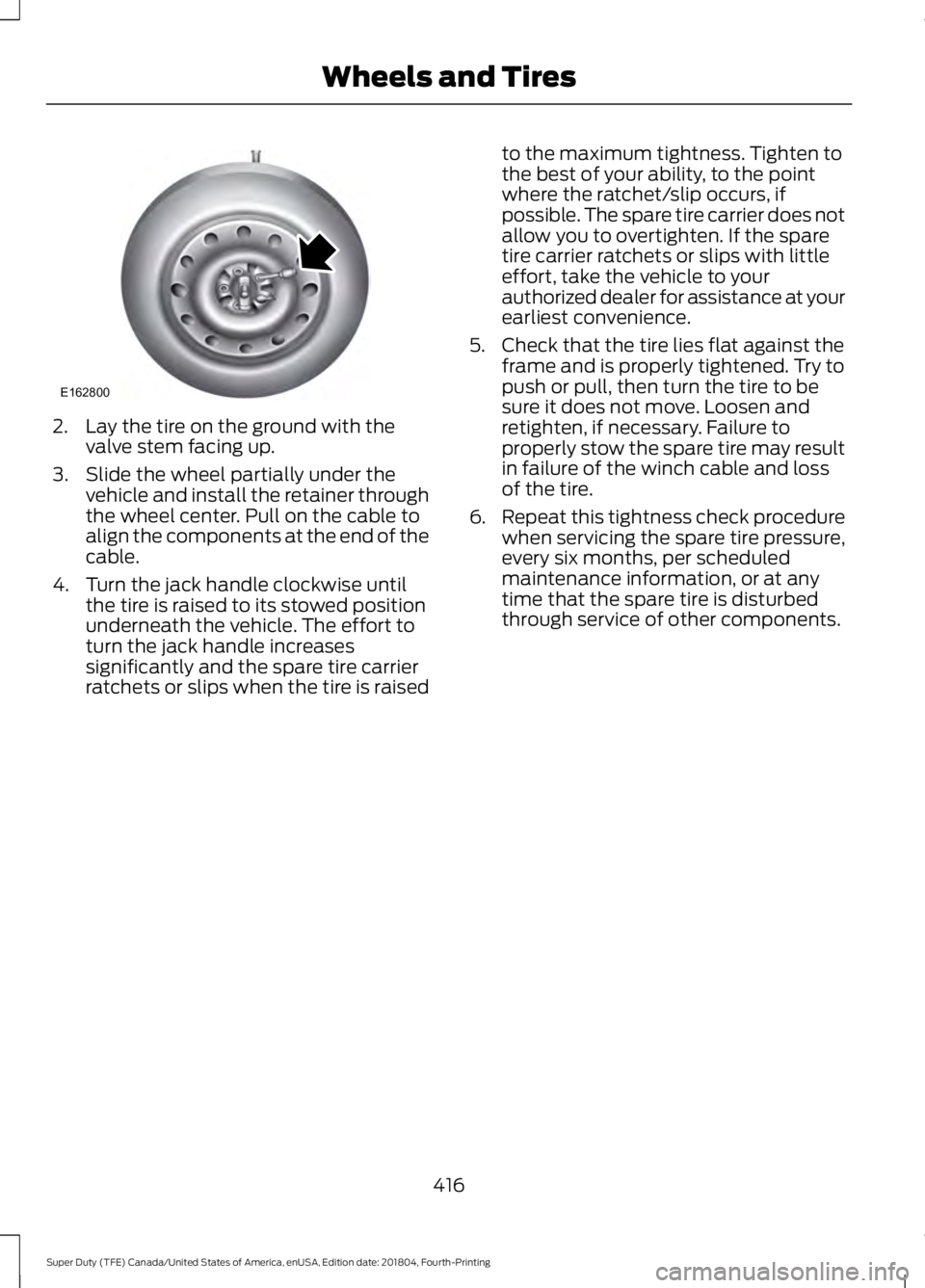
2. Lay the tire on the ground with the
valve stem facing up.
3. Slide the wheel partially under the vehicle and install the retainer through
the wheel center. Pull on the cable to
align the components at the end of the
cable.
4. Turn the jack handle clockwise until the tire is raised to its stowed position
underneath the vehicle. The effort to
turn the jack handle increases
significantly and the spare tire carrier
ratchets or slips when the tire is raised to the maximum tightness. Tighten to
the best of your ability, to the point
where the ratchet/slip occurs, if
possible. The spare tire carrier does not
allow you to overtighten. If the spare
tire carrier ratchets or slips with little
effort, take the vehicle to your
authorized dealer for assistance at your
earliest convenience.
5. Check that the tire lies flat against the frame and is properly tightened. Try to
push or pull, then turn the tire to be
sure it does not move. Loosen and
retighten, if necessary. Failure to
properly stow the spare tire may result
in failure of the winch cable and loss
of the tire.
6. Repeat this tightness check procedure
when servicing the spare tire pressure,
every six months, per scheduled
maintenance information, or at any
time that the spare tire is disturbed
through service of other components.
416
Super Duty (TFE) Canada/United States of America, enUSA, Edition date: 201804, Fourth-Printing Wheels and TiresE162800
Page 429 of 666
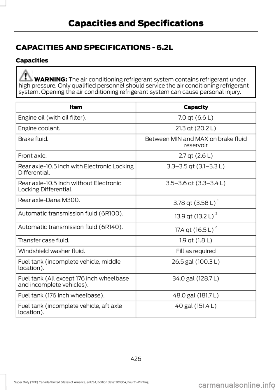
CAPACITIES AND SPECIFICATIONS - 6.2L
Capacities
WARNING: The air conditioning refrigerant system contains refrigerant under
high pressure. Only qualified personnel should service the air conditioning refrigerant
system. Opening the air conditioning refrigerant system can cause personal injury. Capacity
Item
7.0 qt (6.6 L)
Engine oil (with oil filter).
21.3 qt (20.2 L)
Engine coolant.
Between MIN and MAX on brake fluidreservoir
Brake fluid.
2.7 qt (2.6 L)
Front axle.
3.3–3.5 qt (3.1– 3.3 L)
Rear axle-10.5 inch with Electronic Locking
Differential.
3.5–3.6 qt (3.3– 3.4 L)
Rear axle-10.5 inch without Electronic
Locking Differential.
3.78 qt (3.58 L)1
Rear axle-Dana M300.
13.9 qt (13.2 L)2
Automatic transmission fluid (6R100).
17.4 qt (16.5 L)2
Automatic transmission fluid (6R140).
1.9 qt (1.8 L)
Transfer case fluid.
Fill as required
Windshield washer fluid.
26.5 gal (100.3 L)
Fuel tank (incomplete vehicle, middle
location).
34.0 gal (128.7 L)
Fuel tank (All except 176 inch wheelbase
and incomplete vehicles).
48.0 gal (181.7 L)
Fuel tank (176 inch wheelbase).
40 gal (151.4 L)
Fuel tank (incomplete vehicle, aft axle
location).
426
Super Duty (TFE) Canada/United States of America, enUSA, Edition date: 201804, Fourth-Printing Capacities and Specifications
Page 430 of 666
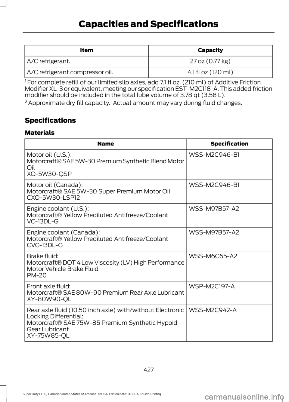
Capacity
Item
27 oz (0.77 kg)
A/C refrigerant.
4.1 fl oz (120 ml)
A/C refrigerant compressor oil.
1 For complete refill of our limited slip axles, add 7.1 fl oz. (210 ml) of Additive Friction
Modifier XL-3 or equivalent, meeting our specification EST-M2C118-A. This added friction
modifier should be included in the total lube volume of 3.78 qt (3.58 L).
2 Approximate dry fill capacity. Actual amount may vary during fluid changes.
Specifications
Materials Specification
Name
WSS-M2C946-B1
Motor oil (U.S.):
Motorcraft® SAE 5W-30 Premium Synthetic Blend Motor
Oil
XO-5W30-QSP
WSS-M2C946-B1
Motor oil (Canada):
Motorcraft® SAE 5W-30 Super Premium Motor Oil
CXO-5W30-LSP12
WSS-M97B57-A2
Engine coolant (U.S.):
Motorcraft® Yellow Prediluted Antifreeze/Coolant
VC-13DL-G
WSS-M97B57-A2
Engine coolant (Canada):
Motorcraft® Yellow Prediluted Antifreeze/Coolant
CVC-13DL-G
WSS-M6C65-A2
Brake fluid:
Motorcraft® DOT 4 Low Viscosity (LV) High Performance
Motor Vehicle Brake Fluid
PM-20
WSP-M2C197-A
Front axle fluid:
Motorcraft® SAE 80W-90 Premium Rear Axle Lubricant
XY-80W90-QL
WSS-M2C942-A
Rear axle fluid (10.50 inch axle) with/without Electronic
Locking Differential:
Motorcraft® SAE 75W-85 Premium Synthetic Hypoid
Gear Lubricant
XY-75W85-QL
427
Super Duty (TFE) Canada/United States of America, enUSA, Edition date: 201804, Fourth-Printing Capacities and Specifications
Page 432 of 666
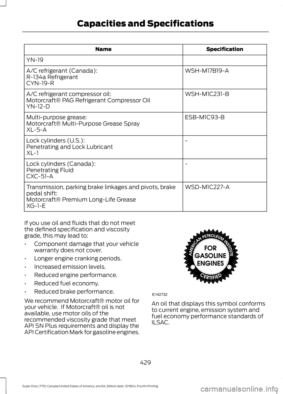
Specification
Name
YN-19 WSH-M17B19-A
A/C refrigerant (Canada):
R-134a Refrigerant
CYN-19-R
WSH-M1C231-B
A/C refrigerant compressor oil:
Motorcraft® PAG Refrigerant Compressor Oil
YN-12-D
ESB-M1C93-B
Multi-purpose grease:
Motorcraft® Multi-Purpose Grease Spray
XL-5-A
-
Lock cylinders (U.S.):
Penetrating and Lock Lubricant
XL-1
-
Lock cylinders (Canada):
Penetrating Fluid
CXC-51-A
WSD-M1C227-A
Transmission, parking brake linkages and pivots, brake
pedal shift:
Motorcraft® Premium Long-Life Grease
XG-1-E
If you use oil and fluids that do not meet
the defined specification and viscosity
grade, this may lead to:
• Component damage that your vehicle
warranty does not cover.
• Longer engine cranking periods.
• Increased emission levels.
• Reduced engine performance.
• Reduced fuel economy.
• Reduced brake performance.
We recommend Motorcraft® motor oil for
your vehicle. If Motorcraft® oil is not
available, use motor oils of the
recommended viscosity grade that meet
API SN Plus requirements and display the
API Certification Mark for gasoline engines. An oil that displays this symbol conforms
to current engine, emission system and
fuel economy performance standards of
ILSAC.
429
Super Duty (TFE) Canada/United States of America, enUSA, Edition date: 201804, Fourth-Printing Capacities and SpecificationsE142732