Page 407 of 666

11.
Set all four tires to the recommended
air pressure as indicated on the
Safety Compliance Certification
Label, affixed to either the door hinge
pillar, door-latch post, or the door
edge that meets the door-latch post,
next to the driver seating position or
Tire Label located on the B-Pillar or
the edge of the driver door.
Performing the System Reset Procedure
- Dual Rear Wheel
For further information see
Understanding Your Tire Pressure
Monitoring System and refer to Dual
Rear Wheel, earlier in this section.
Read the entire procedure before
attempting.
1. Drive the vehicle above
20 mph
(32 km/h) for at least two minutes,
then park in a safe location where you
can easily get to all six tires and have
access to an air pump.
2. Place the ignition in the off position and
keep the key in the ignition.
3. Cycle the ignition to the on position with the engine off.
4. Turn the hazard flashers on then off three times. You must accomplish this
within 10 seconds. If you successfully
enter the reset mode, the horn sounds
once, the system indicator flashes and
a message shows in the information
display. If this does not occur, please
try again starting at step 2. If after
repeated attempts to enter the reset
mode, the horn does not sound, the
system indicator does not flash and no
message shows in the information
display, seek service from your
authorized dealer. 5. Train the tire pressure monitoring
system sensors in the tires using the
following system reset sequence
starting with the left front tire in the
following order: Left front - driver side
front tire, Right front - passenger side
front tire, Right outer rear -passenger
side rear outer tire, Right inner rear -
passenger side rear inner tire, Left outer
rear - driver side rear outer tire, Left
inner rear - driver side rear inner tire.
6. Remove the valve cap from the valve stem on the left front tire. Decrease the
air pressure until the horn sounds.
Note: The single horn chirp confirms that
the sensor identification code has been
learned by the module for this position. If a
double horn is heard, the reset procedure
was unsuccessful, and you must repeat it.
7. Remove the valve cap from the valve stem on the right front tire. Decrease
the air pressure until the horn sounds.
8. Remove the valve cap from the valve stem on the right outer rear tire.
Decrease the air pressure until the horn
sounds.
9. Remove the valve cap from the valve stem on the right inner rear tire.
Decrease the air pressure until the horn
sounds.
10. Remove the valve cap from the valve
stem on the left outer rear tire.
Decrease the air pressure until the
horn sounds.
11. Remove the valve cap from the valve
stem on the left inner rear tire.
Decrease the air pressure until the
horn sounds. Training is complete
after the horn sounds for the last tire
trained, the system indicator stops
flashing, and a message is shown in
the information display.
404
Super Duty (TFE) Canada/United States of America, enUSA, Edition date: 201804, Fourth-Printing Wheels and Tires
Page 410 of 666

The usage of a full-size dissimilar spare
wheel and tire assembly can lead to
impairment of the following:
•
Handling, stability and braking
performance.
• Comfort and noise.
• Ground clearance and parking at curbs.
• Winter weather driving capability.
• Wet weather driving capability.
• Four-wheel drive capability. When driving with the full-size dissimilar
spare wheel and tire assembly additional
caution should be given to:
•
Towing a trailer.
• Driving vehicles equipped with a
camper body.
• Driving vehicles with a load on the
cargo rack.
Drive cautiously when using a full-size
dissimilar spare wheel and tire assembly
and seek service as soon as possible.
Location of the Spare Tire and
Tools
If your vehicle is equipped with a spare tire,
jack and associated tools, see the
following table for their locations: Location
Tool
Under the vehicle, just forward of the rearbumper.
Spare tire - pick-up trucks only
Fastened to the floor pan behind the rear-most seat on the passenger side.
Jack
Regular Cab: Fastened to floor behind thedriver seat.
Jack handle, lug wrench, lug wrench exten-
sion - only available on dual rear wheel
vehicles and wheel chock - only available
on single rear wheel vehicles equipped with a diesel engine. Super Cab and Crew Cab: Fastened to the
floor under the rear seat on the driver's side.
Removing the Spare Tire (With
Spare Tire Carrier Only)
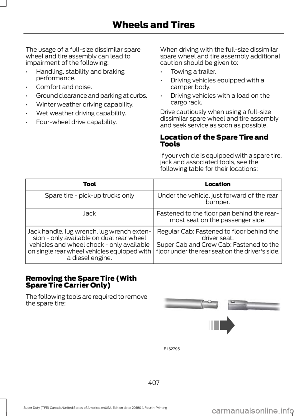
The following tools are required to remove
the spare tire: 407
Super Duty (TFE) Canada/United States of America, enUSA, Edition date: 201804, Fourth-Printing Wheels and TiresE162795
Page 412 of 666

Tire Change Procedure
WARNING: When one of the front
wheels is off the ground, the
transmission alone will not prevent the
vehicle from moving or slipping off the
jack, even if the transmission is in park
(P). WARNING:
To help prevent your
vehicle from moving when changing a
wheel, shift the transmission into park
(P), set the parking brake and use an
appropriate block or wheel chock to
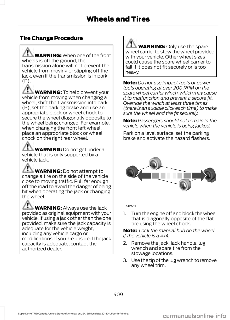
secure the wheel diagonally opposite to
the wheel being changed. For example,
when changing the front left wheel,
place an appropriate block or wheel
chock on the right rear wheel. WARNING:
Do not get under a
vehicle that is only supported by a
vehicle jack. WARNING:
Do not attempt to
change a tire on the side of the vehicle
close to moving traffic. Pull far enough
off the road to avoid the danger of being
hit when operating the jack or changing
the wheel. WARNING:
Always use the jack
provided as original equipment with your
vehicle. If using a jack other than the one
provided, make sure the jack capacity is
adequate for the vehicle weight,
including any vehicle cargo or
modifications. If you are unsure if the jack
capacity is adequate, contact the
authorized dealer. WARNING:
Only use the spare
wheel carrier to stow the wheel provided
with your vehicle. Other wheel sizes
could cause the spare wheel carrier to
fail if it does not fit securely or is too
heavy.
Note: Do not use impact tools or power
tools operating at over 200 RPM on the
spare wheel carrier winch, which may cause
it to malfunction and prevent a secure fit.
Override the winch at least three times
(there is an audible click each time) to make
sure the wheel and tire fit securely.
Note: Passengers should not remain in the
vehicle when the vehicle is being jacked.
Park on a level surface, set the parking
brake and activate the hazard flashers. 1.
Turn the engine off and block the wheel
that is diagonally opposite of the flat
tire using the wheel chock.
Note: Lock the manual hub on the wheel
if the vehicle is a 4x4.
2. Remove the jack, jack handle, lug wrench and spare tire from the
stowage locations.
3. Use the tip of the lug wrench to remove
any wheel trim.
409
Super Duty (TFE) Canada/United States of America, enUSA, Edition date: 201804, Fourth-Printing Wheels and TiresE142551
Page 422 of 666
ENGINE SPECIFICATIONS - 6.2L
6.2L V8 Engine
Engine
379 in³ (6,210 cm³)
Displacement.
Minimum 87 octane
Required fuel.
1-5-4-8-6-3-7-2
Firing order.
Coil on plug
Ignition system.
0.041 in (1.04 mm) - 0.047 in (1.2 mm)
Spark plug gap.
9.8:1
Compression ratio.
Drivebelt Routing ENGINE SPECIFICATIONS - 6.7L DIESEL
6.7L V8 Diesel Engine
Engine
406 in³ (6,651 cm³)
Displacement.
Low Sulfur Diesel up to B20
Required fuel.
1-3-7-2-6-5-4-8
Firing order.
16.2:1
Compression ratio.
419
Super Duty (TFE) Canada/United States of America, enUSA, Edition date: 201804, Fourth-Printing Capacities and SpecificationsE163761
Page 423 of 666
Drivebelt Routing
Single Alternator Dual Alternator
ENGINE SPECIFICATIONS - 6.8L
6.8L V10 Engine
Engine
413
Cubic inches
Minimum 87 octane
Required fuel
1-6-5-10-2-7-3-8-4-9
Firing order
Coil on plug
Ignition system
0.039 - 0.043 in (1.00 - 1.10 mm)
Spark plug gap
9.2:1
Compression ratio
420
Super Duty (TFE) Canada/United States of America, enUSA, Edition date: 201804, Fourth-Printing Capacities and SpecificationsE299020 E299021
Page 424 of 666

Drivebelt Routing
6.8L Engines with A/C 6.8L Engines without A/C
MOTORCRAFT PARTS - 6.2L
Motorcraft Part number
Component
FA-1928
Air filter element.
FL-2077
Crankcase vent filter.
FL-820-S
Oil filter.
BXT-65-650
Battery (XL).
BXT-65-750
Battery (all except XL).
SP-526
Spark plugs-platinum.
WW-2247
Windshield wiper blade.
FT-188
Transmission fluid filter (6R100).
FT-187
Transmission fluid filter (6R140).
FP-79
Cabin air filter.
For scheduled maintenance, we recommend Motorcraft® replacement parts available
at your authorized dealer or at fordparts.com. The parts engineered for your vehicle meet
or exceed our specifications. Use of other parts may impact vehicle performance, emissions
and durability. Your warranty may be void for any damage related to use of other parts.
If a Motorcraft® oil filter is not available, use an oil filter that meets industry performance
specification SAE/USCAR-36.
For spark plug replacement, contact an authorized dealer. Replace the spark plugs at
the appropriate intervals. See Scheduled Maintenance (page 580).
421
Super Duty (TFE) Canada/United States of America, enUSA, Edition date: 201804, Fourth-Printing Capacities and SpecificationsE163762 E163763
Page 425 of 666
MOTORCRAFT PARTS - 6.7L DIESEL
Motorcraft Part number
Component
FL-2051S
Engine oil filter.
FL-2077
Crankcase vent filter.
FA-1927
Foam pre-filter.
FA-1926
Air filter.
FD-4625
Fuel filter.
BXT-65-750
Battery (Two).
WW-2247
Windshield wiper blade.
FP-79
Cabin air filter.
FT-187
Transmission filter.
For scheduled maintenance, we recommend Motorcraft® replacement parts available
at your Ford dealer or at fordparts.com. These parts meet or exceed Ford Motor Company ’s
specifications and are engineered for your vehicle. Use of other parts may impact vehicle
performance, emissions and durability. Your warranty may be void for any damage related
to use of other parts.
If a Motorcraft® oil filter is not available, use an oil filter that meets industry performance
specification SAE/USCAR-36.
422
Super Duty (TFE) Canada/United States of America, enUSA, Edition date: 201804, Fourth-Printing Capacities and Specifications
Page 426 of 666

MOTORCRAFT PARTS - 6.8L
Motorcraft Part number
Component
FA-1928
Air filter element.
FL-2077
Crankcase vent filter.
FL-820-S
Oil filter.
BXT-65-650
Battery (XL).
BXT-65-750
Battery (all except XL).
SP-509
Spark plugs-platinum.
WW-2247
Windshield wiper blade.
FT-187
Transmission fluid filter.
FP-79
Cabin air filter.
For scheduled maintenance, we recommend Motorcraft® replacement parts available
at your Ford dealer or at fordparts.com. These parts meet or exceed Ford Motor Company ’s
specifications and are engineered for your vehicle. Use of other parts may impact vehicle
performance, emissions and durability. Your warranty may be void for any damage related
to use of other parts.
If a Motorcraft® oil filter is not available, use an oil filter that meets industry performance
specification SAE/USCAR-36/USC-D.
For spark plug replacement, contact an authorized dealer. Replace the spark plugs at the
appropriate intervals. See Normal Scheduled Maintenance (page 584).
423
Super Duty (TFE) Canada/United States of America, enUSA, Edition date: 201804, Fourth-Printing Capacities and Specifications