Page 363 of 666

Rear Lamps, Brake Lamps, Rear
Direction Indicator and Reversing
Lamp Bulbs
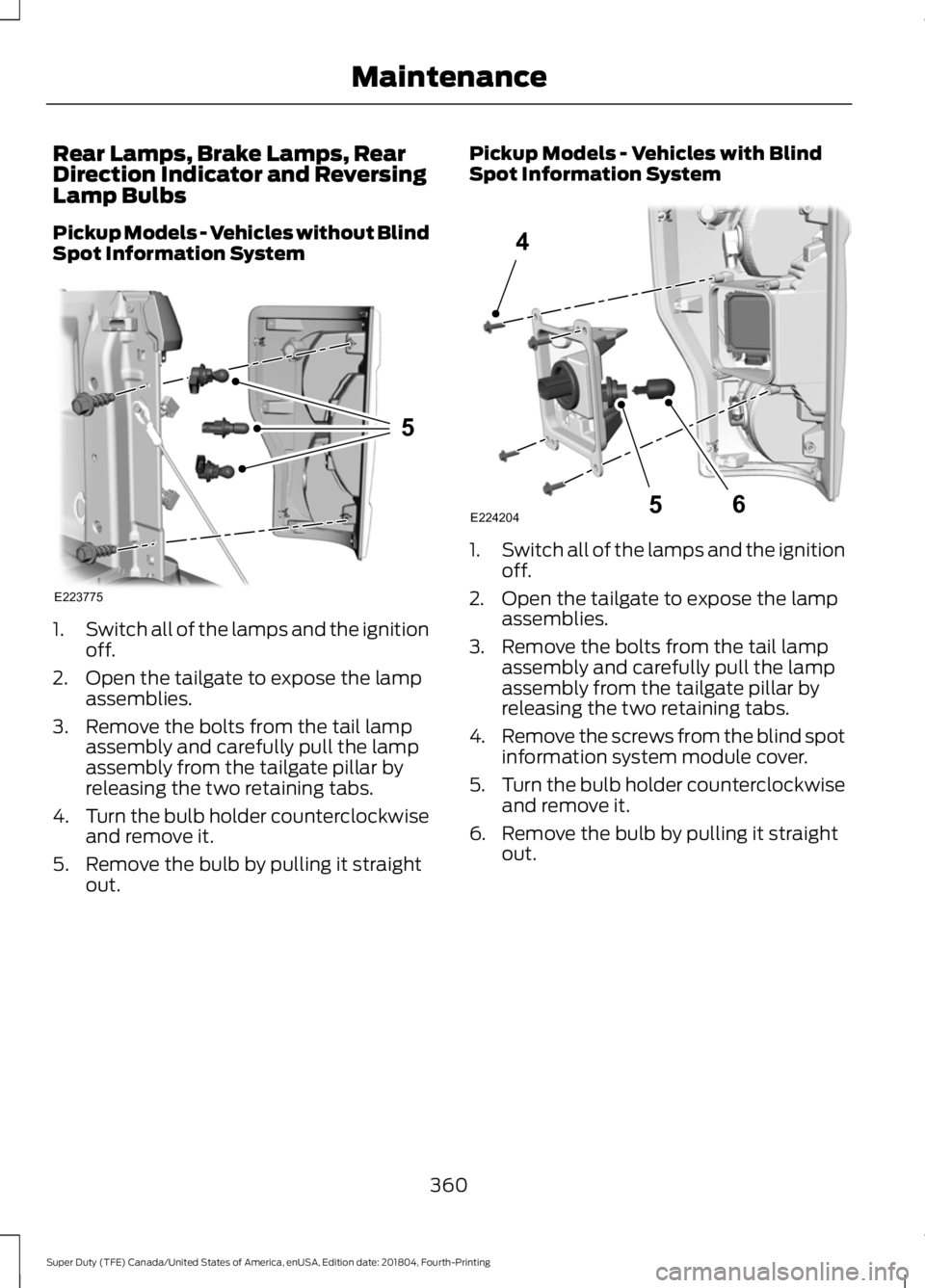
Pickup Models - Vehicles without Blind
Spot Information System
1.
Switch all of the lamps and the ignition
off.
2. Open the tailgate to expose the lamp assemblies.
3. Remove the bolts from the tail lamp assembly and carefully pull the lamp
assembly from the tailgate pillar by
releasing the two retaining tabs.
4. Turn the bulb holder counterclockwise
and remove it.
5. Remove the bulb by pulling it straight out. Pickup Models - Vehicles with Blind
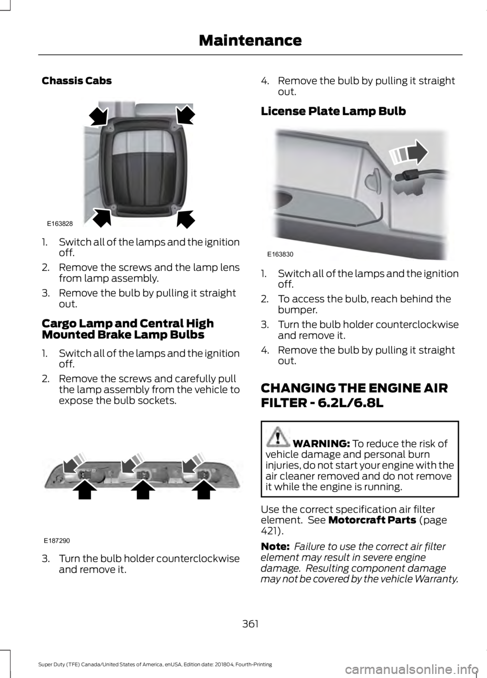
Spot Information System
1.
Switch all of the lamps and the ignition
off.
2. Open the tailgate to expose the lamp assemblies.
3. Remove the bolts from the tail lamp assembly and carefully pull the lamp
assembly from the tailgate pillar by
releasing the two retaining tabs.
4. Remove the screws from the blind spot
information system module cover.
5. Turn the bulb holder counterclockwise
and remove it.
6. Remove the bulb by pulling it straight out.
360
Super Duty (TFE) Canada/United States of America, enUSA, Edition date: 201804, Fourth-Printing MaintenanceE223775
5 E224204
4
65
Page 364 of 666

Chassis Cabs
1.
Switch all of the lamps and the ignition
off.
2. Remove the screws and the lamp lens from lamp assembly.
3. Remove the bulb by pulling it straight out.
Cargo Lamp and Central High
Mounted Brake Lamp Bulbs
1. Switch all of the lamps and the ignition
off.
2. Remove the screws and carefully pull the lamp assembly from the vehicle to
expose the bulb sockets. 3.
Turn the bulb holder counterclockwise
and remove it. 4. Remove the bulb by pulling it straight
out.
License Plate Lamp Bulb 1.
Switch all of the lamps and the ignition
off.
2. To access the bulb, reach behind the bumper.
3. Turn the bulb holder counterclockwise
and remove it.
4. Remove the bulb by pulling it straight out.
CHANGING THE ENGINE AIR
FILTER - 6.2L/6.8L WARNING: To reduce the risk of
vehicle damage and personal burn
injuries, do not start your engine with the
air cleaner removed and do not remove
it while the engine is running.
Use the correct specification air filter
element. See
Motorcraft Parts (page
421).
Note: Failure to use the correct air filter
element may result in severe engine
damage. Resulting component damage
may not be covered by the vehicle Warranty.
361
Super Duty (TFE) Canada/United States of America, enUSA, Edition date: 201804, Fourth-Printing MaintenanceE163828 E187290 E163830
Page 369 of 666

Removal
1. For 2017 models, disconnect the fuel
line quick connect coupling from the in
tank fuel pump. For 2018 models and
later, skip this step but insure that the
fuel filler cap is closed before draining
the filter. Failure to close the fill cap
results in the siphoning of the entire
fuel tank contents when you open the
drain screw.
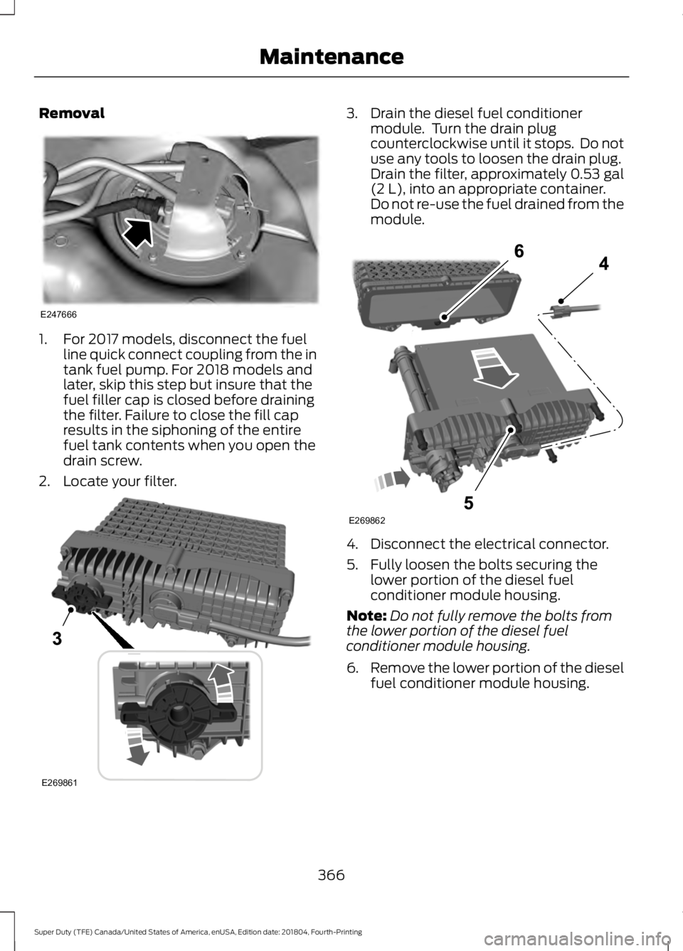
2. Locate your filter. 3. Drain the diesel fuel conditioner
module. Turn the drain plug
counterclockwise until it stops. Do not
use any tools to loosen the drain plug.
Drain the filter, approximately 0.53 gal
(2 L), into an appropriate container.
Do not re-use the fuel drained from the
module. 4. Disconnect the electrical connector.
5. Fully loosen the bolts securing the
lower portion of the diesel fuel
conditioner module housing.
Note: Do not fully remove the bolts from
the lower portion of the diesel fuel
conditioner module housing.
6. Remove the lower portion of the diesel
fuel conditioner module housing.
366
Super Duty (TFE) Canada/United States of America, enUSA, Edition date: 201804, Fourth-Printing MaintenanceE247666 E269861 E269862
Page 370 of 666

7. Slide the filter element toward the
drain plug to disengage the securing
clips.
Installation
1. Slide the filter element into the housing
and fully engage the securing clips.
2. Install the lower portion of the housing.
Tighten the bolts until you feel a strong
resistance. Maximum torque 7 lb.ft
(9 Nm).
3. Connect the electrical connector.
4. Tighten the drain plug, turn it clockwise
until it stops and you feel a strong
resistance. Do not use any tools to
tighten the drain plug.
Engine-mounted Fuel Filter
Although the fuel system is not fully
pressurized when the vehicle is off, some
residual pressure may remain in the fuel
system since it can take some time for the
pressure to completely bleed off.
Therefore, we recommend you place an
absorbent cloth below the filter connectors
to absorb any fuel that may drain. The engine-mounted fuel filter is a plastic
disposable cartridge.
Removal
1.
Disconnect the fuel lines by squeezing
the connector tabs and pulling the lines
straight off. 2.
Rotate the filter fully counterclockwise
until the peg is at the far end of the slot.
3. Pull the filter straight up from the bracket and discard the filter.
367
Super Duty (TFE) Canada/United States of America, enUSA, Edition date: 201804, Fourth-Printing MaintenanceE269863 E226215
1 E226214
2
3
Page 371 of 666
Note:
No special air purge is necessary after
filter servicing. The fuel system purges the
air in the filters.
Installation
1. Install the new filter into the filter bracket. Turn the filter clockwise to
lock it in place.
2. Reconnect the fuel lines.
3. Switch the ignition on for 30 seconds and then switch the ignition off.
Repeat this operation six times in a row
to purge any trapped air from the fuel
system.
368
Super Duty (TFE) Canada/United States of America, enUSA, Edition date: 201804, Fourth-Printing Maintenance
Page 406 of 666

•
To reduce the chances of interference
from another vehicle, perform the
system reset procedure at least 3 ft
(1 m) away from another Ford Motor
Company vehicle undergoing the
system reset procedure at the same
time.
• Do not wait more than two minutes
between resetting each tire sensor or
the system can time-out and you have
to repeat the entire procedure on all
four wheels.
• A double horn sounds indicating the
need to repeat the procedure.
Performing the System Reset Procedure
- Single Rear Wheel
Read the entire procedure before
attempting.
1. Drive the vehicle above
20 mph
(32 km/h) for at least two minutes,
then park in a safe location where you
can easily get to all four tires and have
access to an air pump.
2. Place the ignition in the off position and
keep the key in the ignition.
3. Cycle the ignition to the on position with the engine off.
4. Turn the hazard flashers on then off three times. You must accomplish this
within 10 seconds. If you successfully
enter the reset mode, the horn sounds
once, the system indicator flashes and
a message shows in the information
display. If this does not occur, please
try again starting at step 2. If after
repeated attempts to enter the reset
mode, the horn does not sound, the
system indicator does not flash and no
message shows in the information
display, seek service from your
authorized dealer. 5. Train the tire pressure monitoring
system sensors in the tires using the
following system reset sequence
starting with the left front tire in the
following clockwise order: Left front -
driver side front tire, Right front -
passenger side front tire, Right rear -
passenger side rear tire, Left rear -
driver side rear tire.
6. Remove the valve cap from the valve stem on the left front tire. Decrease the
air pressure until the horn sounds.
Note: The single horn tone confirms that
the sensor identification code has been
learned by the module for this position. If a
double horn is heard, the reset procedure
was unsuccessful, and you must repeat it.
7. Remove the valve cap from the valve stem on the right front tire. Decrease
the air pressure until the horn sounds.
8. Remove the valve cap from the valve stem on the right rear tire. Decrease the
air pressure until the horn sounds.
9. Remove the valve cap from the valve stem on the left rear tire. Decrease the
air pressure until the horn sounds.
Training is complete after the horn
sounds for the last tire trained, driver
side rear tire, the system indicator
stops flashing, and a message shows
in the information display.
10. Turn the ignition off. If two short horn
beeps are heard, the reset procedure
was unsuccessful and you must
repeat it. If after repeating the
procedure and two short beeps are
heard when the ignition is turned to
off, seek assistance from your
authorized dealer.
403
Super Duty (TFE) Canada/United States of America, enUSA, Edition date: 201804, Fourth-Printing Wheels and Tires
Page 411 of 666

One or more handle extensions are used
to operate the spare tire carrier. To
assemble, align the button with the hole
and slide the parts together.
To disconnect, press the button and pull
apart.
The lug wrench is used to turn the handle
extensions and the jack handle, slide the
square end of the handle extension into
the square hole of the lug wrench until it
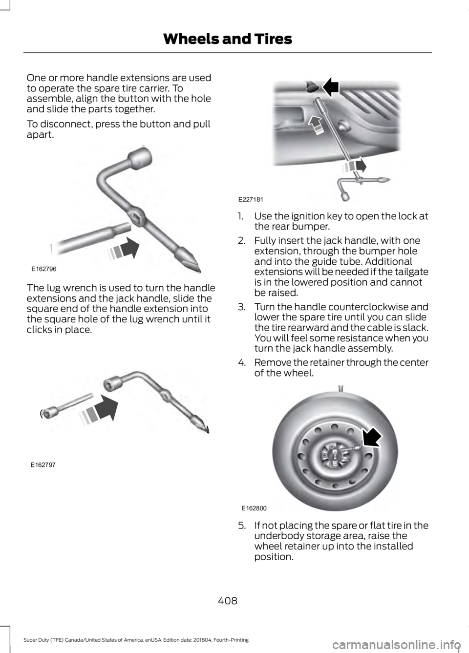
clicks in place. 1.
Use the ignition key to open the lock at
the rear bumper.
2. Fully insert the jack handle, with one extension, through the bumper hole
and into the guide tube. Additional
extensions will be needed if the tailgate
is in the lowered position and cannot
be raised.
3. Turn the handle counterclockwise and
lower the spare tire until you can slide
the tire rearward and the cable is slack.
You will feel some resistance when you
turn the jack handle assembly.
4. Remove the retainer through the center
of the wheel. 5.
If not placing the spare or flat tire in the
underbody storage area, raise the
wheel retainer up into the installed
position.
408
Super Duty (TFE) Canada/United States of America, enUSA, Edition date: 201804, Fourth-Printing Wheels and TiresE162796 E162797 E227181 E162800
Page 413 of 666
4. Loosen each wheel lug nut ½ turn
counterclockwise, but do not remove
them until the wheel is raised off the
ground.
Note: For vehicles with dual rear wheels,
insert the lug wrench extension into the lug
wrench to reach the lug nuts.
F-250 and F-350 Single Rear Wheel
Vehicles 1. Insert the hooked end of the jack
handle into the jack and turn the
handle clockwise until the wheel is
completely off the ground and high
enough to install the spare tire.
2. Position the jack according to the following guides: Front (4x2) Front driver side (4x4)
Note:
Make sure the jack fits onto the flat
area on the outboard side of the differential. Front passenger side (4x4)
Note:
View shown from the rear of the
vehicle to clearly identify the jack point.
Place the jack directly under the axle. 410
Super Duty (TFE) Canada/United States of America, enUSA, Edition date: 201804, Fourth-Printing Wheels and TiresE162801 E162802 E162803 E162804 E162805