2019 FORD F-350 tow bar
[x] Cancel search: tow barPage 78 of 666

7. Disconnect the other cable.
8. Lift the tailgate to a 45 degree angle
from horizontal.
9. Lift the right side off its hinge.
10. Lift the tailgate to an 80 degree angle
from horizontal.
11. Remove the tailgate from the left side
hinge by sliding it to the right.
Reverse the steps to reinstall the tailgate.
TAILGATE STEP (IF EQUIPPED)
Use the step to make entering the truck
bed easier.
To reduce the risk of falling:
• Only operate the step when your
vehicle is on a level surface.
• Only operate the step in areas with
sufficient lighting.
• Always open the step panel to widen
the step.
• Always use the grab handle when
climbing on the step.
• Do not use the step with bare feet.
• Make sure the step is clean before use.
• Keep the step load, you plus the load,
below
350 lb (159 kg).
Opening the Step
Note: Make sure to close and fully latch the
step before moving your vehicle. Do not
drive with the step or grab handle open.
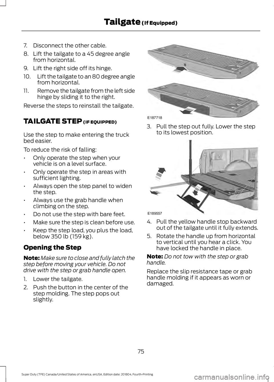
1. Lower the tailgate.
2. Push the button in the center of the step molding. The step pops out
slightly. 3. Pull the step out fully. Lower the step
to its lowest position. 4. Pull the yellow handle stop backward
out of the tailgate until it fully extends.
5. Rotate the handle up from horizontal to vertical until you hear a click. You
have locked the handle in place.
Note: Do not tow with the step or grab
handle.
Replace the slip resistance tape or grab
handle molding if it appears as worn or
damaged.
75
Super Duty (TFE) Canada/United States of America, enUSA, Edition date: 201804, Fourth-Printing Tailgate
(If Equipped)E187718 E189557
Page 249 of 666

Automatic Cancellation
The system is not functional at vehicle
speeds below 12 mph (20 km/h). The
information display indicates low engine
speed, an audible alarm sounds and the
automatic braking releases if the vehicle
drops below this speed.
Automatic cancellation can also occur
when:
•
The tires lose traction.
• You apply the parking brake.
Note: If the engine speed drops too low, an
audible warning sounds and a message
appears in the information display.
Automatic braking releases.
Hilly Condition and Trailer Tow
Usage
You should select a lower gear when the
system is active in situations such as
prolonged downhill driving on steep
grades, for example in mountainous areas.
The system needs additional engine
braking in these situations to reduce the
load on the vehicle ’s regular brake system
to prevent it from overheating.
Note: An audible alarm sounds and the
system shuts down if it applies brakes for
an extended period of time. This allows the
brakes to cool. The system functions
normally again after the brakes cool.
Note: When towing with adaptive cruise
control, switch on Tow/Haul Mode and
Diesel Engine Brake.
Note: Tow/Haul mode increases the time
gaps and allows more distance for braking.
Switching Adaptive Cruise Control
Off Press and release the button
when the system is in standby
mode, or switch the ignition off. Note:
You erase the set speed and gap
setting when you switch the system off.
Detection Issues WARNING: On rare occasions,
detection issues can occur due to the
road infrastructures, for example bridges,
tunnels and safety barriers. In these
cases, the system may brake late or
unexpectedly. At all times, you are
responsible for controlling your vehicle,
supervising the system and intervening,
if required. WARNING:
If the system
malfunctions, have your vehicle checked
as soon as possible.
The radar sensor has a limited field of view.
It may not detect vehicles at all or detect
a vehicle later than expected in some
situations. The lead vehicle graphic does
not illuminate if the system does not
detect a vehicle in front of you.
246
Super Duty (TFE) Canada/United States of America, enUSA, Edition date: 201804, Fourth-Printing Cruise Control
(If Equipped)E265297
Page 258 of 666

The system uses radar sensors that are
located inside the tail lamp on each side
of your vehicle. Any dirt, mud and snow in
front of the sensors or driving in heavy rain
can cause system degradation. Also, other
types of obstructions in front of the sensor
can cause system degradation. This is
referred to as a
‘blocked ’ condition.
Note: Do not apply bumper stickers and/or
repair compound to these areas, this can
cause degraded system performance.
If the system detects a degraded
performance condition, a message warning
appears in the display screen. The alert
indicators remain ON and the system no
longer provides any warnings. You can
clear the warning but the alert indicators
remain illuminated.
A "blocked" condition can be cleared in
two ways:
• After the blockage in front of the
sensors is removed or the
rainfall/snowfall rate decreases or
stops, drive for a few minutes in traffic
to allow the sensors to detect passing
vehicles.
• By cycling the ignition from ON to OFF
and then back ON.
Note: If your vehicle has a tow bar with a
factory equipped trailer tow module and it
is towing a trailer, the sensors will
automatically turn the Blind Spot
Information System off. If your vehicle has
a tow bar but no factory equipped trailer
tow module, it is recommended to turn the
Blind Spot Information System off
manually. Operating the Blind Spot
Information System without the Blind Spot
Trailer Tow package and a trailer attached
will cause poor system performance. Blind Spot Information System
with Trailer Tow (If Equipped)
The Blind Spot Information System with
Trailer Tow is designed to aid you in
detecting vehicles that may have entered
the detection area zone (A). The detection
area is on both sides of your vehicle and
trailer, extending rearward from the
exterior mirrors to the end of your trailer.
When a trailer is attached and the
customer has set up a Blind Spot Trailer,
the Blind Spot Information System with
Trailer Tow becomes active when driving
forward above
6 mph (10 km/h). See
Trailer Reversing Aids (page 275).
The Blind Spot Information System with
Trailer Tow can be turned off in the
instrument cluster. If the Blind Spot
Information System is turned off, then the
Blind Spot Information System with Trailer
Tow automatically turns off.
255
Super Duty (TFE) Canada/United States of America, enUSA, Edition date: 201804, Fourth-Printing Driving AidsE225007
Page 263 of 666

System Limitations
Cross Traffic Alert has its limitations;
situations such as severe weather
conditions or debris build-up on the sensor
area may limit vehicle detection and cause
false alerts.
The following are other situations that may
limit the Cross Traffic Alert performance:
•
Adjacently parked vehicles or objects
obstructing the sensors.
• Approaching vehicles passing at
speeds greater than 37 mph
(60 km/h).
• Driving in reverse faster than
7 mph
(12 km/h).
• Backing out of an angled parking spot.
False Alerts
Note: If your vehicle has a tow bar with a
factory equipped trailer tow module and it
is towing a trailer, the sensors will
automatically turn the Cross Traffic Alert
off. If your vehicle has a tow bar but no
factory equipped trailer tow module, it is
recommended to turn the Cross Traffic Alert
off manually. Operating Cross Traffic Alert
with a trailer attached will cause poor Cross
Traffic Alert performance.
Note: The system may illuminate the amber
alert indicator and sound the audible alert
during heavy rain even though no vehicle is
approaching from left or right.
There may be certain instances when there
is a false alert by the Cross Traffic Alert
system that illuminates the alert indicator
with no vehicle in the coverage zone. Some
amount of false alerts are normal; they are
temporary and self-correct. System Errors
If Cross Traffic Alert senses a problem with
the left or right sensor a message appears
in the display screen. See
Information
Messages (page 128).
Switching the System Off and On
Note: The Cross Traffic Alert switches on
whenever the ignition is switched on and
ready to provide appropriate alerts when
the transmission is in reverse (R). Cross
Traffic Alert will not remember the last
selected on or off setting.
You can temporarily switch Cross Traffic
Alert off in the information display. See
General Information
(page 112). When
you switch Cross Traffic Alert off, you do
not receive alerts and the display screen
shows a system off message.
You can also have Cross Traffic Alert
switched off permanently at an authorized
dealer. Once switched off permanently,
the system can only be switched back on
at an authorized dealer.
STEERING
Hydraulic Power Steering
To help prevent damage to the power
steering system:
• Do not hold the steering wheel at its
furthest turning points for more than
three to five seconds when the engine
is running.
• Avoid continuously steering back and
forth with elevated engine RPM as this
may overheat the system. If trying to
free a stuck vehicle, pause between
attempts to allow the power steering
system to cool or seek assistance.
Typical steering and driving maneuvers
allow the system to cool.
260
Super Duty (TFE) Canada/United States of America, enUSA, Edition date: 201804, Fourth-Printing Driving Aids
Page 283 of 666

The following menu warnings or difficulties
may occur during setup. Tips to resolve
them are listed below.
Measurement A has reached maximum or
minimum value:
•
The system is designed to work with
drawbars that have a license plate to
hitch ball center measurement of
9–16 in (229–406 mm) when installed.
Do not attempt to use drawbars that
have a length outside this range as
system performance degrades and
could cause improper system function.
• Make sure that the measurement being
made is the horizontal distance only
from license plate and the hitch ball
center. A straight line distance that
includes any vertical rise or drop
increases the measurement and makes
it inaccurate. Inaccurate
measurements degrade system
performance and could cause improper
system function. See step 4 of the
setup instruction to review the
measurement instructions.
Measurement B has reached maximum or
minimum value:
• Make sure you follow the sticker
placement instruction in step 3 of the
setup. Stickers placed outside the
allowed zone adversely affect the
system performance and could cause
improper feature function.
• Make sure that the measurement being
made is the horizontal distance only
from center of sticker to the hitch ball
center. A straight line distance that
includes any vertical rise or drop
increases the measurement and
causes an inaccurate value to be
entered into the system. See step 4 of
the setup for additional measurement
instructions. Measurement C has reached maximum or
minimum value:
•
Make sure you follow the sticker
placement instructions in step 3 of the
setup. Stickers placed outside the
allowed zone adversely affect the
system performance and could cause
improper feature function. If you have
met all the criteria for sticker
placement and you see this message,
the sticker is either too far below or too
close to the camera to properly
recognize the sticker. In order for the
system to correctly operate, the sticker
height must be lowered if you receive
the minimum warning or the sticker
height must be raised if you receive the
maximum warning.
•Only one sticker can be placed on
the trailer for correct system
function. The previous sticker must
be removed or covered so only one
sticker is visible to the camera.
• Measurement B and C must be
measured again if a new sticker is
placed on the trailer.
Measurement D has reached maximum or
minimum value:
• Make sure that the measurement being
made is the horizontal distance only
from tailgate to the center of the single
axle or the center of all the axles on the
trailer. See step 4 of the setup for
additional measurement instructions.
The system does not support trailer
lengths outside the range allowed by
the information display.
280
Super Duty (TFE) Canada/United States of America, enUSA, Edition date: 201804, Fourth-Printing Towing
Page 285 of 666

remove the sticker from its current
location if the obstruction cannot
be cleared. Place a new sticker that
is visible to the camera in all
positions of the trailer behind your
vehicle.
• You can change your sticker
location by going into the trailer
menu, selecting trailer options,
selecting change trailer settings
and then selecting the change
sticker option. The previous sticker
must be removed. ONLY ONE
STICKER SHOULD BE PLACED
ON THE TRAILER FOR CORRECT
SYSTEM FUNCTION.
• The camera system uses the
entered measurements to help
locate the sticker. Inaccurate
measurements reduce the system ’s
ability to locate the sticker. Check
the measurements entered into the
system are correct. Refer to the
step 4 of trailer reverse guidance
setup for instructions on
measurements.
• You can change your measurement
by going into the trailer menu,
selecting trailer options, selecting
change trailer setting and then
selecting the change sticker option.
Disregard the prompt to remove
this sticker and continue to the next
step if you only plan to update the
measurements for the current
sticker location.
System does not backup straight:
• Factors such as the drawbar
connection to the hitch receiver, road
camber, road grade and compliance in
the trailer suspension can influence
how straight the system is able to
reverse your trailer when the wheel is
not turned. You can compensate for
the trailer drifting to the right or left by slowly turning the wheel until the trailer
is following your desired path and then
holding the wheel in that position. If
you would like to recalibrate the
system for straight backing, you can do
so with the following procedure.
•
Go into the trailer menu, select
trailer options, select change trailer
setting and then select the change
sticker option. Your saved
measurements show. Do not
change them, but continue to
confirm measurements. Once you
confirm the measurements, the
system then prompts you to
perform the calibration procedure.
Note: The system is designed to be used
with the same trailer connection every time
the trailer is chosen from the selection
menu. Using a different drawbar or a
different pin hole, on drawbars with more
than one pin hole, when connecting the
drawbar to your vehicle affects the trailer
measurements. Take the measurements
again and update if required.
TRAILER SWAY CONTROL (IF
EQUIPPED) WARNING: Turning off trailer sway
control increases the risk of loss of
vehicle control, serious injury or death.
Ford does not recommend disabling this
feature except in situations where speed
reduction may be detrimental (such as
hill climbing), the driver has significant
trailer towing experience, and can control
trailer sway and maintain safe operation.
Note: This feature does not prevent trailer
sway, but reduces it once it begins.
Note: This feature cannot stop all trailers
from swaying.
282
Super Duty (TFE) Canada/United States of America, enUSA, Edition date: 201804, Fourth-Printing Towing
Page 286 of 666

Note:
In some cases, if vehicle speed is too
high, the system may activate multiple
times, gradually reducing vehicle speed.
This feature applies your vehicle brakes at
individual wheels and, if necessary, reduces
engine power. If the trailer begins to sway,
the stability control light flashes and the
message TRAILER SWAY REDUCE
SPEED appears in the information display.
The first thing to do is slow your vehicle
down, then pull safely to the side of the
road and check for proper tongue load and
trailer load distribution. See
Load
Carrying (page 266).
RECOMMENDED TOWING
WEIGHTS WARNING:
You must use
the heavy-duty drawbar pin
supplied with your vehicle when
using the heavy-duty hitch.
Failure to follow this instruction
could result in the loss of control
of your vehicle, personal injury or
death.
Note: Vehicles with a heavy-duty
hitch must use the drawbar pin
stamped 21,000 LBS. You can
obtain a replacement drawbar pin
at your authorized dealer. Note:
Make sure to take into
consideration trailer frontal area.
Do not exceed 60 ft 2
(5.6 m 2
) trailer
frontal area for conventional
trailers. Do not exceed 75 ft 2
(6.9
m 2
) trailer frontal area for fifth
wheel and gooseneck trailers.
Note: Exceeding this limitation
may significantly reduce the
performance of your towing
vehicle. Selecting a trailer with a
low aerodynamic drag and rounded
front design helps optimize
performance and fuel economy.
Note: For high altitude operation,
reduce the gross combined weight
by 2% per 1,000 ft (300 m)
starting at the 1,000 ft (300 m)
elevation point.
Note: Certain states require
electric trailer brakes for trailers
over a specified weight. Be sure to
check state regulations for this
specified weight. The maximum
trailer weights listed may be limited
to this specified weight, as your
vehicle's electrical system may not
include the wiring connector
needed to use electric trailer
brakes.
Your vehicle may tow a trailer
provided the maximum trailer
weight is less than or equal to the
maximum trailer weight
calculated using the formula
following the chart.
283
Super Duty (TFE) Canada/United States of America, enUSA, Edition date: 201804, Fourth-Printing Towing
Page 289 of 666

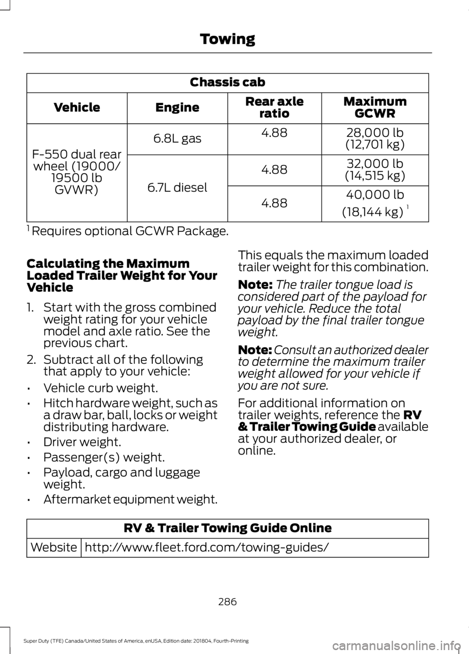
Chassis cab
MaximumGCWR
Rear axle
ratio
Engine
Vehicle
28,000 lb
(12,701 kg)
4.88
6.8L gas
F-550 dual rear wheel (19000/ 19500 lbGVWR) 32,000 lb
(14,515 kg)
4.88
6.7L diesel 40,000 lb
(18,144 kg) 1
4.88
1 Requires optional GCWR Package.
Calculating the Maximum
Loaded Trailer Weight for Your
Vehicle
1. Start with the gross combined weight rating for your vehicle
model and axle ratio. See the
previous chart.
2. Subtract all of the following
that apply to your vehicle:
• Vehicle curb weight.
• Hitch hardware weight, such as
a draw bar, ball, locks or weight
distributing hardware.
• Driver weight.
• Passenger(s) weight.
• Payload, cargo and luggage
weight.
• Aftermarket equipment weight. This equals the maximum loaded
trailer weight for this combination.
Note:
The trailer tongue load is
considered part of the payload for
your vehicle. Reduce the total
payload by the final trailer tongue
weight.
Note: Consult an authorized dealer
to determine the maximum trailer
weight allowed for your vehicle if
you are not sure.
For additional information on
trailer weights, reference the RV
& Trailer Towing Guide available
at your authorized dealer, or
online. RV & Trailer Towing Guide Online
http://www.fleet.ford.com/towing-guides/
Website
286
Super Duty (TFE) Canada/United States of America, enUSA, Edition date: 201804, Fourth-Printing Towing