2019 FORD F-250 buttons
[x] Cancel search: buttonsPage 157 of 666
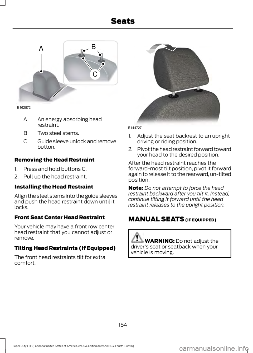
An energy absorbing head
restraint.
A
Two steel stems.
B
Guide sleeve unlock and remove
button.
C
Removing the Head Restraint
1. Press and hold buttons C.
2. Pull up the head restraint.
Installing the Head Restraint
Align the steel stems into the guide sleeves
and push the head restraint down until it
locks.
Front Seat Center Head Restraint
Your vehicle may have a front row center
head restraint that you cannot adjust or
remove.
Tilting Head Restraints (If Equipped)
The front head restraints tilt for extra
comfort. 1. Adjust the seat backrest to an upright
driving or riding position.
2. Pivot the head restraint forward toward
your head to the desired position.
After the head restraint reaches the
forward-most tilt position, pivot it forward
again to release it to the rearward, un-tilted
position.
Note: Do not attempt to force the head
restraint backward after you tilt it. Instead,
continue tilting it forward until the head
restraint releases to the upright position.
MANUAL SEATS (IF EQUIPPED) WARNING:
Do not adjust the
driver's seat or seatback when your
vehicle is moving.
154
Super Duty (TFE) Canada/United States of America, enUSA, Edition date: 201804, Fourth-Printing SeatsE162872
A
C
B E144727
Page 167 of 666
UNIVERSAL GARAGE DOOR
OPENER
HomeLink Wireless Control
System
WARNING: Do not use the system
with any garage door opener that does
not have the safety stop and reverse
feature as required by U.S. Federal
Safety Standards (this includes any
garage door opener manufactured
before April 1, 1982). A garage door
opener which cannot detect an object,
signaling the door to stop and reverse,
does not meet current federal safety
standards. Using a garage door opener
without these features increases the risk
of serious injury or death.
Note: Make sure that the garage door and
security device are free from obstruction
when you are programming. Do not program
the system with the vehicle in the garage.
Note: Make sure you keep the original
remote control transmitter for use in other
vehicles as well as for future system
programming.
Note: We recommend that upon the sale
or lease termination of your vehicle, you
erase the programmed function buttons for
security reasons. See Erasing the Function
Button Codes
later in this section.
Note: You can program a maximum of
three devices. To change or replace any of
the three devices after it has been initially
programmed, you must first erase the
current settings. See Erasing the Function
Button Codes
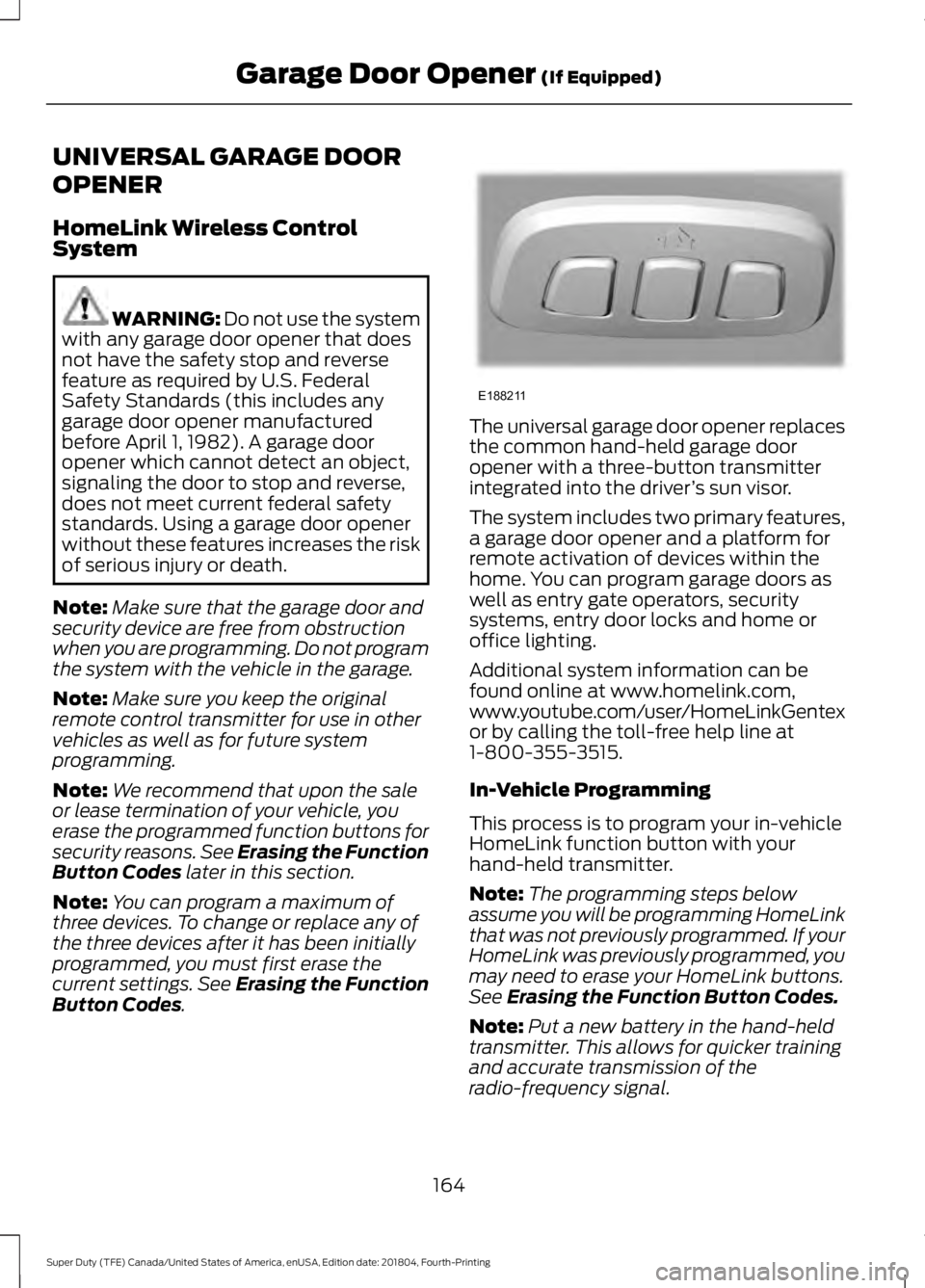
. The universal garage door opener replaces
the common hand-held garage door
opener with a three-button transmitter
integrated into the driver
’s sun visor.
The system includes two primary features,
a garage door opener and a platform for
remote activation of devices within the
home. You can program garage doors as
well as entry gate operators, security
systems, entry door locks and home or
office lighting.
Additional system information can be
found online at www.homelink.com,
www.youtube.com/user/HomeLinkGentex
or by calling the toll-free help line at
1-800-355-3515.
In-Vehicle Programming
This process is to program your in-vehicle
HomeLink function button with your
hand-held transmitter.
Note: The programming steps below
assume you will be programming HomeLink
that was not previously programmed. If your
HomeLink was previously programmed, you
may need to erase your HomeLink buttons.
See Erasing the Function Button Codes.
Note: Put a new battery in the hand-held
transmitter. This allows for quicker training
and accurate transmission of the
radio-frequency signal.
164
Super Duty (TFE) Canada/United States of America, enUSA, Edition date: 201804, Fourth-Printing Garage Door Opener
(If Equipped)E188211
Page 168 of 666
1.
With your vehicle parked outside of the
garage, switch your ignition to the on
position, but do not start your vehicle.
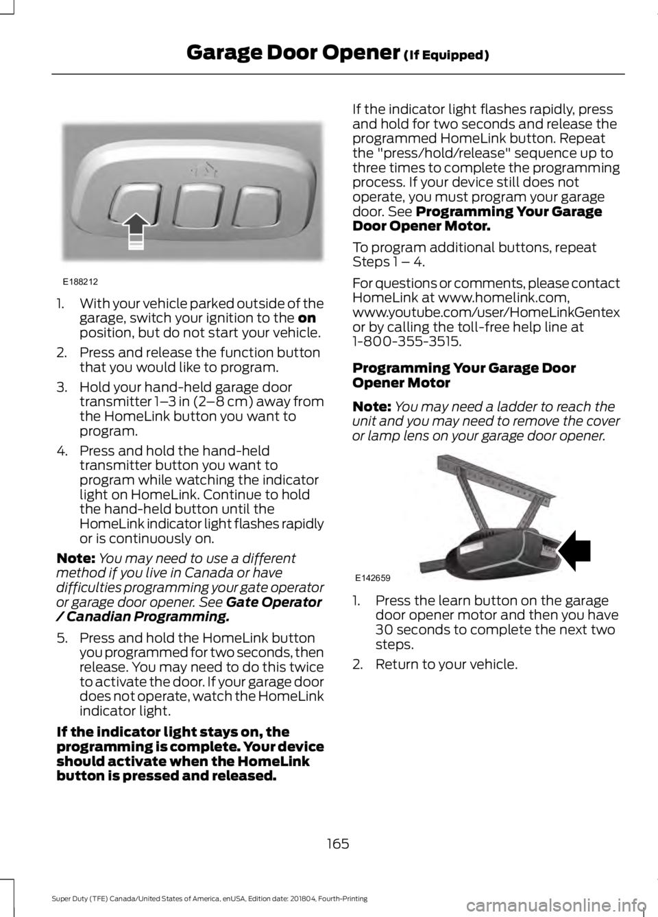
2. Press and release the function button that you would like to program.
3. Hold your hand-held garage door transmitter 1– 3 in (2–8 cm) away from
the HomeLink button you want to
program.
4. Press and hold the hand-held transmitter button you want to
program while watching the indicator
light on HomeLink. Continue to hold
the hand-held button until the
HomeLink indicator light flashes rapidly
or is continuously on.
Note: You may need to use a different
method if you live in Canada or have
difficulties programming your gate operator
or garage door opener. See
Gate Operator
/ Canadian Programming.
5. Press and hold the HomeLink button you programmed for two seconds, then
release. You may need to do this twice
to activate the door. If your garage door
does not operate, watch the HomeLink
indicator light.
If the indicator light stays on, the
programming is complete. Your device
should activate when the HomeLink
button is pressed and released. If the indicator light flashes rapidly, press
and hold for two seconds and release the
programmed HomeLink button. Repeat
the "press/hold/release" sequence up to
three times to complete the programming
process. If your device still does not
operate, you must program your garage
door. See
Programming Your Garage
Door Opener Motor.
To program additional buttons, repeat
Steps 1 – 4.
For questions or comments, please contact
HomeLink at www.homelink.com,
www.youtube.com/user/HomeLinkGentex
or by calling the toll-free help line at
1-800-355-3515.
Programming Your Garage Door
Opener Motor
Note: You may need a ladder to reach the
unit and you may need to remove the cover
or lamp lens on your garage door opener. 1. Press the learn button on the garage
door opener motor and then you have
30 seconds to complete the next two
steps.
2. Return to your vehicle.
165
Super Duty (TFE) Canada/United States of America, enUSA, Edition date: 201804, Fourth-Printing Garage Door Opener
(If Equipped)E188212 E142659
Page 169 of 666
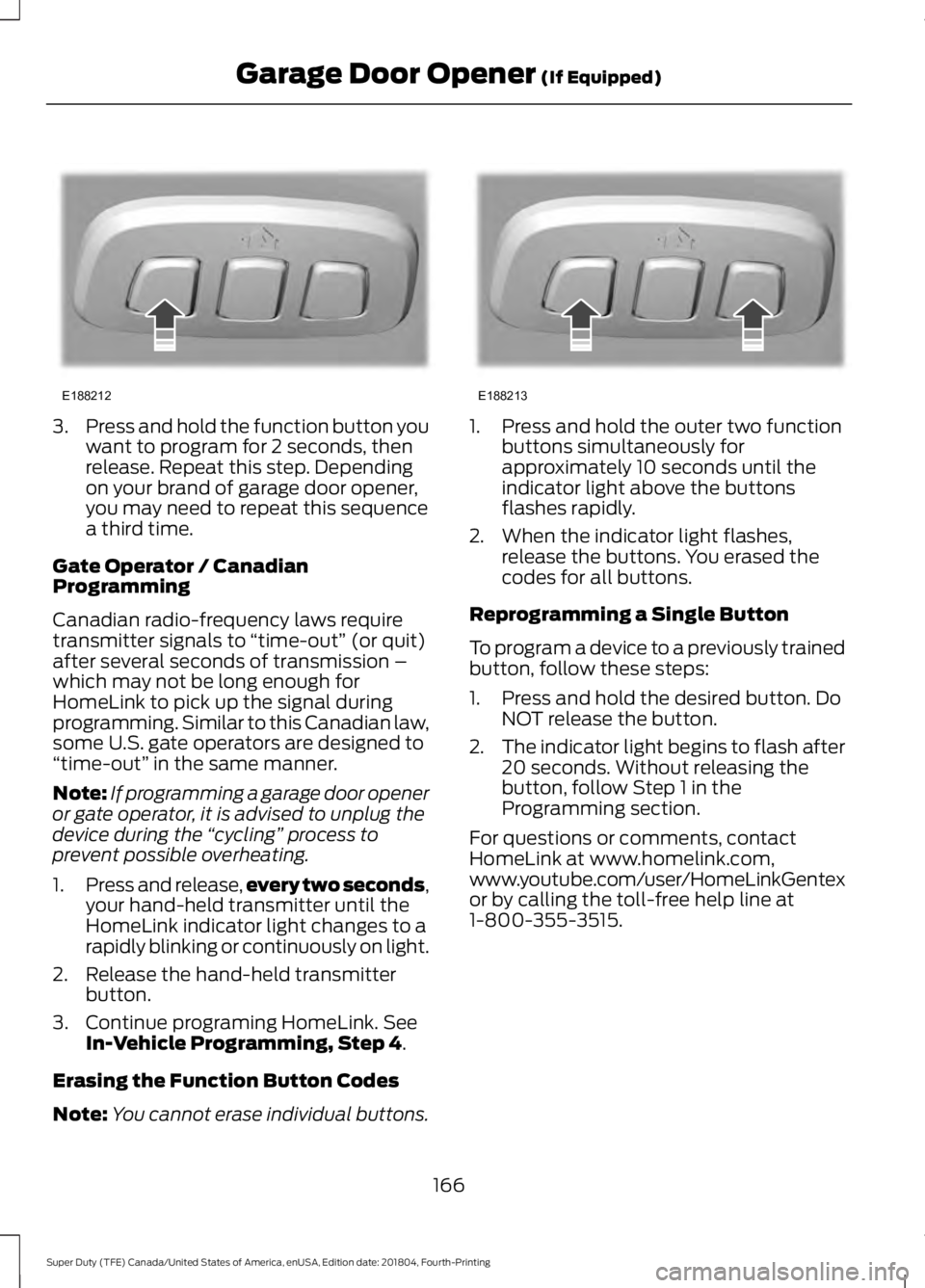
3.
Press and hold the function button you
want to program for 2 seconds, then
release. Repeat this step. Depending
on your brand of garage door opener,
you may need to repeat this sequence
a third time.
Gate Operator / Canadian
Programming
Canadian radio-frequency laws require
transmitter signals to “time-out” (or quit)
after several seconds of transmission –
which may not be long enough for
HomeLink to pick up the signal during
programming. Similar to this Canadian law,
some U.S. gate operators are designed to
“time-out” in the same manner.
Note: If programming a garage door opener
or gate operator, it is advised to unplug the
device during the “cycling” process to
prevent possible overheating.
1. Press and release, every two seconds,
your hand-held transmitter until the
HomeLink indicator light changes to a
rapidly blinking or continuously on light.
2. Release the hand-held transmitter button.
3. Continue programing HomeLink. See In-Vehicle Programming, Step 4.
Erasing the Function Button Codes
Note: You cannot erase individual buttons. 1. Press and hold the outer two function
buttons simultaneously for
approximately 10 seconds until the
indicator light above the buttons
flashes rapidly.
2. When the indicator light flashes, release the buttons. You erased the
codes for all buttons.
Reprogramming a Single Button
To program a device to a previously trained
button, follow these steps:
1. Press and hold the desired button. Do NOT release the button.
2. The indicator light begins to flash after
20 seconds. Without releasing the
button, follow Step 1 in the
Programming section.
For questions or comments, contact
HomeLink at www.homelink.com,
www.youtube.com/user/HomeLinkGentex
or by calling the toll-free help line at
1-800-355-3515.
166
Super Duty (TFE) Canada/United States of America, enUSA, Edition date: 201804, Fourth-Printing Garage Door Opener
(If Equipped)E188212 E188213
Page 209 of 666
AUTOMATIC TRANSMISSION
WARNING: Always fully apply the
parking brake. Make sure you shift into
park (P) for vehicles with an automatic
transmission. Switch the ignition off and
remove the key whenever you leave your
vehicle. WARNING:
When your vehicle is
stationary, keep the brake pedal fully
pressed when shifting gears. Failure to
follow this instruction could result in
personal injury, death or property
damage.
Note: You may not be able to shift out of
park (P) unless the intelligent access key is
inside your vehicle.
Understanding the Shift Positions
of Your Automatic Transmission
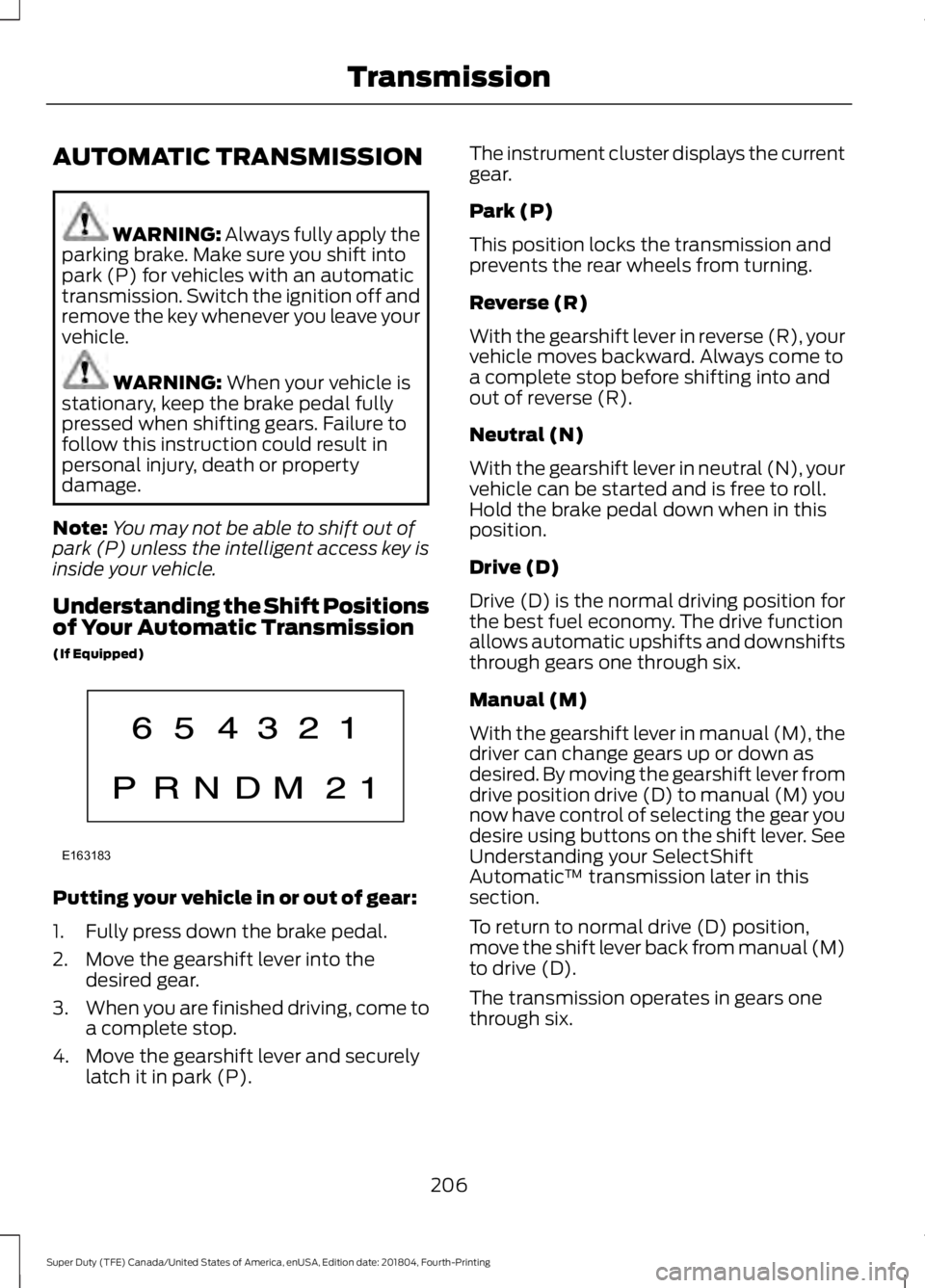
(If Equipped) Putting your vehicle in or out of gear:
1. Fully press down the brake pedal.
2. Move the gearshift lever into the
desired gear.
3. When you are finished driving, come to
a complete stop.
4. Move the gearshift lever and securely latch it in park (P). The instrument cluster displays the current
gear.
Park (P)
This position locks the transmission and
prevents the rear wheels from turning.
Reverse (R)
With the gearshift lever in reverse (R), your
vehicle moves backward. Always come to
a complete stop before shifting into and
out of reverse (R).
Neutral (N)
With the gearshift lever in neutral (N), your
vehicle can be started and is free to roll.
Hold the brake pedal down when in this
position.
Drive (D)
Drive (D) is the normal driving position for
the best fuel economy. The drive function
allows automatic upshifts and downshifts
through gears one through six.
Manual (M)
With the gearshift lever in manual (M), the
driver can change gears up or down as
desired. By moving the gearshift lever from
drive position drive (D) to manual (M) you
now have control of selecting the gear you
desire using buttons on the shift lever. See
Understanding your SelectShift
Automatic
™ transmission later in this
section.
To return to normal drive (D) position,
move the shift lever back from manual (M)
to drive (D).
The transmission operates in gears one
through six.
206
Super Duty (TFE) Canada/United States of America, enUSA, Edition date: 201804, Fourth-Printing TransmissionE163183
Page 211 of 666
Understanding your SelectShift
Automatic
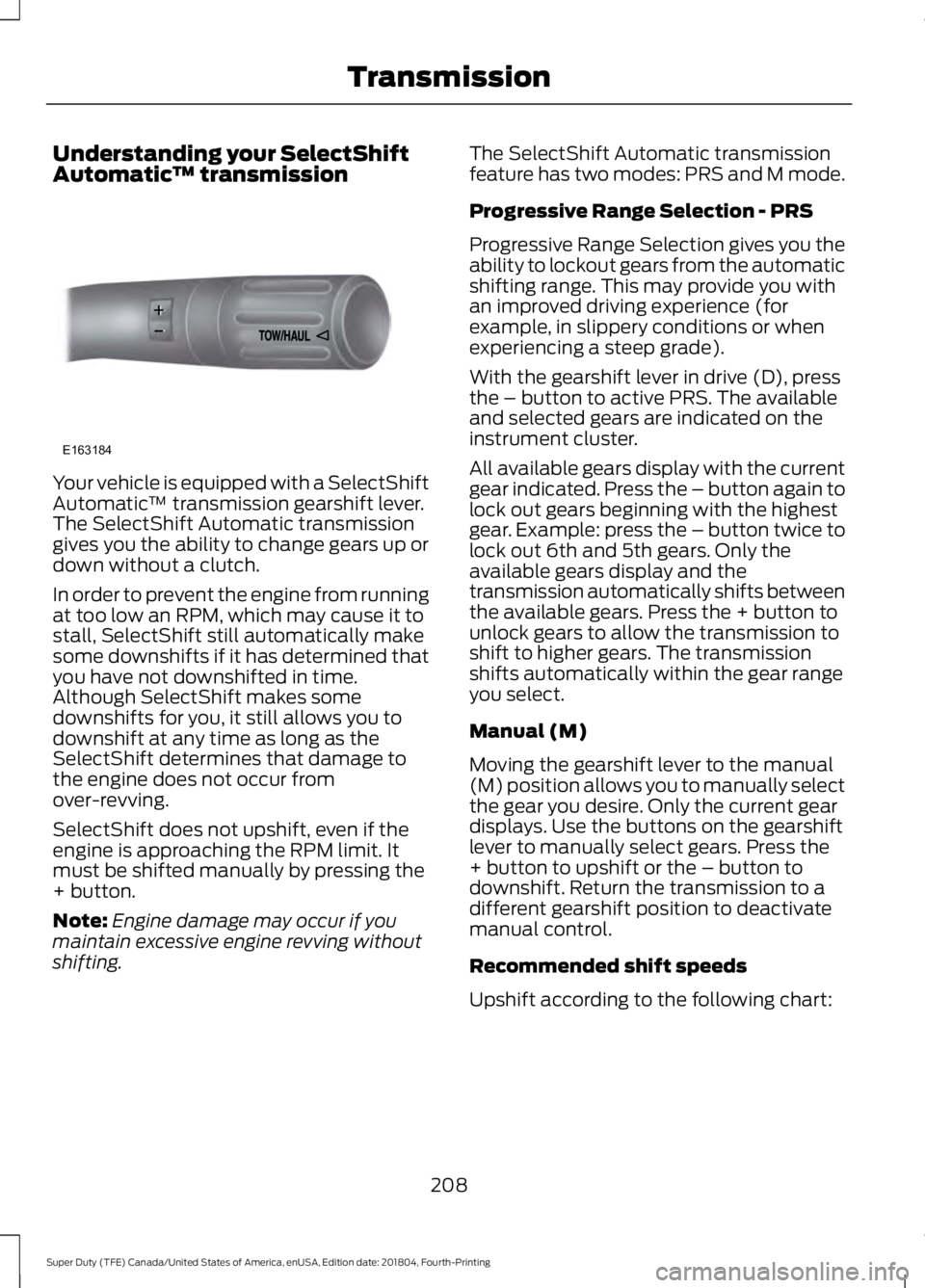
™ transmissionYour vehicle is equipped with a SelectShift
Automatic
™ transmission gearshift lever.
The SelectShift Automatic transmission
gives you the ability to change gears up or
down without a clutch.
In order to prevent the engine from running
at too low an RPM, which may cause it to
stall, SelectShift still automatically make
some downshifts if it has determined that
you have not downshifted in time.
Although SelectShift makes some
downshifts for you, it still allows you to
downshift at any time as long as the
SelectShift determines that damage to
the engine does not occur from
over-revving.
SelectShift does not upshift, even if the
engine is approaching the RPM limit. It
must be shifted manually by pressing the
+ button.
Note: Engine damage may occur if you
maintain excessive engine revving without
shifting. The SelectShift Automatic transmission
feature has two modes: PRS and M mode.
Progressive Range Selection - PRS
Progressive Range Selection gives you the
ability to lockout gears from the automatic
shifting range. This may provide you with
an improved driving experience (for
example, in slippery conditions or when
experiencing a steep grade).
With the gearshift lever in drive (D), press
the – button to active PRS. The available
and selected gears are indicated on the
instrument cluster.
All available gears display with the current
gear indicated. Press the – button again to
lock out gears beginning with the highest
gear. Example: press the – button twice to
lock out 6th and 5th gears. Only the
available gears display and the
transmission automatically shifts between
the available gears. Press the + button to
unlock gears to allow the transmission to
shift to higher gears. The transmission
shifts automatically within the gear range
you select.
Manual (M)
Moving the gearshift lever to the manual
(M) position allows you to manually select
the gear you desire. Only the current gear
displays. Use the buttons on the gearshift
lever to manually select gears. Press the
+ button to upshift or the – button to
downshift. Return the transmission to a
different gearshift position to deactivate
manual control.
Recommended shift speeds
Upshift according to the following chart:
208
Super Duty (TFE) Canada/United States of America, enUSA, Edition date: 201804, Fourth-Printing TransmissionE163184
Page 259 of 666

Setting up a Blind Spot Trailer
Trailer length
A
Trailer width
B
Trailer hitch ball
C
You can set-up any trailer to work with the
Blind Spot Information System with Trailer
Tow through the instrument cluster menu.
See General Information (page 112).
While setting up a trailer, a sequence of
screens appear asking for trailer
information. The Blind Spot Information
System with Trailer Tow specific screens
are described below:
• Select type of trailer screen -
Conventional, fifth wheel or gooseneck.
The Blind Spot Information System with
Trailer Tow only supports conventional
trailers. If fifth wheel or gooseneck is
selected, the system automatically turns
off.
• Do you want to set up BLIS with trailer
screen?
If no, the Blind Spot Information System
turns off.
If yes, the menu goes to the next screen.
• Is the width less than
9 ft (2.7 m) and
length less than 33 ft (10.1 m)?
If no, the Blind Spot Information System
turns off.
If yes, the menu goes to the next screen.
• Trailer width measurement: The width of the trailer is measured at the
front of the trailer. It is not measured at the
widest point of the trailer. The maximum
width at the front of the trailer that the
Blind Spot Information System with Trailer
Tow can support is
8.5 ft (2.6 m).
Note: You do not need to enter an exact
trailer width measurement; just measure
that it is
8.5 ft (2.6 m) or less.
• Trailer length measurement:
The trailer length is the distance between
the trailer hitch ball and the rear of the
trailer. The maximum length that the Blind
Spot Information System with Trailer Tow
can support is
33 ft (10.1 m).
• Enter length of trailer:
The default setting is
18 ft (5.5 m).
Toggling up or down using the menu
buttons will increase/decrease the
measurement by
3 ft (1 m). Select the
length so that the value is equal to or
within
3 ft (1 m) of the actual measured
length. For example, if the actual measured
length is
25 ft (7.6 m), then toggle the
length in the menu to 27 ft (8.2 m). When
the length has been entered, the Blind Spot
Information System with Trailer Tow setup
is saved.
If you do not set up a Blind Spot Trailer, a
warning appears in the instrument cluster
when a trailer is connected stating that the
system has been turned off due to a trailer
connect.
Note: If the trailer is actually a bike rack or
cargo rack with electrical lighting, then the
length will be
3 ft (1 m). Cross Traffic Alert
will remain on for trailers 3 ft (1 m) or less.
Note: Proper measurement and
measurement entry is required for Blind
Spot Information System with Trailer Tow
to function as designed.
256
Super Duty (TFE) Canada/United States of America, enUSA, Edition date: 201804, Fourth-Printing Driving AidsE225008
Page 295 of 666
Integrated Trailer Brake Controller
(If Equipped)
WARNING: The anti-lock brake
system does not control the trailer
brakes. WARNING:
Use the integrated
trailer brake controller to properly adjust
the trailer brakes and check all
connections before towing a trailer.
Failure to follow this instruction could
result in the loss of control of your
vehicle, personal injury or death.
Note: The integrated Ford brake controller
is compatible with trailers equipped with
electric-actuated drum brakes and
electric-over hydraulic brake systems.
Note: The integrated Ford brake controller
does not control hydraulic surge-style
brakes. When used properly, the trailer brake
controller assists in smooth and effective
trailer braking by powering the trailer
’s
electric or electric-over-hydraulic brakes
with a proportional output based on the
towing vehicle ’s brake pressure.
You can adjust the amount of initial trailer
brake output by selecting one of three
settings through the message center. Ford has tested the trailer brake controller
to be compatible with several major
brands of electric-over-hydraulic trailer
brakes. Contact an authorized dealer for
information on which brands you can use.
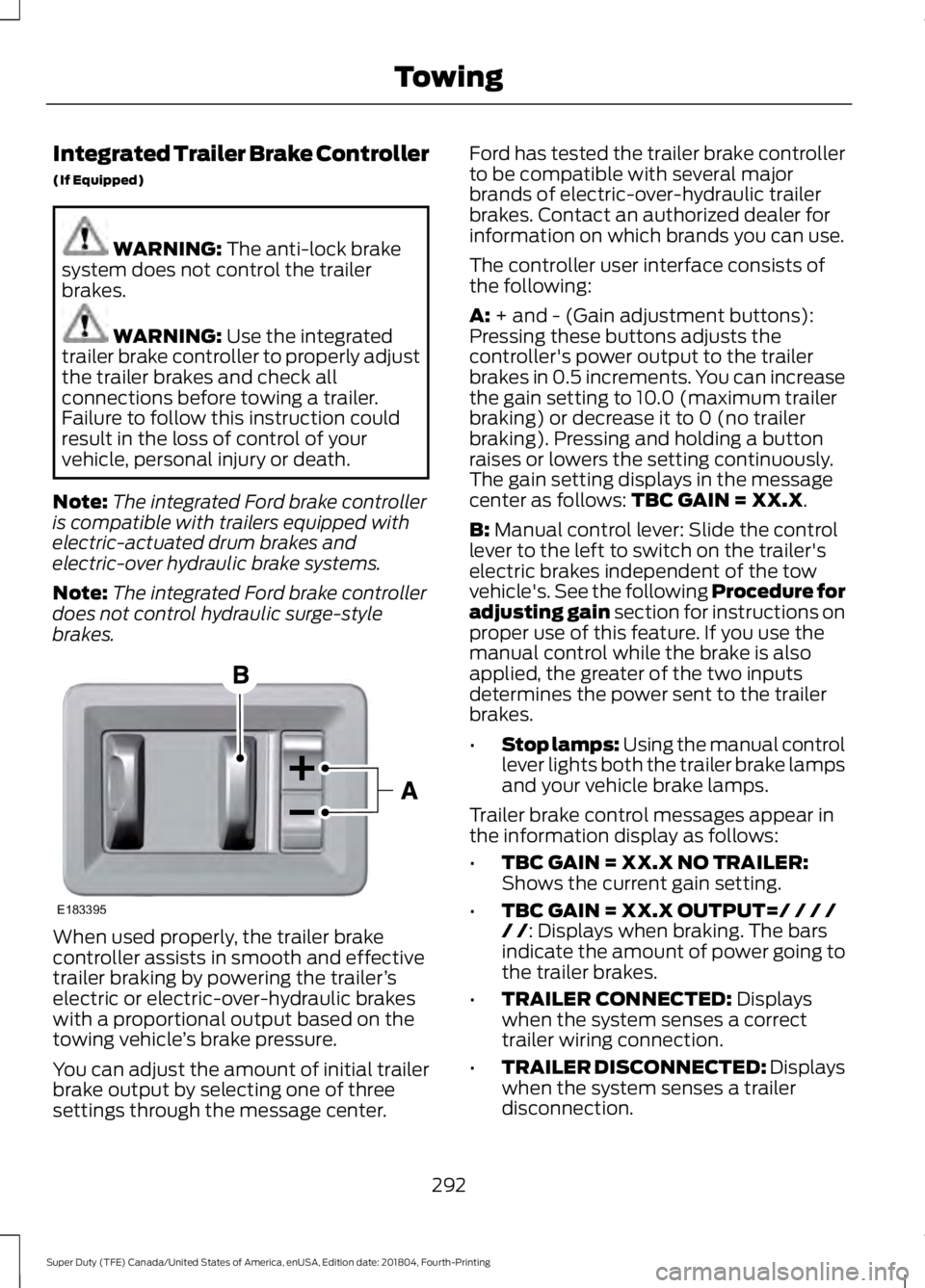
The controller user interface consists of
the following:
A: + and - (Gain adjustment buttons):
Pressing these buttons adjusts the
controller's power output to the trailer
brakes in 0.5 increments. You can increase
the gain setting to 10.0 (maximum trailer
braking) or decrease it to 0 (no trailer
braking). Pressing and holding a button
raises or lowers the setting continuously.
The gain setting displays in the message
center as follows:
TBC GAIN = XX.X.
B:
Manual control lever: Slide the control
lever to the left to switch on the trailer's
electric brakes independent of the tow
vehicle's. See the following Procedure for
adjusting gain section for instructions on
proper use of this feature. If you use the
manual control while the brake is also
applied, the greater of the two inputs
determines the power sent to the trailer
brakes.
• Stop lamps: Using the manual control
lever lights both the trailer brake lamps
and your vehicle brake lamps.
Trailer brake control messages appear in
the information display as follows:
• TBC GAIN = XX.X NO TRAILER:
Shows the current gain setting.
• TBC GAIN = XX.X OUTPUT=/ / / /
/ /
: Displays when braking. The bars
indicate the amount of power going to
the trailer brakes.
• TRAILER CONNECTED:
Displays
when the system senses a correct
trailer wiring connection.
• TRAILER DISCONNECTED: Displays
when the system senses a trailer
disconnection.
292
Super Duty (TFE) Canada/United States of America, enUSA, Edition date: 201804, Fourth-Printing TowingE183395