2019 FORD F-150 lights
[x] Cancel search: lightsPage 273 of 644

PRE-COLLISION ASSIST (IF
EQUIPPED) WARNING:
You are responsible
for controlling your vehicle at all times.
The system is designed to be an aid and
does not relieve you of your responsibility
to drive with due care and attention.
Failure to follow this instruction could
result in the loss of control of your
vehicle, personal injury or death. WARNING:
The system does not
detect vehicles that are driving in a
different direction, cyclists or animals.
Failure to take care may result in the loss
of control of your vehicle, serious
personal injury or death. WARNING:
The system does not
operate during hard acceleration or
steering. Failure to take care may lead
to a crash or personal injury. WARNING:
The system may fail
or operate with reduced function during
cold and severe weather conditions.
Snow, ice, rain, spray and fog can
adversely affect the system. Keep the
front camera and radar free of snow and
ice. Failure to take care may result in the
loss of control of your vehicle, serious
personal injury or death. WARNING: In situations where the
vehicle camera has limited detection
capability, this may reduce system
performance. These situations include
but are not limited to direct or low
sunlight, vehicles at night without tail
lights, unconventional vehicle types,
pedestrians with complex backgrounds, partly obscured pedestrians, or
pedestrians that the system cannot
distinguish from a group. Failure to take
care may result in the loss of control of
your vehicle, serious personal injury or
death.
WARNING:
The system cannot
help prevent all crashes. Do not rely on
this system to replace driver judgment
and the need to maintain a safe distance
and speed.
Using the Pre-Collision Assist
System
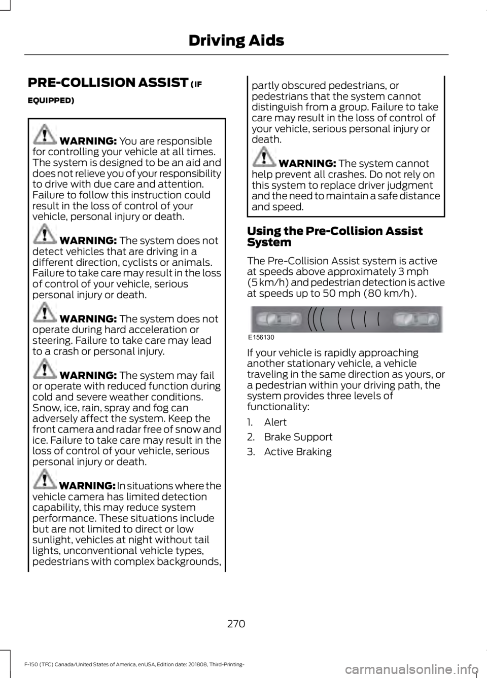
The Pre-Collision Assist system is active
at speeds above approximately
3 mph
(5 km/h) and pedestrian detection is active
at speeds up to
50 mph (80 km/h). If your vehicle is rapidly approaching
another stationary vehicle, a vehicle
traveling in the same direction as yours, or
a pedestrian within your driving path, the
system provides three levels of
functionality:
1. Alert
2. Brake Support
3. Active Braking
270
F-150 (TFC) Canada/United States of America, enUSA, Edition date: 201808, Third-Printing- Driving AidsE156130
Page 313 of 644

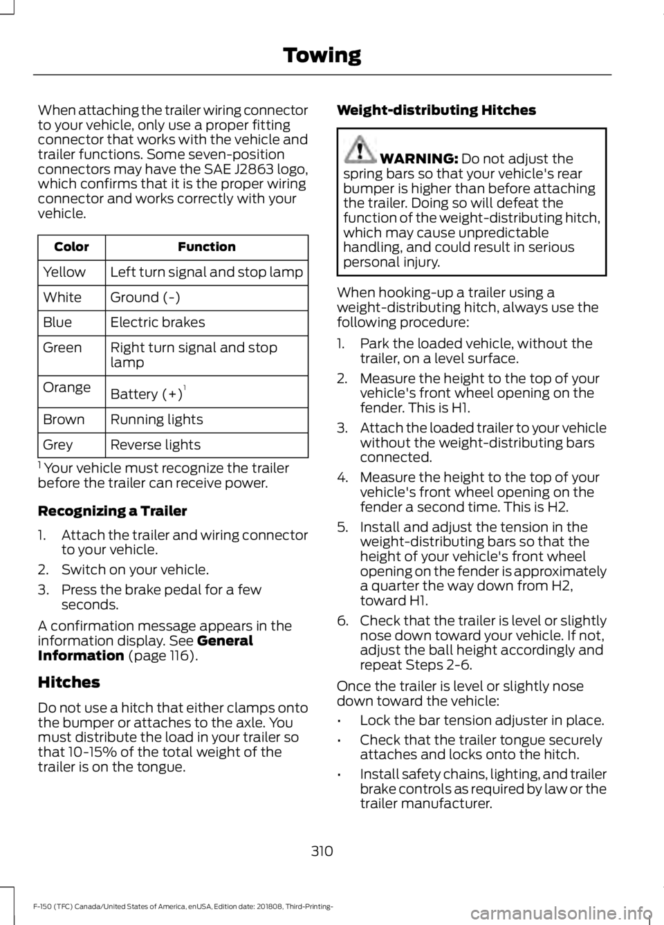
When attaching the trailer wiring connector
to your vehicle, only use a proper fitting
connector that works with the vehicle and
trailer functions. Some seven-position
connectors may have the SAE J2863 logo,
which confirms that it is the proper wiring
connector and works correctly with your
vehicle.
Function
Color
Left turn signal and stop lamp
Yellow
Ground (-)
White
Electric brakes
Blue
Right turn signal and stop
lamp
Green
Battery (+) 1
Orange
Running lights
Brown
Reverse lights
Grey
1 Your vehicle must recognize the trailer
before the trailer can receive power.
Recognizing a Trailer
1. Attach the trailer and wiring connector
to your vehicle.
2. Switch on your vehicle.
3. Press the brake pedal for a few seconds.
A confirmation message appears in the
information display. See General
Information (page 116).
Hitches
Do not use a hitch that either clamps onto
the bumper or attaches to the axle. You
must distribute the load in your trailer so
that 10-15% of the total weight of the
trailer is on the tongue. Weight-distributing Hitches WARNING:
Do not adjust the
spring bars so that your vehicle's rear
bumper is higher than before attaching
the trailer. Doing so will defeat the
function of the weight-distributing hitch,
which may cause unpredictable
handling, and could result in serious
personal injury.
When hooking-up a trailer using a
weight-distributing hitch, always use the
following procedure:
1. Park the loaded vehicle, without the trailer, on a level surface.
2. Measure the height to the top of your vehicle's front wheel opening on the
fender. This is H1.
3. Attach the loaded trailer to your vehicle
without the weight-distributing bars
connected.
4. Measure the height to the top of your vehicle's front wheel opening on the
fender a second time. This is H2.
5. Install and adjust the tension in the weight-distributing bars so that the
height of your vehicle's front wheel
opening on the fender is approximately
a quarter the way down from H2,
toward H1.
6. Check that the trailer is level or slightly
nose down toward your vehicle. If not,
adjust the ball height accordingly and
repeat Steps 2-6.
Once the trailer is level or slightly nose
down toward the vehicle:
• Lock the bar tension adjuster in place.
• Check that the trailer tongue securely
attaches and locks onto the hitch.
• Install safety chains, lighting, and trailer
brake controls as required by law or the
trailer manufacturer.
310
F-150 (TFC) Canada/United States of America, enUSA, Edition date: 201808, Third-Printing- Towing
Page 317 of 644

Points to Remember
Note:
Do not attempt removal of the trailer
brake controller without consulting the
Workshop Manual. Damage to the unit may
result.
• Adjust gain setting before using the
trailer brake controller for the first time.
• Adjust gain setting, using the procedure
above, whenever road, weather and
trailer or vehicle loading conditions
change from when the gain was initially
set.
• Only use the manual control lever for
proper adjustment of the gain during
trailer setup. Misuse, such as
application during trailer sway, could
cause instability of trailer or tow
vehicle.
• Avoid towing in adverse weather
conditions. The trailer brake controller
does not provide anti-lock control of
the trailer wheels. Trailer wheels can
lock up on slippery surfaces, resulting
in reduced stability of trailer and tow
vehicle.
• The trailer brake controller is equipped
with a feature that reduces output at
vehicle speeds below 11 mph (18 km/h)
so trailer and vehicle braking is not jerky
or harsh. This feature is only available
when applying the brakes using your
vehicle's brake pedal, not the
controller.
• The controller interacts with the brake
control system and powertrain control
system of your vehicle to provide the
best performance on different road
conditions.
• Your vehicle's brake system and the
trailer brake system work
independently of each other. Changing
the gain setting on the controller does
not affect the operation of your
vehicle's brakes whether you attach a
trailer or not. •
When you switch the engine off, the
controller output is disabled and the
display and module shut down. The
controller module and display turn on
when you switch the ignition on.
• The trailer brake controller is only a
factory-installed or dealer-installed
item. Ford is not responsible for
warranty or performance of the
controller due to misuse or customer
installation.
Trailer Lamps WARNING: Never connect any
trailer lamp wiring to the vehicle's tail
lamp wiring; this may damage the
electrical system resulting in fire. Contact
your authorized dealer as soon as
possible for assistance in proper trailer
tow wiring installation. Additional
electrical equipment may be required.
Trailer lamps are required on most towed
vehicles. Make sure all running lights, brake
lights, turn signals and hazard lights are
working.
Using a Step Bumper
(If Equipped)
The rear bumper is equipped with an
integral hitch and only requires a ball with
a one-inch (25.4 millimeter) shank
diameter. The bumper has a
5,000 lb
(2,268 kg) trailer weight and a 500 lb
(227 kg) tongue weight capacity.
If it is necessary to relocate the hitch ball
position, you must install a frame-mounted
trailer hitch.
314
F-150 (TFC) Canada/United States of America, enUSA, Edition date: 201808, Third-Printing- Towing
Page 325 of 644

When driving through standing water, drive
very slowly and do not stop your vehicle.
Your brake performance and traction may
be limited. After driving through water and
as soon as it is safe to do so:
•
Lightly press the brake pedal to dry the
brakes and to check that they work.
• Check that the horn works.
• Check that the exterior lights work.
• Turn the steering wheel to check that
the steering power assist works.
FLOOR MATS WARNING: Use a floor mat
designed to fit the footwell of your
vehicle that does not obstruct the pedal
area. Failure to follow this instruction
could result in the loss of control of your
vehicle, personal injury or death. WARNING:
Pedals that cannot
move freely can cause loss of vehicle
control and increase the risk of serious
personal injury. WARNING:
Secure the floor mat
to both retention devices so that it
cannot slip out of position and interfere
with the pedals. Failure to follow this
instruction could result in the loss of
control of your vehicle, personal injury or
death. WARNING:
Do not place
additional floor mats or any other
covering on top of the original floor mats.
This could result in the floor mat
interfering with the operation of the
pedals. Failure to follow this instruction
could result in the loss of control of your
vehicle, personal injury or death. WARNING: Always make sure that
objects cannot fall into the driver foot
well while your vehicle is moving. Objects
that are loose can become trapped
under the pedals causing a loss of
vehicle control. To install the floor mats, position the floor
mat eyelet over the retention post and
press down to lock in position.
To remove the floor mat, reverse the
installation procedure.
Note:
Regularly check the floor mats to
make sure they are secure.
322
F-150 (TFC) Canada/United States of America, enUSA, Edition date: 201808, Third-Printing- Driving HintsE176913 E142666
Page 327 of 644

Note:
The electrical system is designed to
support the addition of a residential
snowplow (up to 60 Amps continuous) and
snowplow lights (up to 20 Amps
continuous) using snowplow mode. The
system is not designed to support snowplow
usage with additional electrical aftermarket
accessories.
Operating the Vehicle with the
Snowplow Attached
Note: Drive the vehicle at least 500 mi
(800 km) before using your vehicle for snow
removal.
We recommend vehicle speed does not
exceed
45 mph (72 km/h) when
snowplowing.
The attached snowplow blade restricts
airflow to the radiator, and may cause the
engine to run at a higher temperature.
Attention to engine temperature is
especially important when outside
temperatures are above freezing. Angle
the blade to maximize airflow to the
radiator and monitor engine temperature
to determine whether a left or right angle
provides the best performance.
Follow the severe duty schedule in your
Scheduled Maintenance information for
engine oil and transmission fluid change
intervals.
Snowplowing with your Airbag
Equipped Vehicle WARNING:
Do not attempt to
service, repair, or modify the airbag
supplemental restraint systems or its
fuses on a vehicle containing air bags as
you could be seriously injured or killed.
Contact your authorized dealer as soon
as possible. WARNING:
All occupants of your
vehicle, including the driver, should
always properly wear their seatbelts,
even when an airbag supplemental
restraint system is provided. Failure to
properly wear your seatbelt could
seriously increase the risk of injury or
death. WARNING:
Modifying or adding
equipment to the front end of your
vehicle (including hood, bumper system,
frame, front end body structure, tow
hooks and hood pins) may affect the
performance of the airbag system,
increasing the risk of injury. Do not
modify or add equipment to the front
end of your vehicle.
Note: Please refer to the Body Builders
Layout Book for instructions about the
appropriate installation of additional
equipment.
Your vehicle is equipped with a driver and
passenger airbag supplemental restraint
system. The supplemental restraint system
activates in certain frontal and offset
frontal collisions when the vehicle sustains
sufficient longitudinal deceleration.
Careless or high speed driving while
snowplowing, which results in significant
vehicle decelerations, can deploy the
airbag. Such driving also increases the risk
of accidents.
Never remove or defeat the tripping
mechanisms designed into the snow
removal equipment by its manufacturer.
Doing so may cause damage to the vehicle
and the snow removal equipment as well
as possible airbag deployment.
324
F-150 (TFC) Canada/United States of America, enUSA, Edition date: 201808, Third-Printing- Driving Hints
Page 522 of 644

3D city models are complete 3D models
of entire city areas including navigable
roads, parks, rivers and rendered buildings.
3D landmarks and city models appear in
3D map mode only. Coverage of these
varies and improves with updated map
releases.
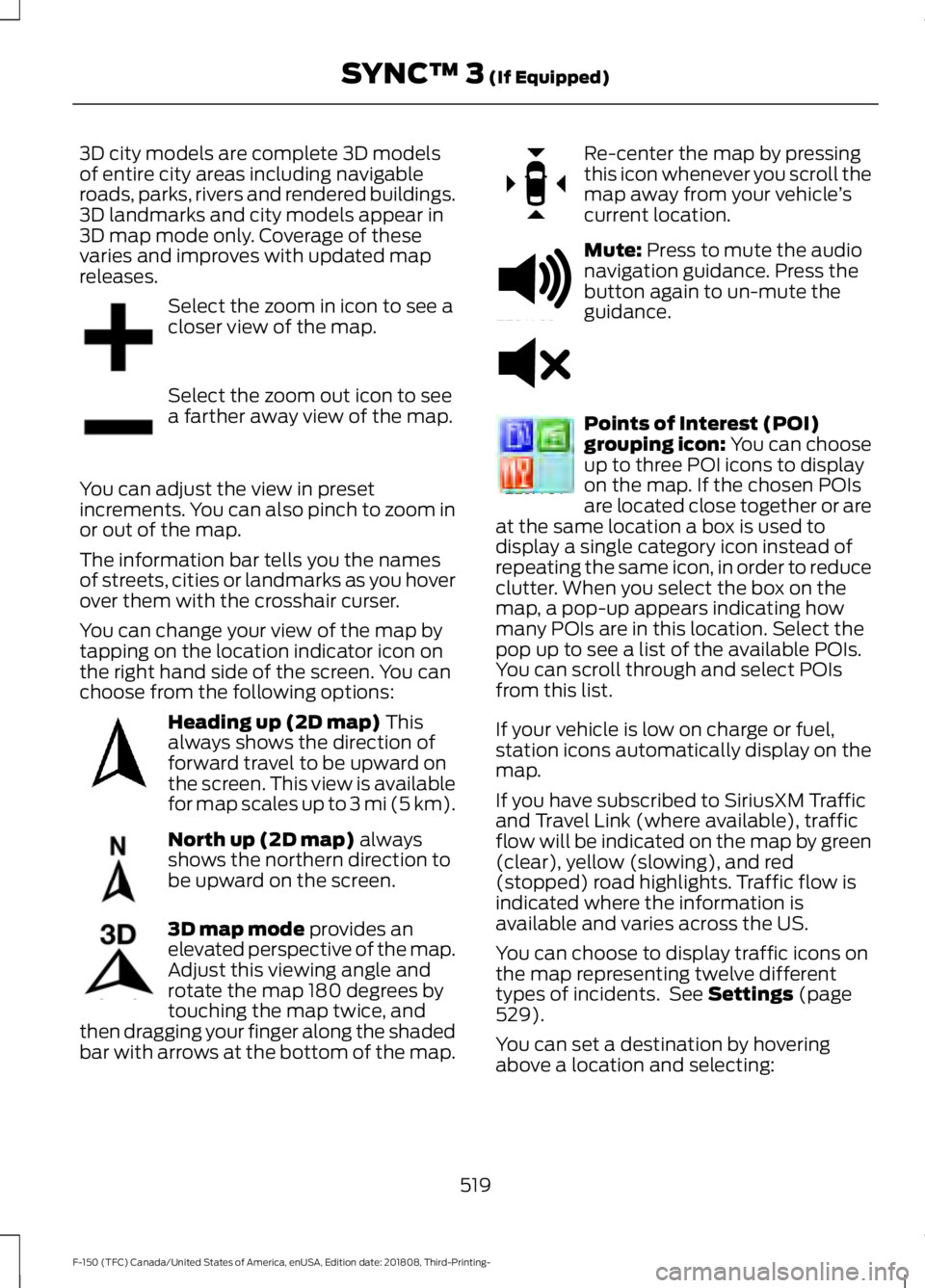
Select the zoom in icon to see a
closer view of the map.
Select the zoom out icon to see
a farther away view of the map.
You can adjust the view in preset
increments. You can also pinch to zoom in
or out of the map.
The information bar tells you the names
of streets, cities or landmarks as you hover
over them with the crosshair curser.
You can change your view of the map by
tapping on the location indicator icon on
the right hand side of the screen. You can
choose from the following options: Heading up (2D map) This
always shows the direction of
forward travel to be upward on
the screen. This view is available
for map scales up to
3 mi (5 km). North up (2D map)
always
shows the northern direction to
be upward on the screen. 3D map mode
provides an
elevated perspective of the map.
Adjust this viewing angle and
rotate the map 180 degrees by
touching the map twice, and
then dragging your finger along the shaded
bar with arrows at the bottom of the map. Re-center the map by pressing
this icon whenever you scroll the
map away from your vehicle
’s
current location. Mute:
Press to mute the audio
navigation guidance. Press the
button again to un-mute the
guidance. Points of Interest (POI)
grouping icon: You can choose
up to three POI icons to display
on the map. If the chosen POIs
are located close together or are
at the same location a box is used to
display a single category icon instead of
repeating the same icon, in order to reduce
clutter. When you select the box on the
map, a pop-up appears indicating how
many POIs are in this location. Select the
pop up to see a list of the available POIs.
You can scroll through and select POIs
from this list.
If your vehicle is low on charge or fuel,
station icons automatically display on the
map.
If you have subscribed to SiriusXM Traffic
and Travel Link (where available), traffic
flow will be indicated on the map by green
(clear), yellow (slowing), and red
(stopped) road highlights. Traffic flow is
indicated where the information is
available and varies across the US.
You can choose to display traffic icons on
the map representing twelve different
types of incidents. See
Settings (page
529).
You can set a destination by hovering
above a location and selecting:
519
F-150 (TFC) Canada/United States of America, enUSA, Edition date: 201808, Third-Printing- SYNC™ 3
(If Equipped)E207752 E207753 E207750 E207749 E207748 E207751 E251780 E251779 E207754
Page 545 of 644

Camera Settings
To make adjustments using the touchscreen, select:
Action and Description
Message
Camera Settings
Then select from the following: When the reverse sensing system detects an object, it displays red,
yellow and green highlights at the top of the image.
Enhanced Park
Aids
You can enable or disable this option using the slider.
Rear Camera
Delay
Onboard Modem Serial Number (ESN)
Selecting this button on the settings menu
shows you the ESN number for your
system. You need this number for certain
registrations such as Satellite Radio.
Display
To make adjustments using the touchscreen, select: Action and Description
Menu Item
The screen goes black and does not display anything. To switch the
screen back on, simply tap the screen.
Display Off
Make the screen display brighter or dimmer.
Brightness
Enable this option to have your screen display minimal content.
Pressing anywhere on the screen, using the reverse camera, or touching
an interactive icon returns the screen to normal content.
Calm Screen
Allows you to select a screen background color.
Background
You can select:
Mode
The screen automatically switches between day and
night modes based on the outside light level.
Auto
542
F-150 (TFC) Canada/United States of America, enUSA, Edition date: 201808, Third-Printing- SYNC™ 3 (If Equipped)
Page 567 of 644

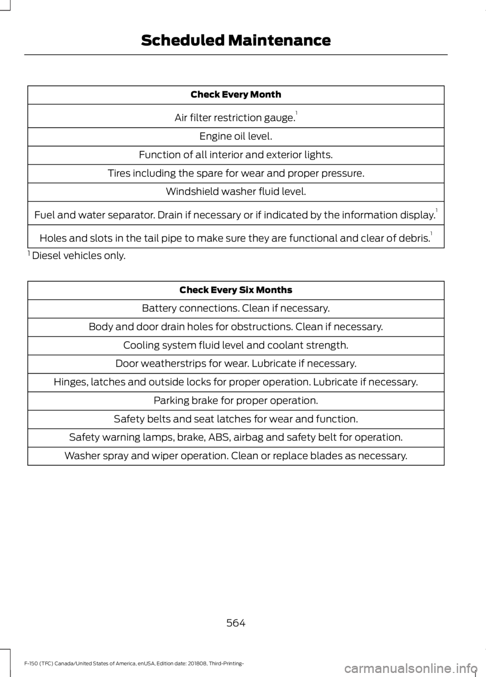
Check Every Month
Air filter restriction gauge. 1
Engine oil level.
Function of all interior and exterior lights.
Tires including the spare for wear and proper pressure. Windshield washer fluid level.
Fuel and water separator. Drain if necessary or if indicated by the information display. 1
Holes and slots in the tail pipe to make sure they are functional and clear of debris. 1
1 Diesel vehicles only. Check Every Six Months
Battery connections. Clean if necessary.
Body and door drain holes for obstructions. Clean if necessary. Cooling system fluid level and coolant strength.
Door weatherstrips for wear. Lubricate if necessary.
Hinges, latches and outside locks for proper operation. Lubricate if necessary. Parking brake for proper operation.
Safety belts and seat latches for wear and function.
Safety warning lamps, brake, ABS, airbag and safety belt for operation.
Washer spray and wiper operation. Clean or replace blades as necessary.
564
F-150 (TFC) Canada/United States of America, enUSA, Edition date: 201808, Third-Printing- Scheduled Maintenance